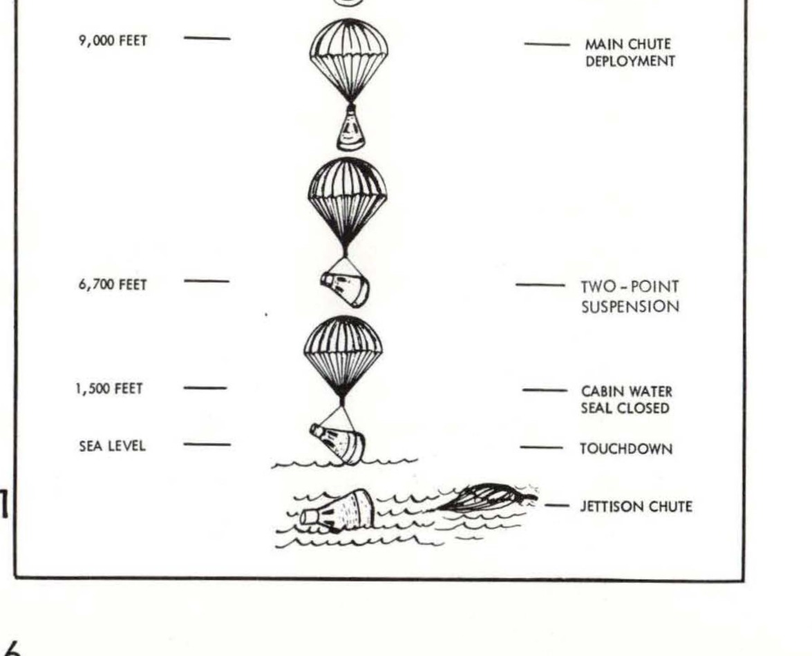
GEMINI PARACHUTE LANDING SEQUENCE showing descent stages from 30,000 feet to touchdown with labeled parachute deployments
Related photos

NASA logo

Apollo Program logo

NASA logo

Manned Spacecraft Center logo
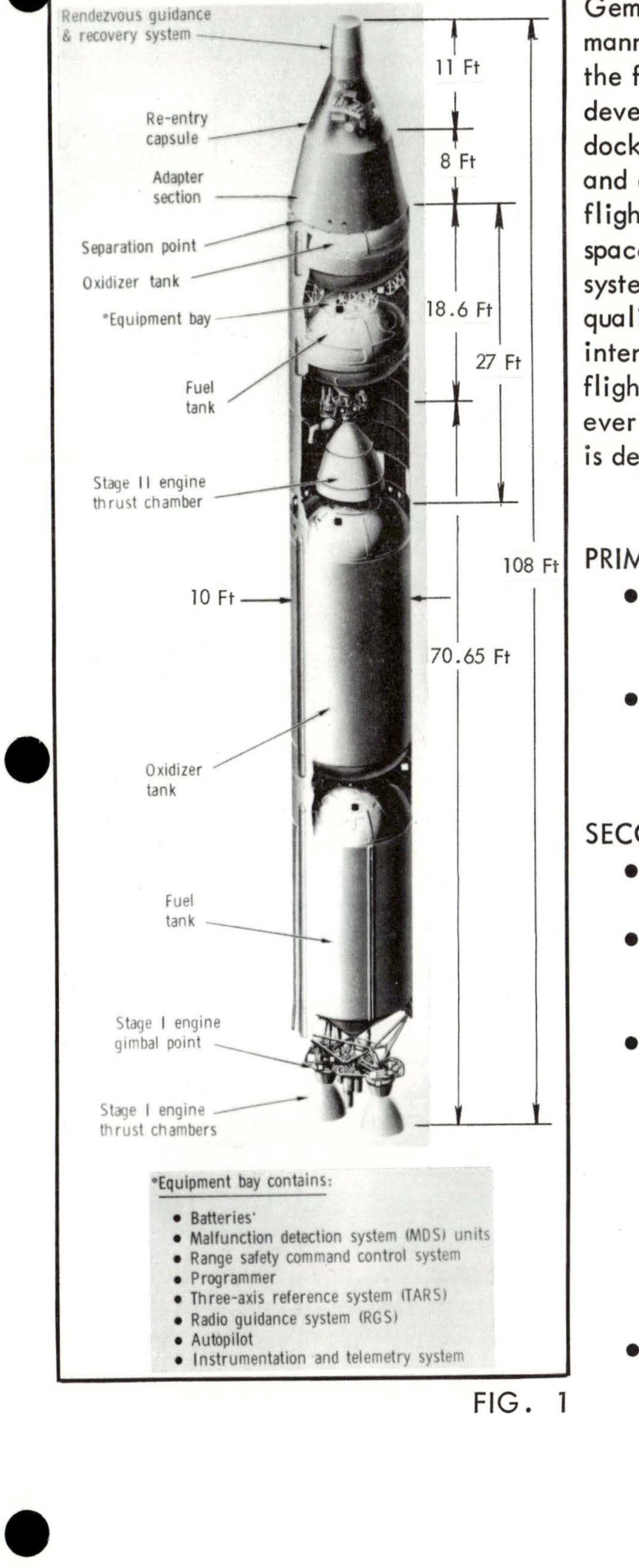
FIG. 1 - Labeled diagram of Gemini spacecraft showing components including rendezvous guidance & recovery system, re-entry capsule, adapter section, separation point, oxidizer tank, equipment bay, fuel tank, Stage II engine thrust chamber, Stage I engine gimbal point, and Stage I engine thrust chambers. Equipment bay contains: Batteries, Malfunction detection system (MDS) units, Range safety command control set, Programmer, Three-axis reference system (TARS), Reaction control system (RCS), Autopilot, Instrumentation and telemetry system.
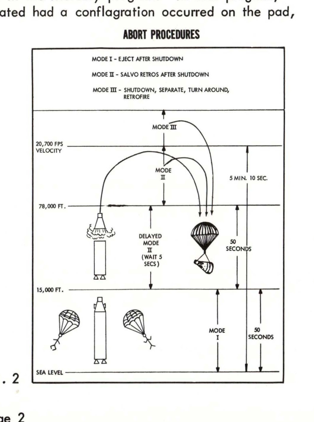
Abort procedures diagram showing three modes with altitude and time parameters, including velocity markers at 29,700 FPS and 78,000 FT, with delayed mode and retrofire sequences
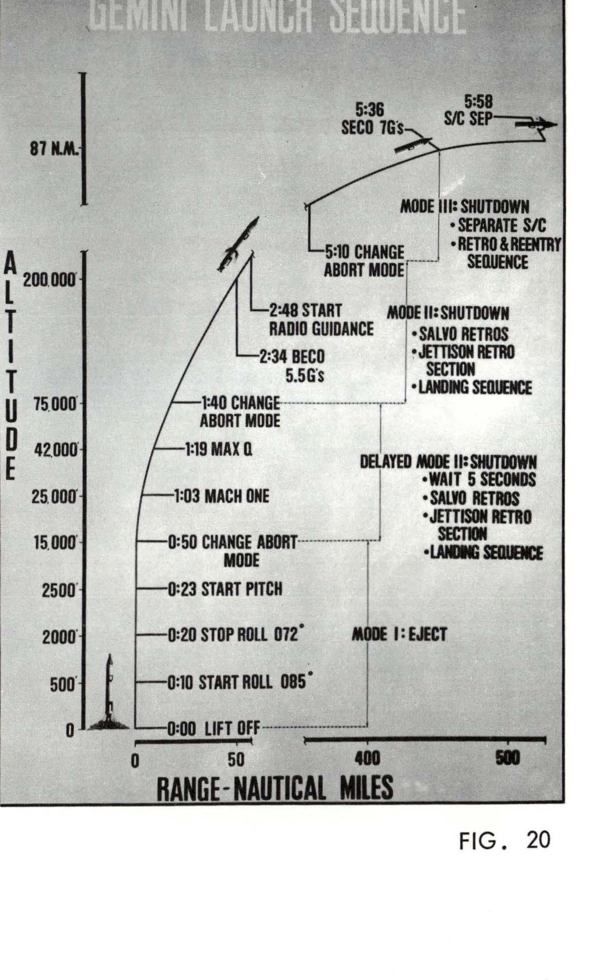
GEMINI LAUNCH SEQUENCE - Figure 20 showing altitude vs range trajectory with mission events
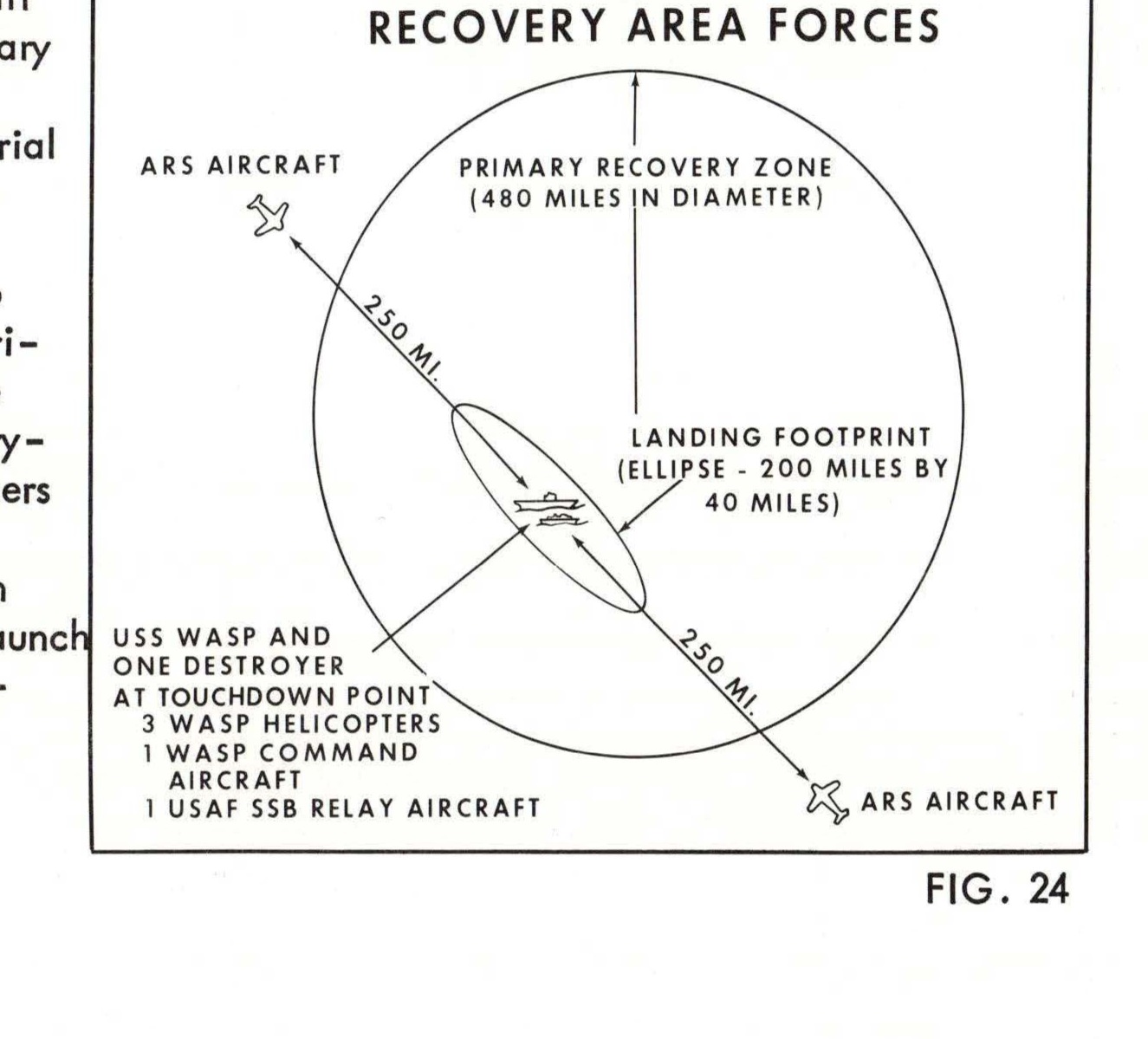
Recovery Area Forces diagram showing primary recovery zone, landing footprint, and deployment of USS WASP, destroyer, helicopters, and aircraft