
Photo gallery
Images extracted from documents: photographs, sketches, maps and diagrams.
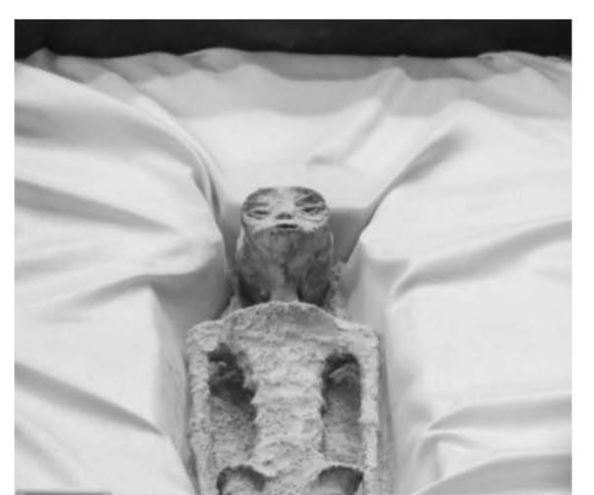
(U) Figure 1: Mexican journalist Jaime Maussan presented the alleged remains of non-human beings to Congress. (Photo credit: Reuters)
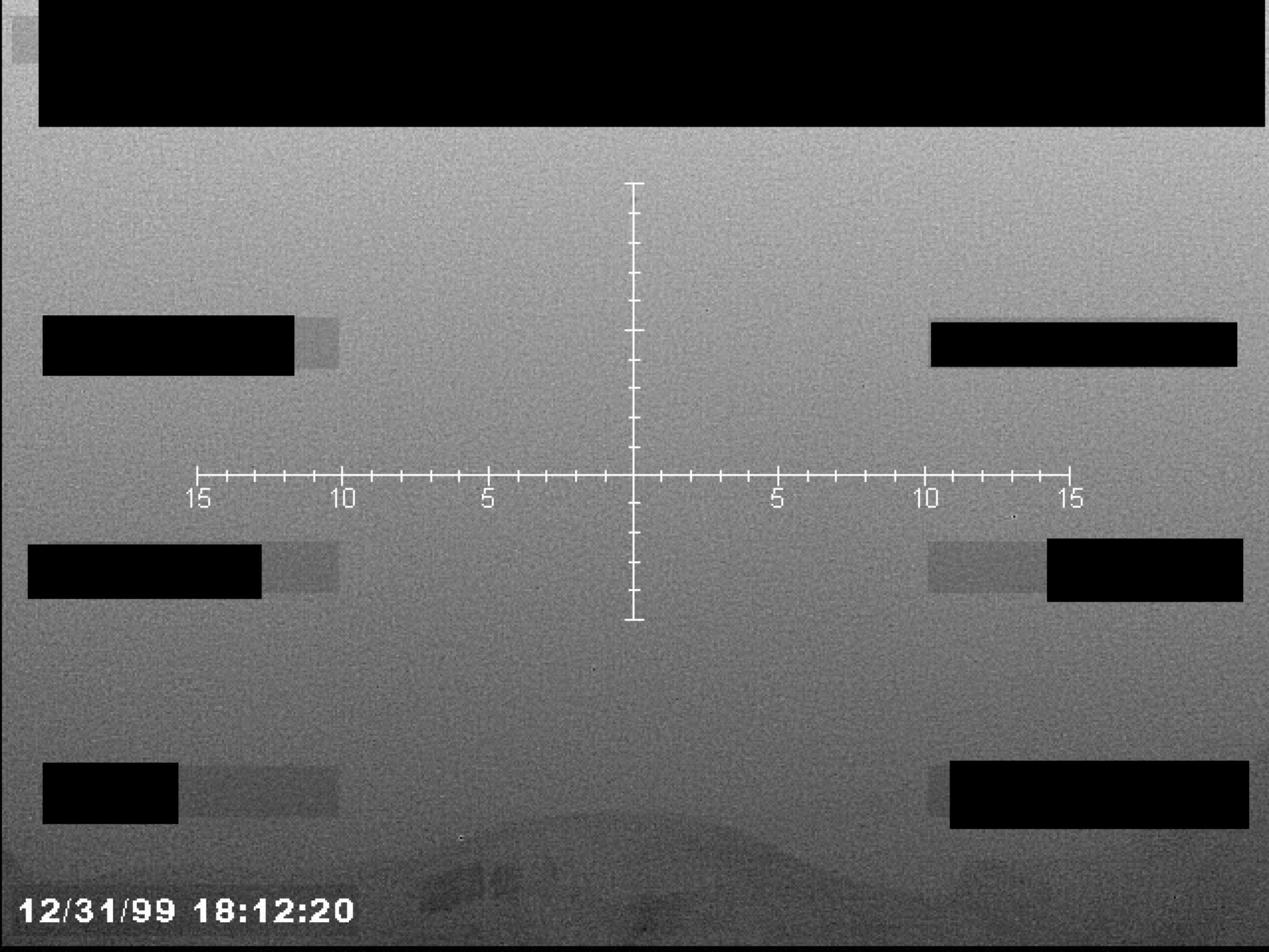
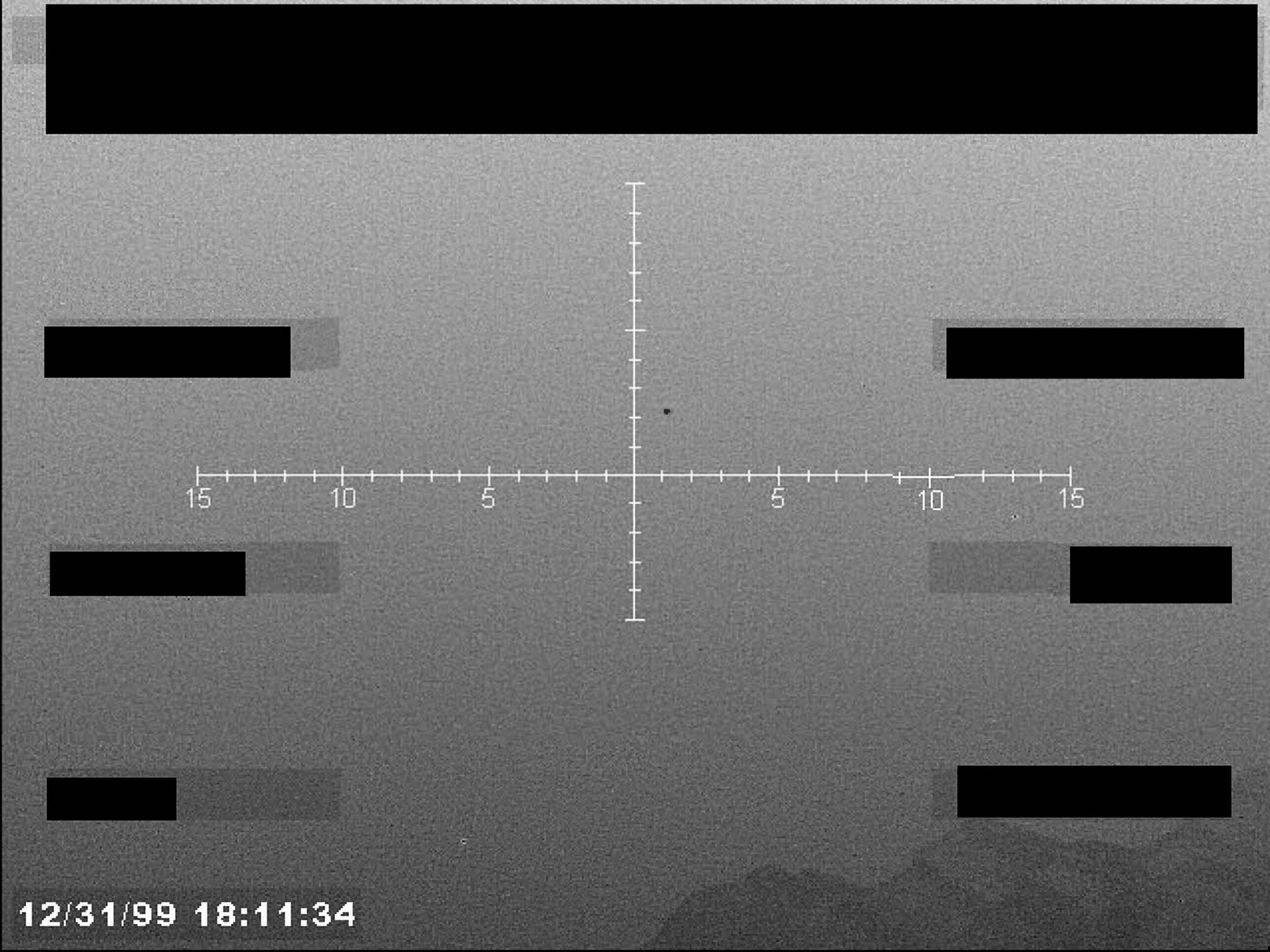
A sensor display, possibly infrared, showing a crosshair reticle with a numerical scale and a timestamp at the bottom left.
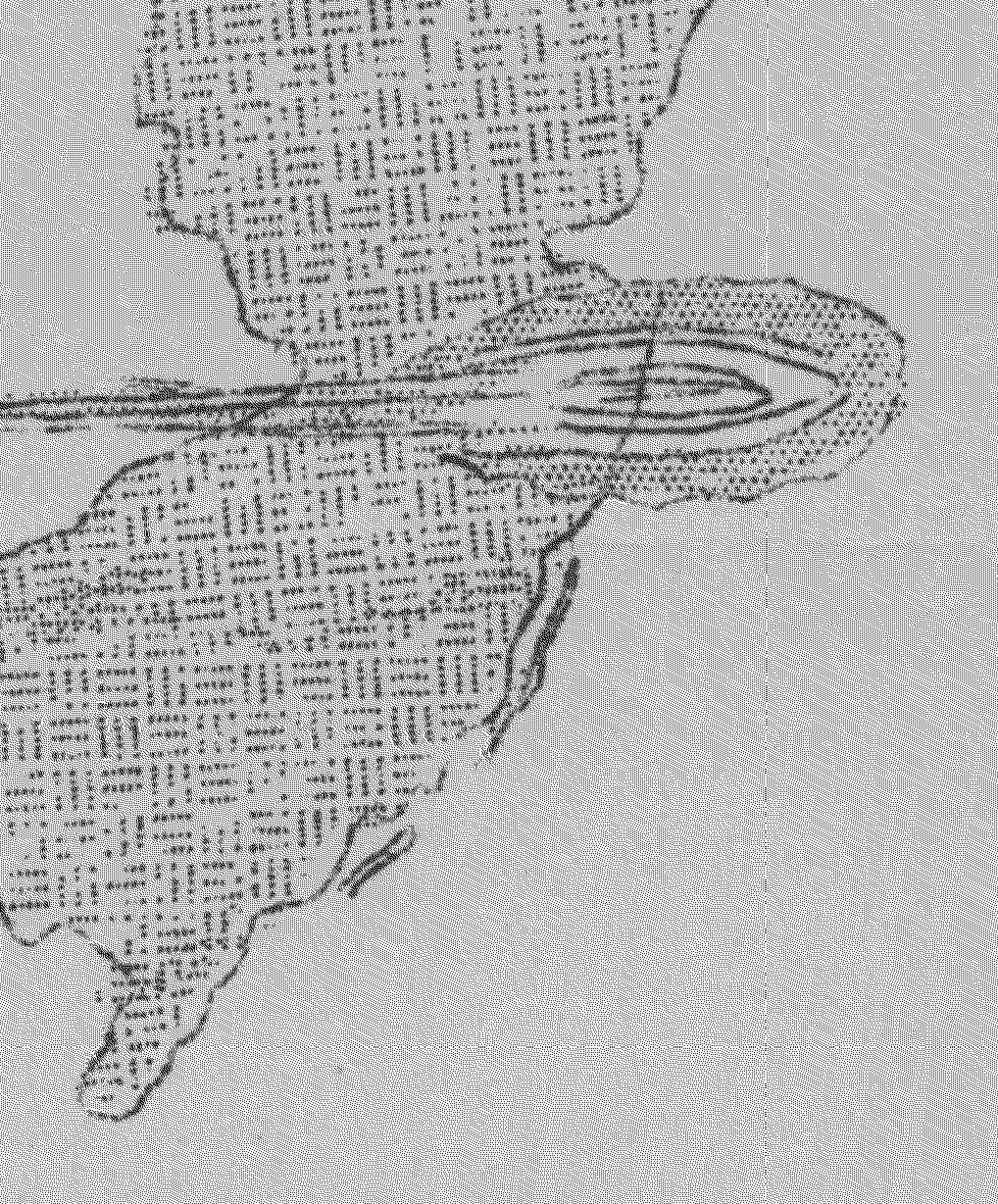
A sketch of a flying saucer over the state of New Jersey.

Seal of the Westwood Police Department.
Logo of the Department of Police, Westwood, NJ.
Seal of the Police of N.J.
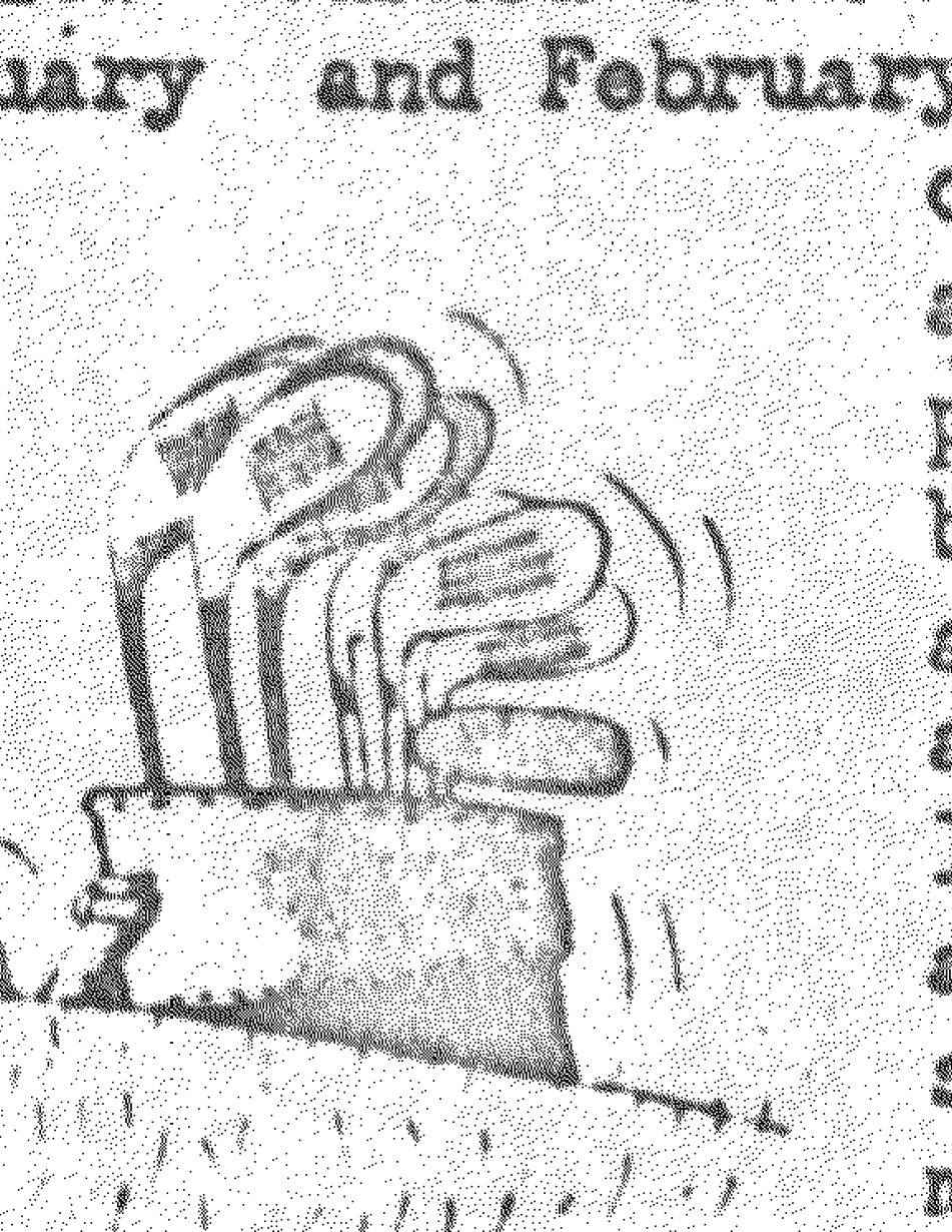
A cartoon sketch of a person being abducted by a flying saucer.

Seal of the Department of Justice, Federal Bureau of Investigation.
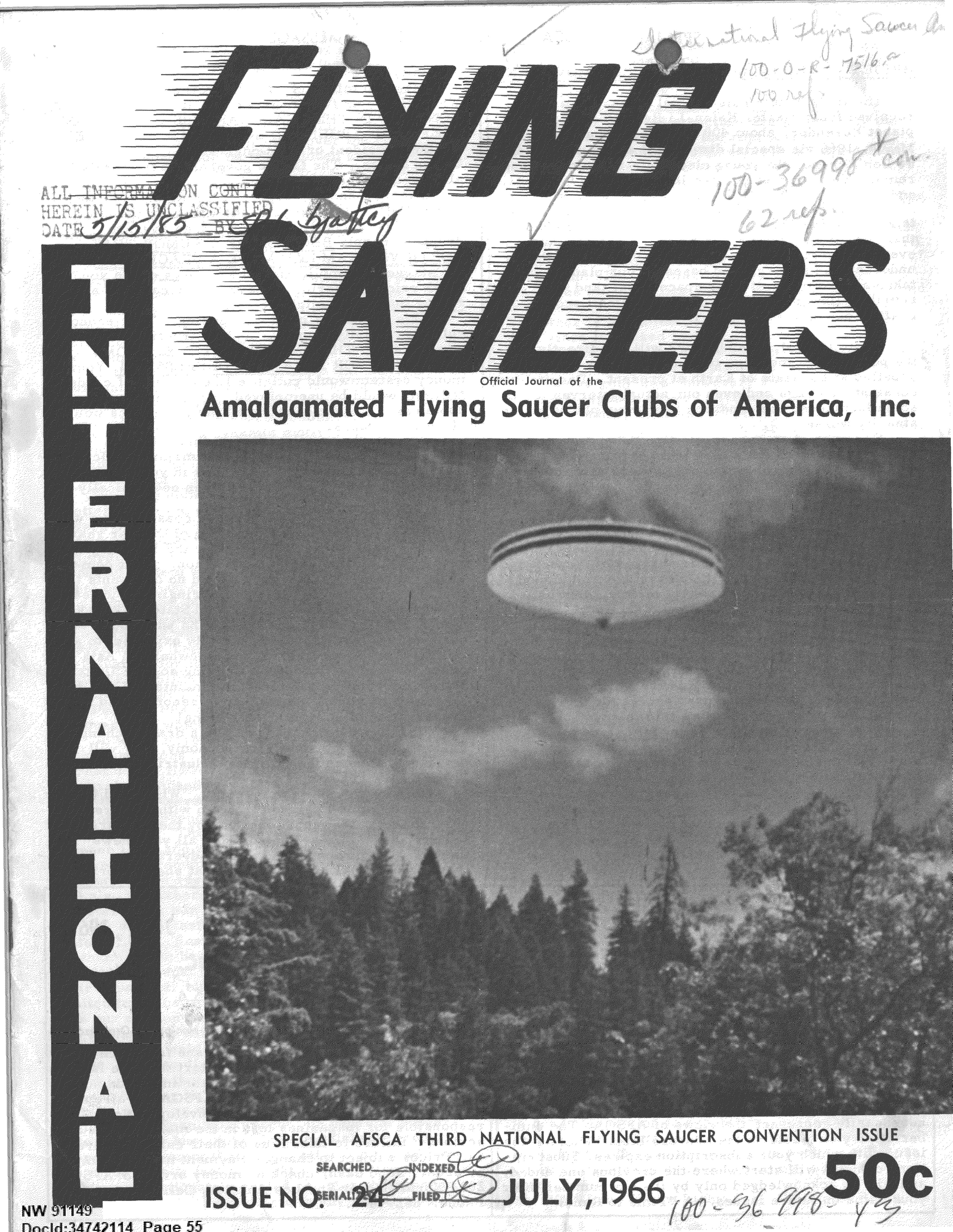
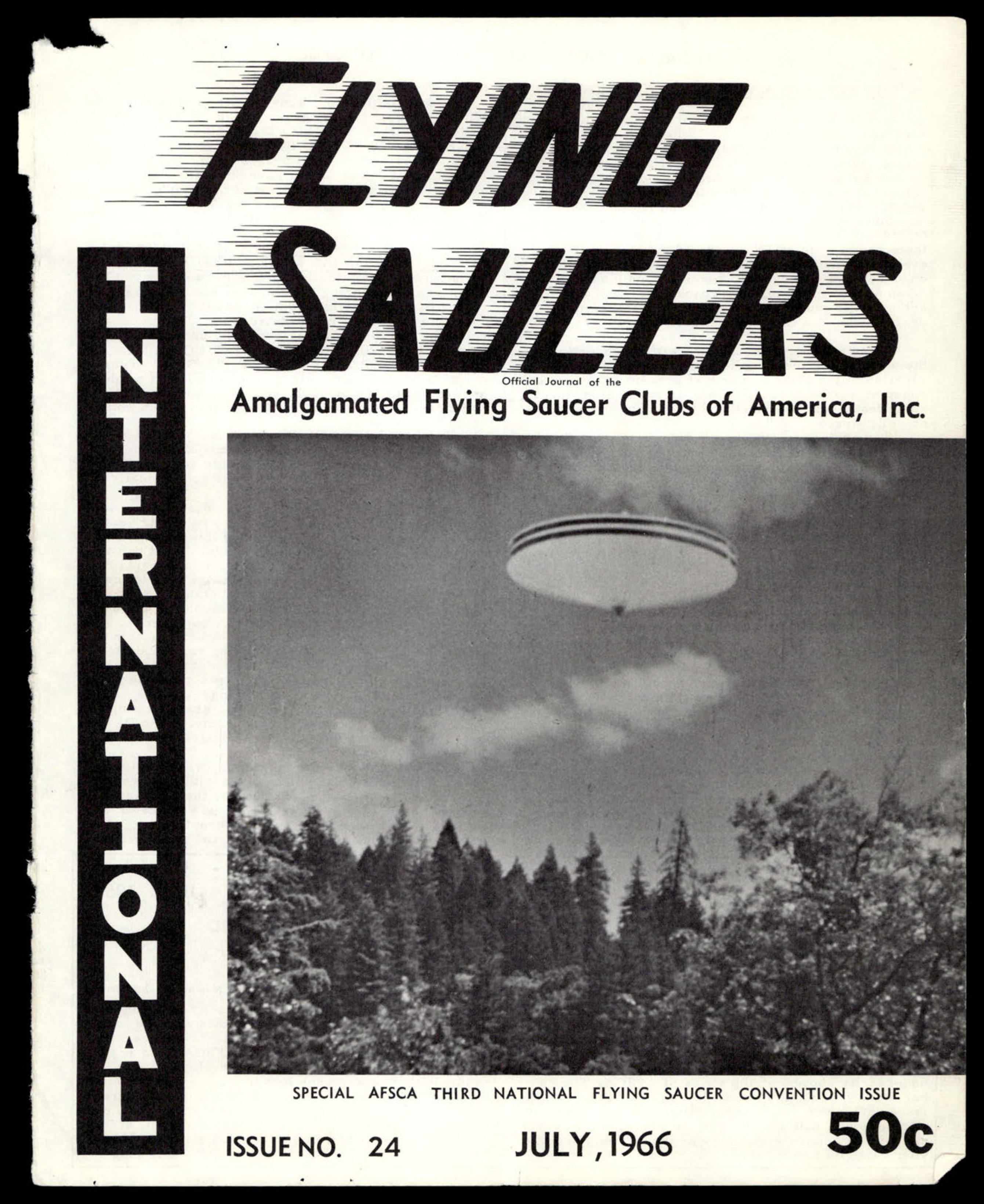
A photograph of a flying saucer hovering over a forested area.
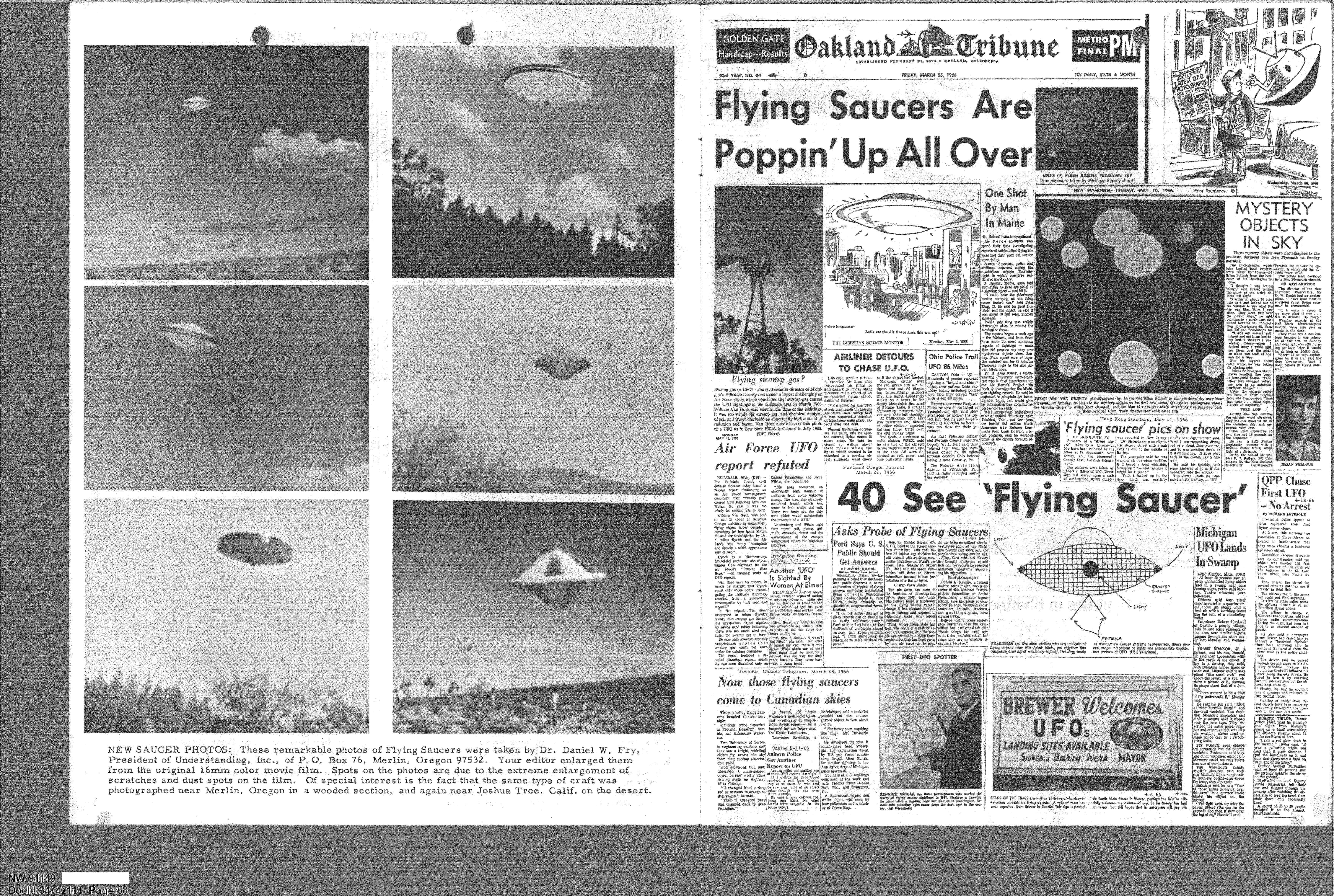
A collage of newspaper clippings and photographs related to UFO sightings from various sources, including the Oakland Tribune and others. The page is dominated by images of alleged UFOs and headlines like 'Flying Saucers Are Poppin' Up All Over'.
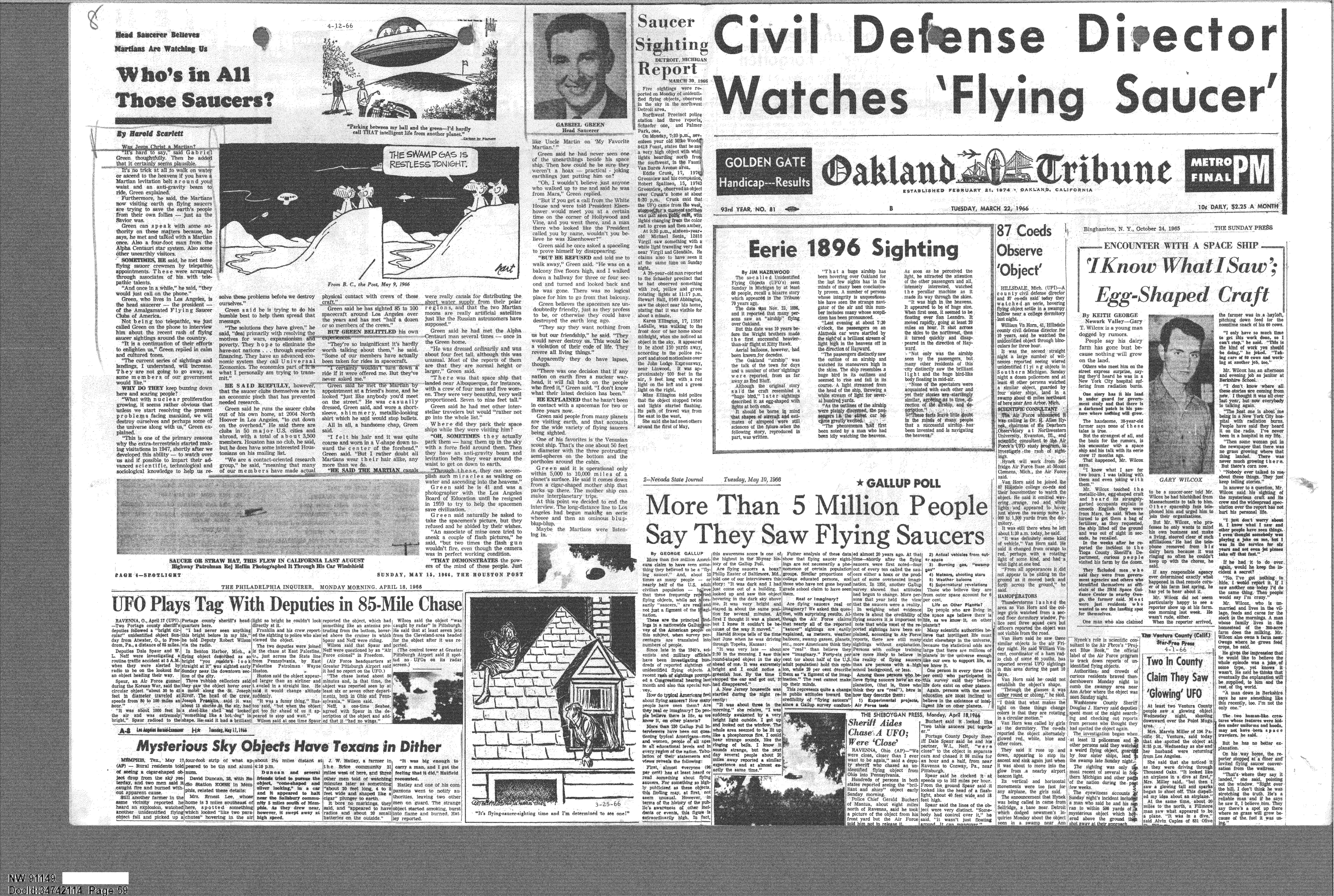
A collage of newspaper clippings about UFO sightings. Headlines include 'Civil Defense Director Watches 'Flying Saucer'', 'Eerie 1896 Sighting', and 'More Than 5 Million People Say They Saw Flying Saucers'. The page is from various newspapers, including the Oakland Tribune.
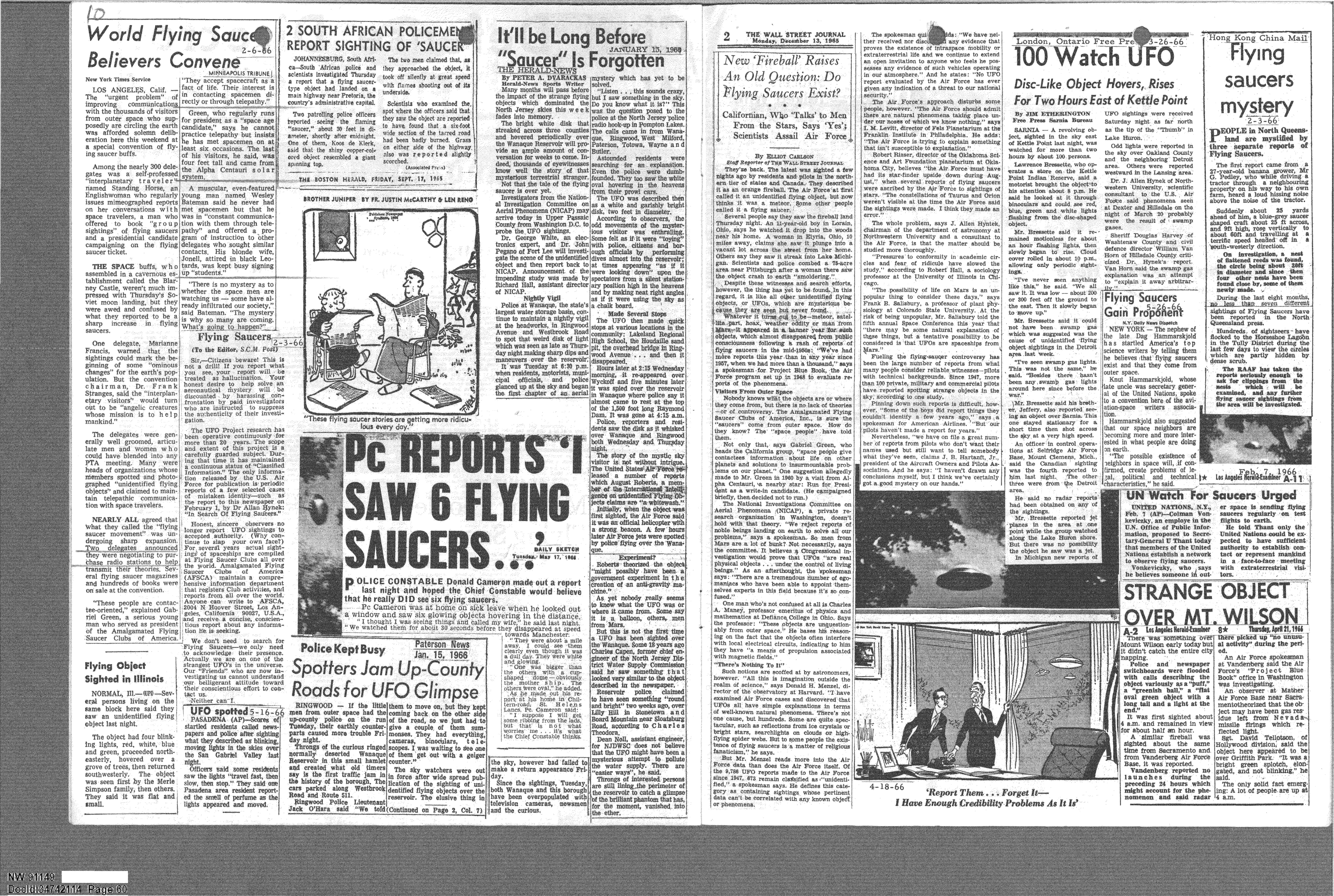
A collage of newspaper clippings about UFO sightings from sources like The Wall Street Journal and Hong Kong China Mail. Headlines include '2 SOUTH AFRICAN POLICEMEN REPORT SIGHTING OF 'SAUCER'', 'PC REPORTS I SAW 6 FLYING SAUCERS', and '100 WATCH UFO'.
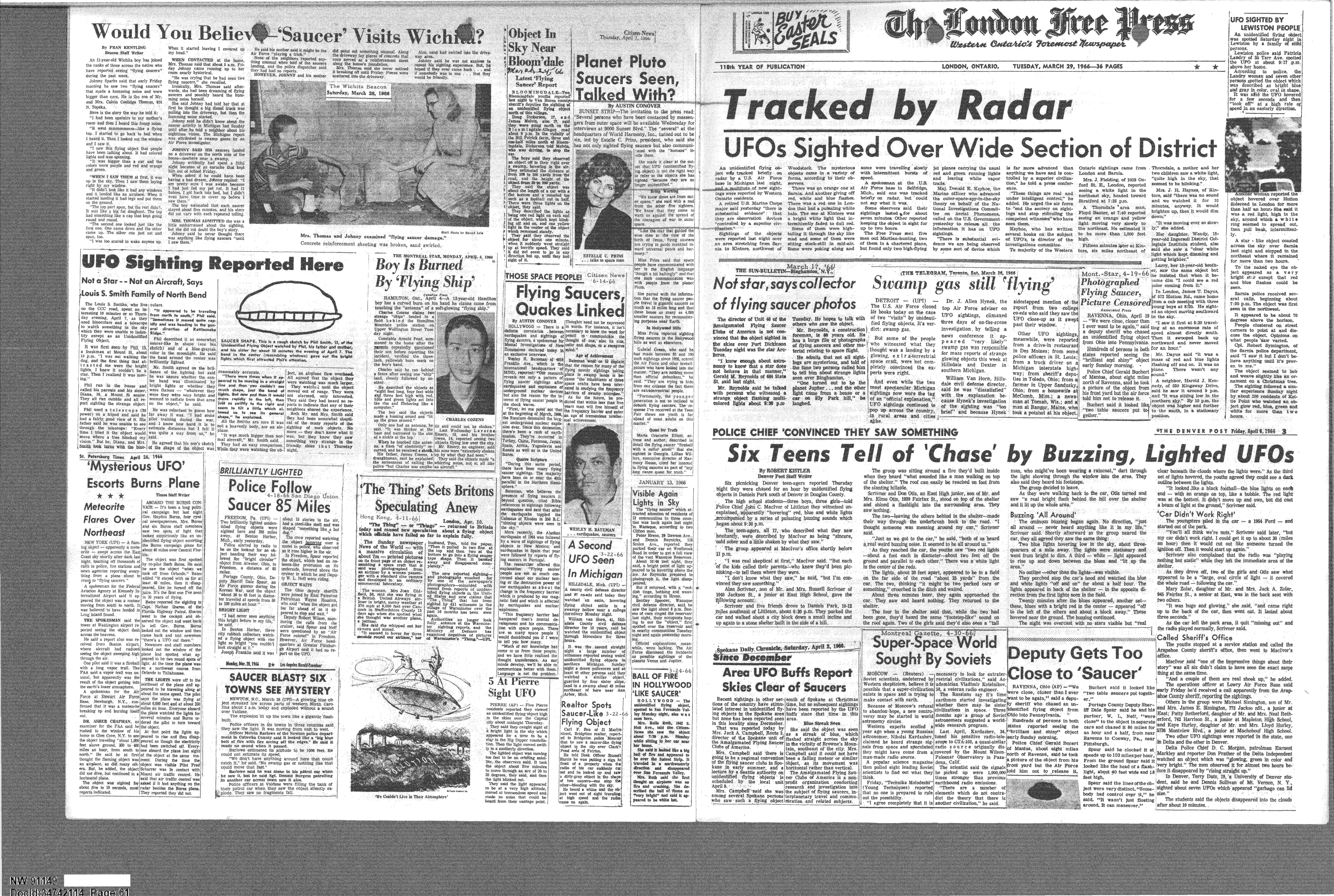
Collage of newspaper clippings about UFOs, primarily from The London Free Press, dated March 29, 1966. Headlines include 'Tracked by Radar', 'UFOs Sighted Over Wide Section of District', and 'Six Teens Tell of "Chase" by Buzzing, Lighted UFOs'.
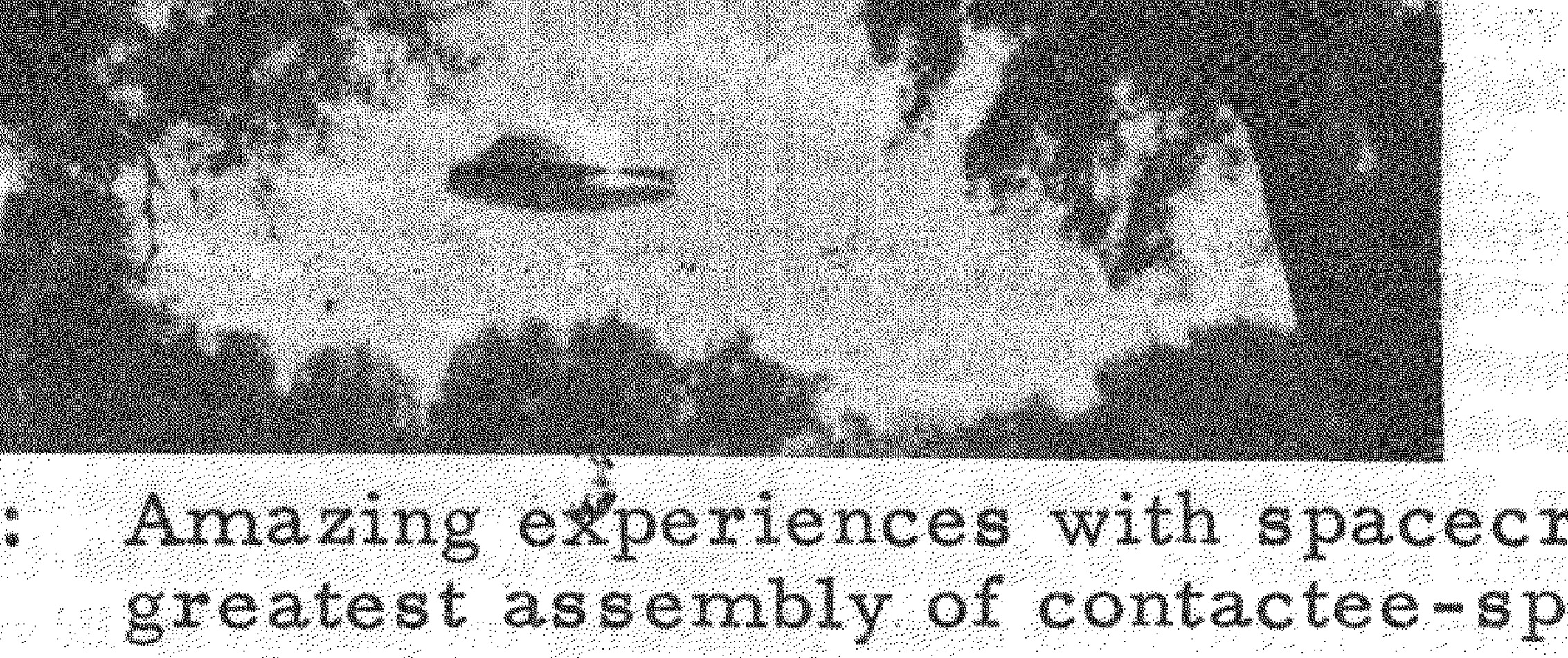
Photograph of a dark, disc-shaped object in the sky.
Photograph of a light-colored, disc-shaped object against a dark background.
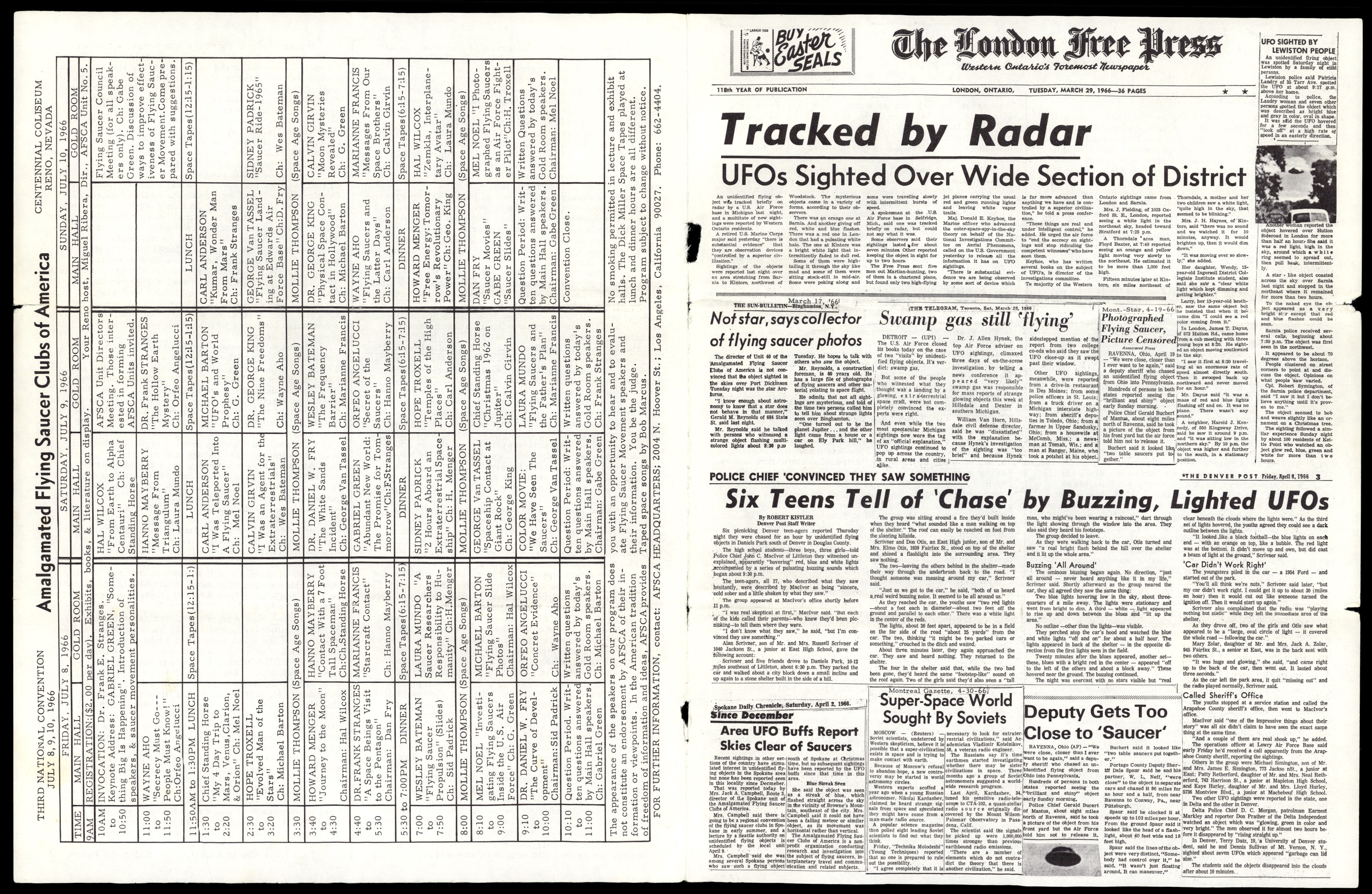
A collage of newspaper clippings and a convention schedule from the 'Flying Saucers International' magazine. The main headline is 'Tracked by Radar' from The London Free Press.
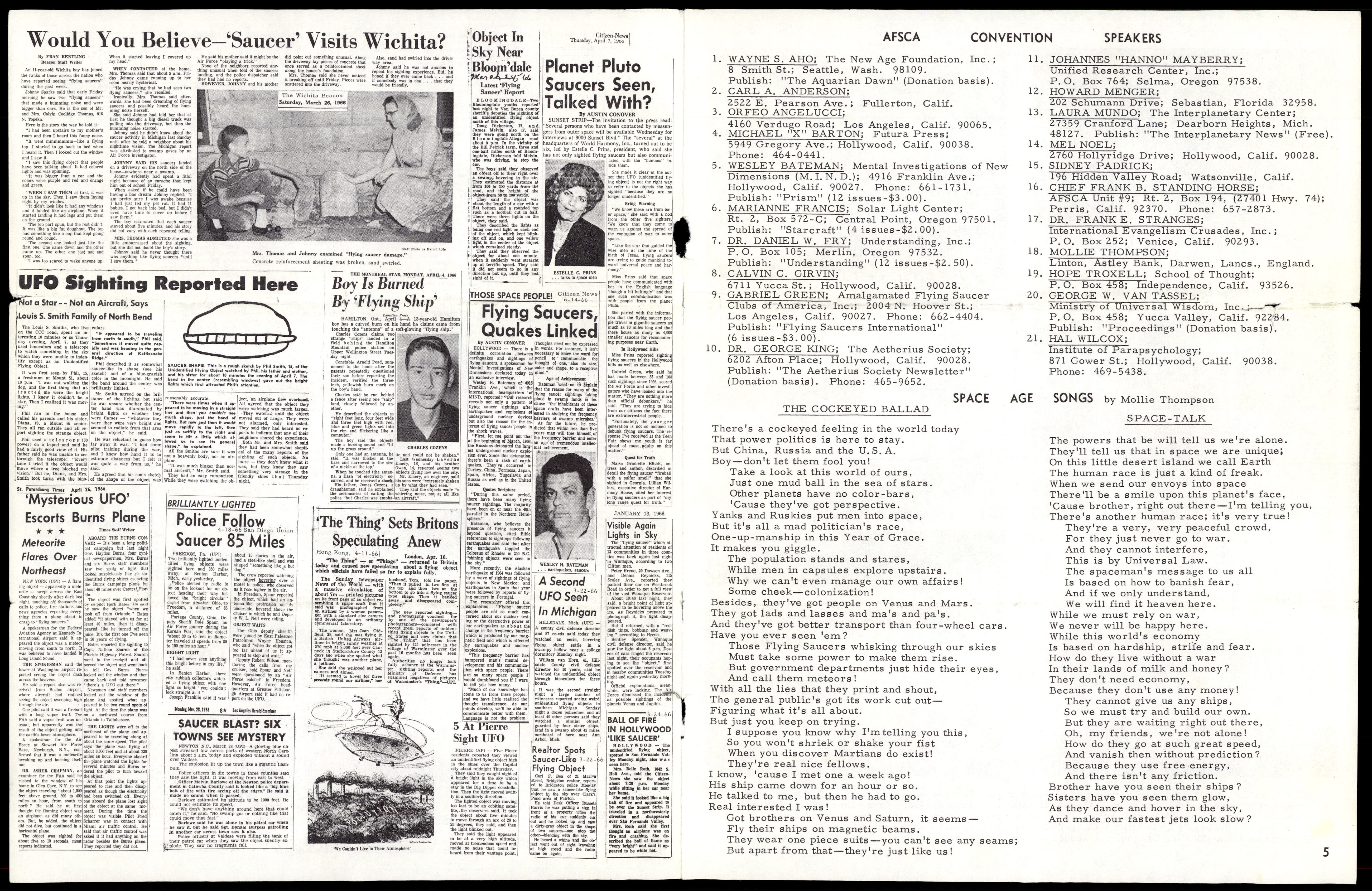
A collage of newspaper clippings from the 'Flying Saucers International' magazine, with headlines such as 'Would You Believe--"Saucer" Visits Wichita?' and 'Boy Is 'Burned' By 'Flying Ship'.
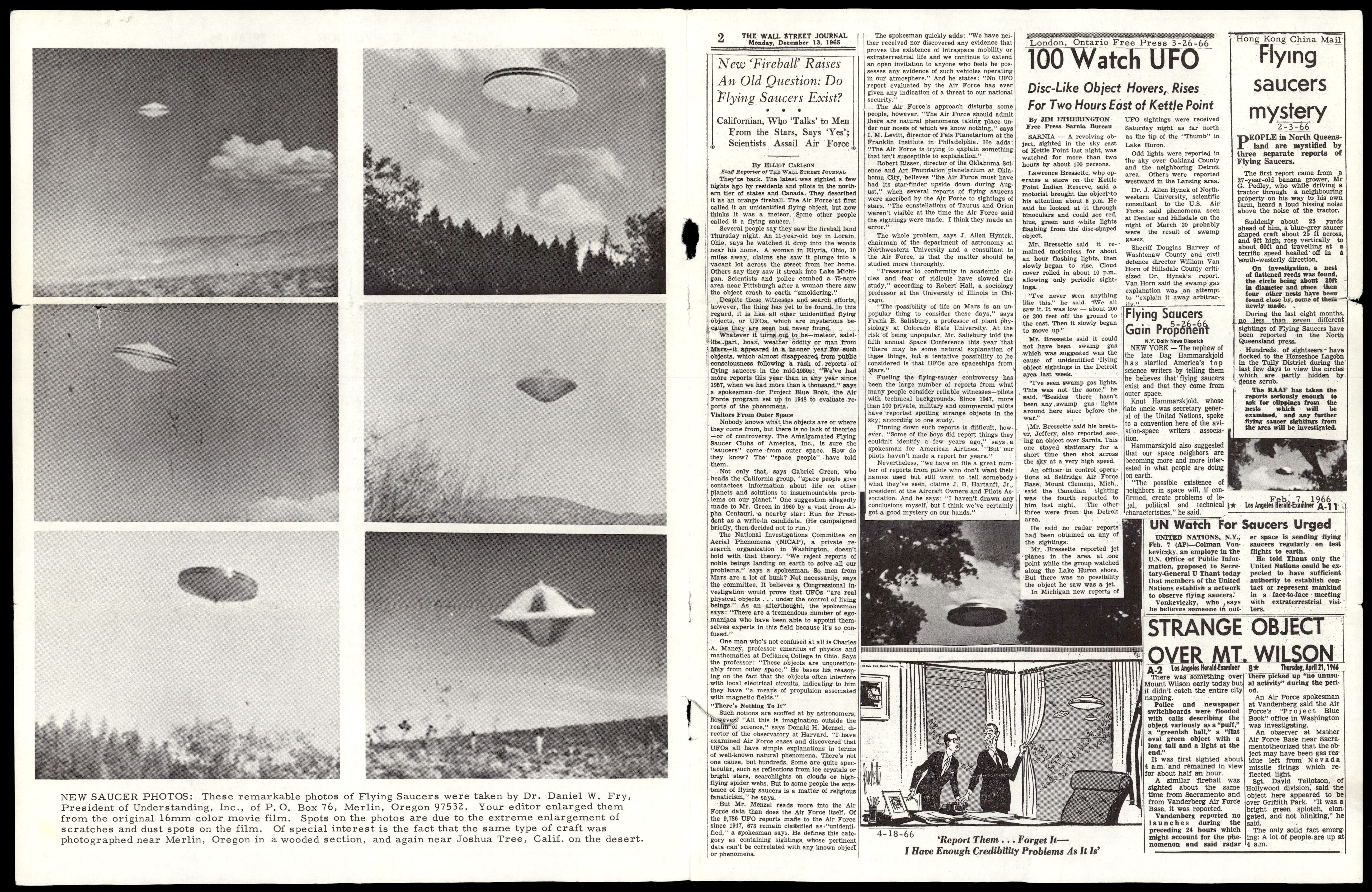
A collage of newspaper clippings and UFO photographs from the 'Flying Saucers International' magazine. Headlines include 'New 'Fireball' Raises An Old Question: Do Flying Saucers Exist?' and '100 Watch UFO'.
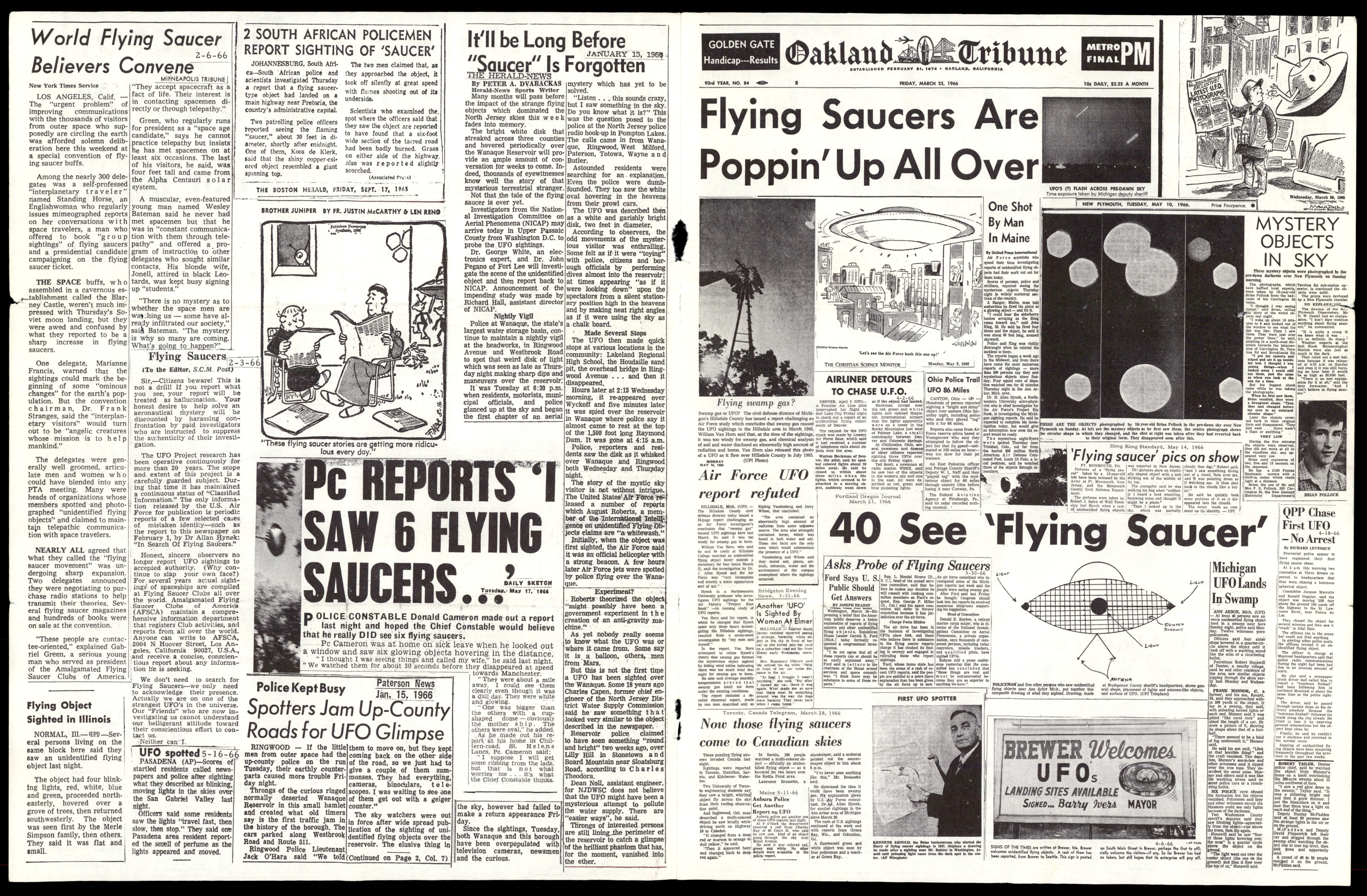
A collage of newspaper clippings from the 'Flying Saucers International' magazine, with a large headline from the Oakland Tribune: 'Flying Saucers Are Poppin' Up All Over'.

A collage of newspaper clippings from the 'Flying Saucers International' magazine, with headlines such as 'Civil Defense Director Watches 'Flying Saucer'' and 'Who's In All Those Saucers?'.
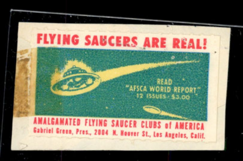
A promotional card for the Amalgamated Flying Saucer Clubs of America, featuring an illustration of a flying saucer.
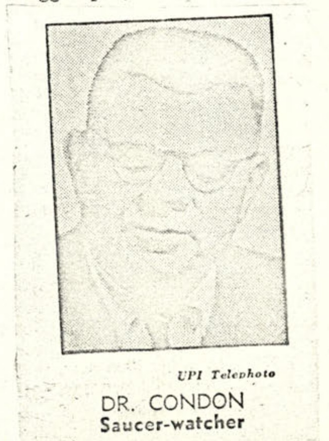
UPI Telephoto DR. CONDON Saucer-watcher
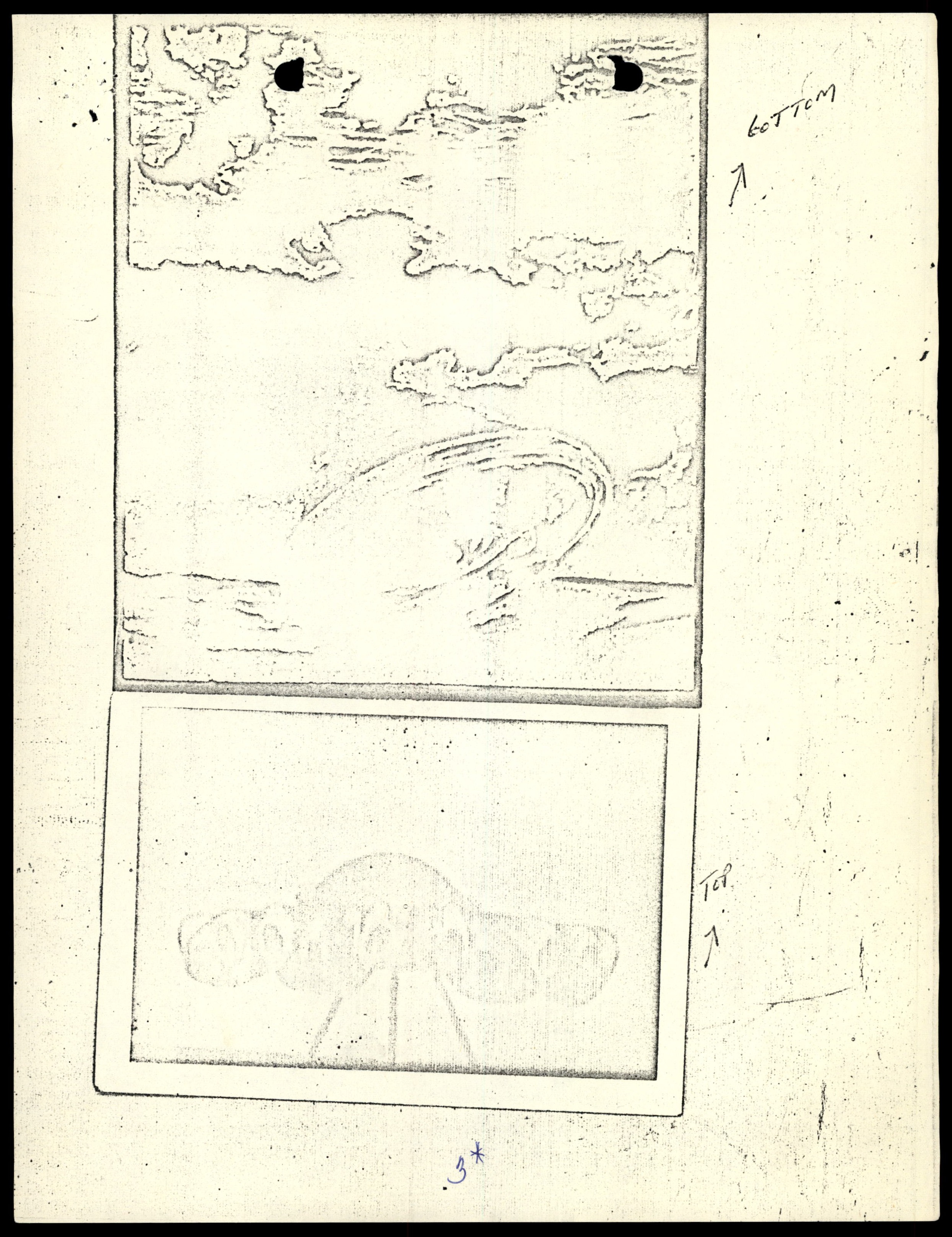
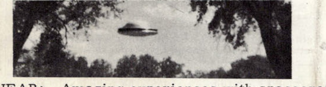
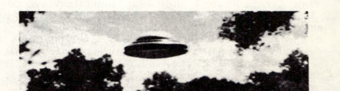
Xerox copy of a photograph showing a saucer-shaped object in flight against a cloudy sky.
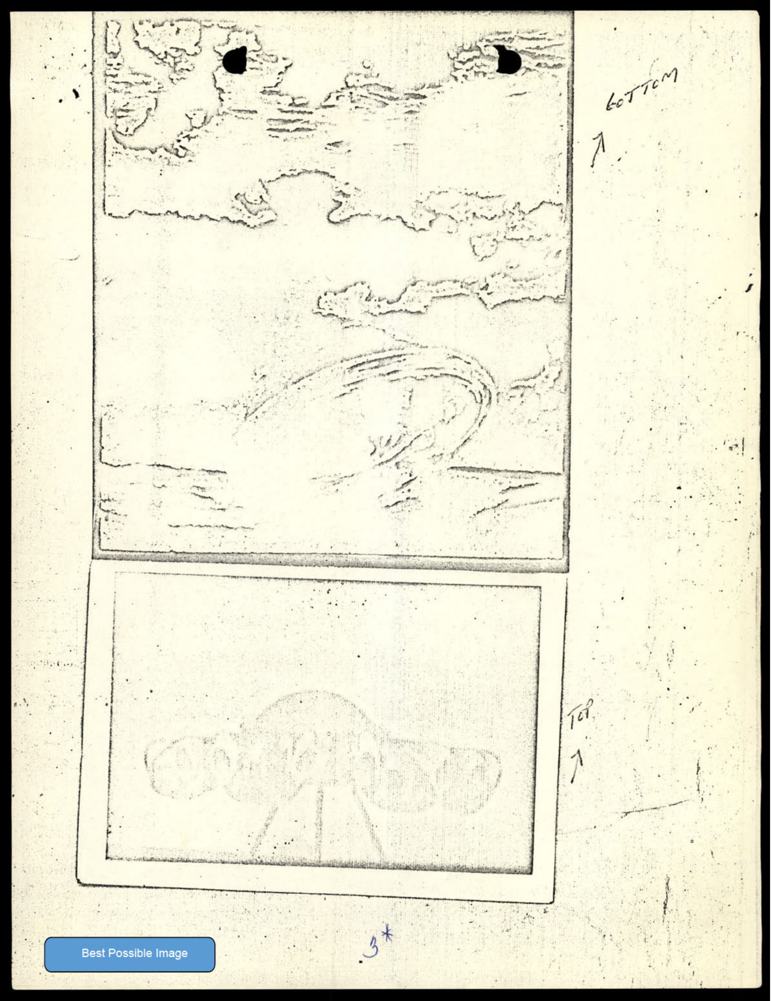
Xerox copy of a photograph showing a saucer-shaped object in flight against a cloudy sky.
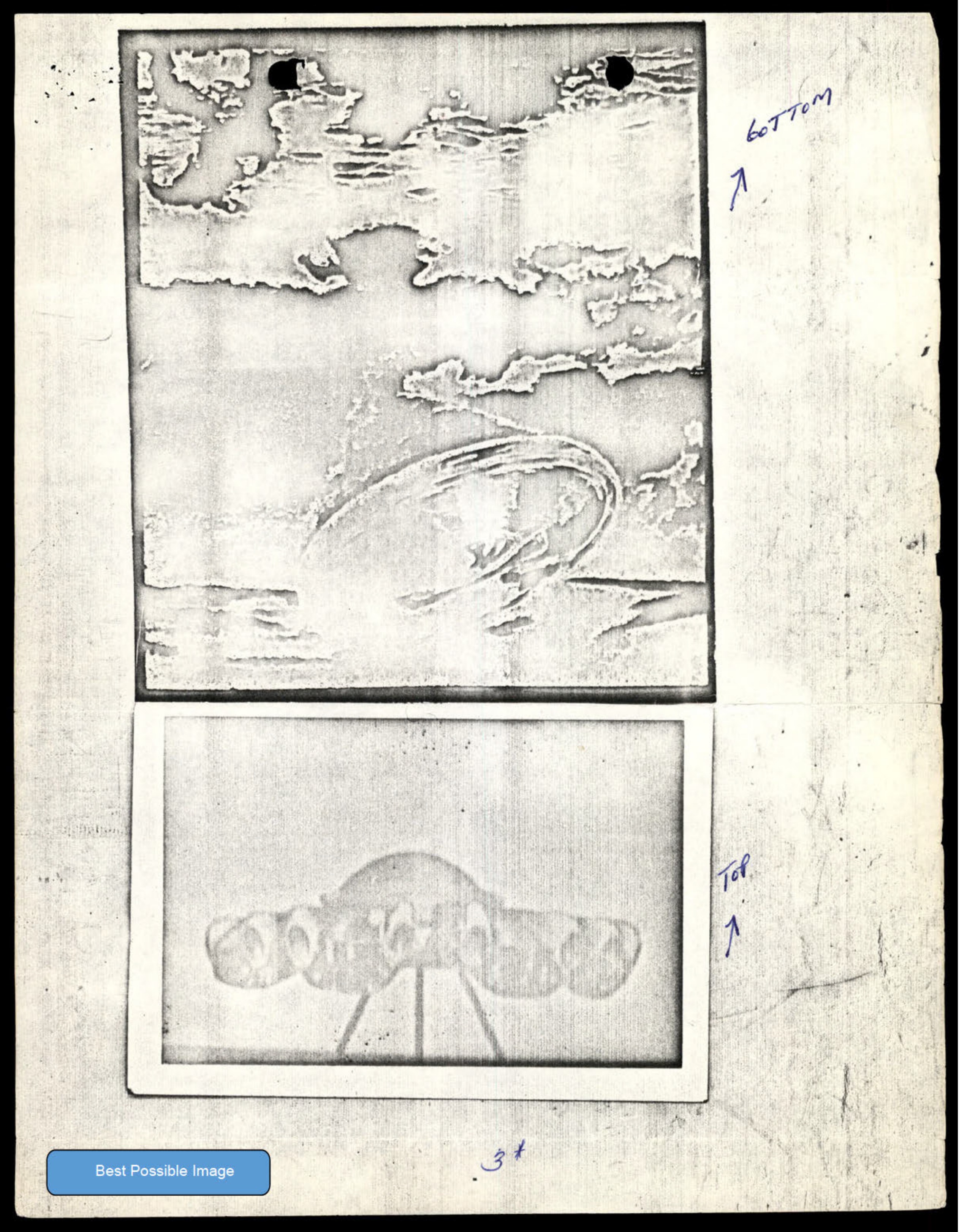
Xerox copy of a photograph showing a saucer-shaped object in flight against a cloudy sky.
Abstract graphic design on the cover of the journal.
A photograph of a disc-shaped object in the sky.
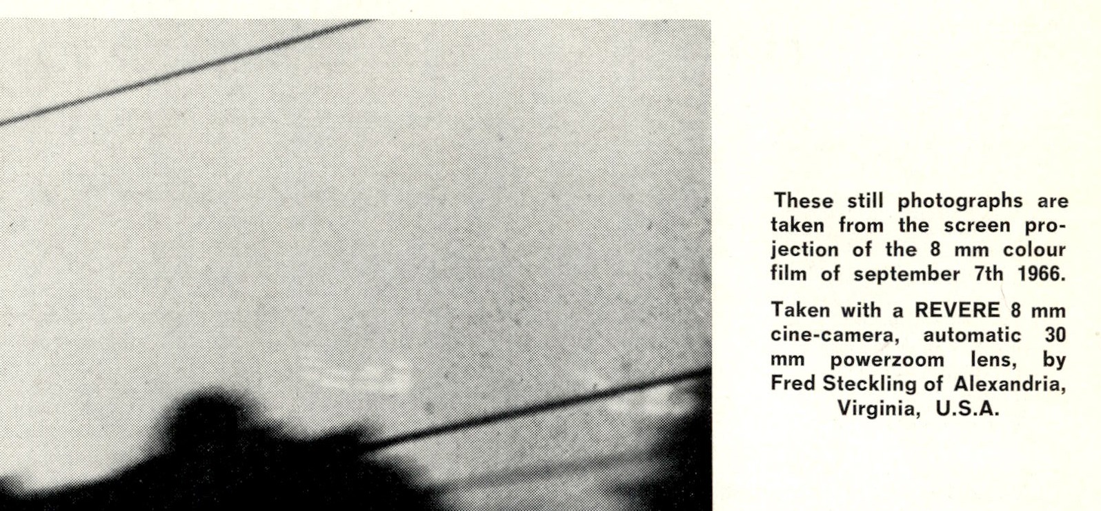
Still photograph from 8mm film showing objects in the sky.
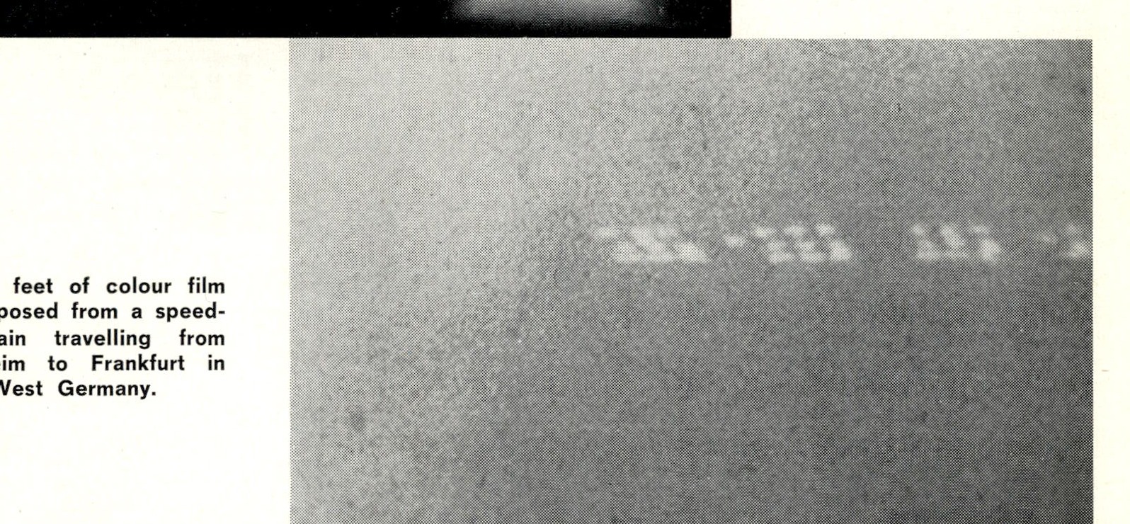
Still photograph from 8mm film showing objects in the sky.
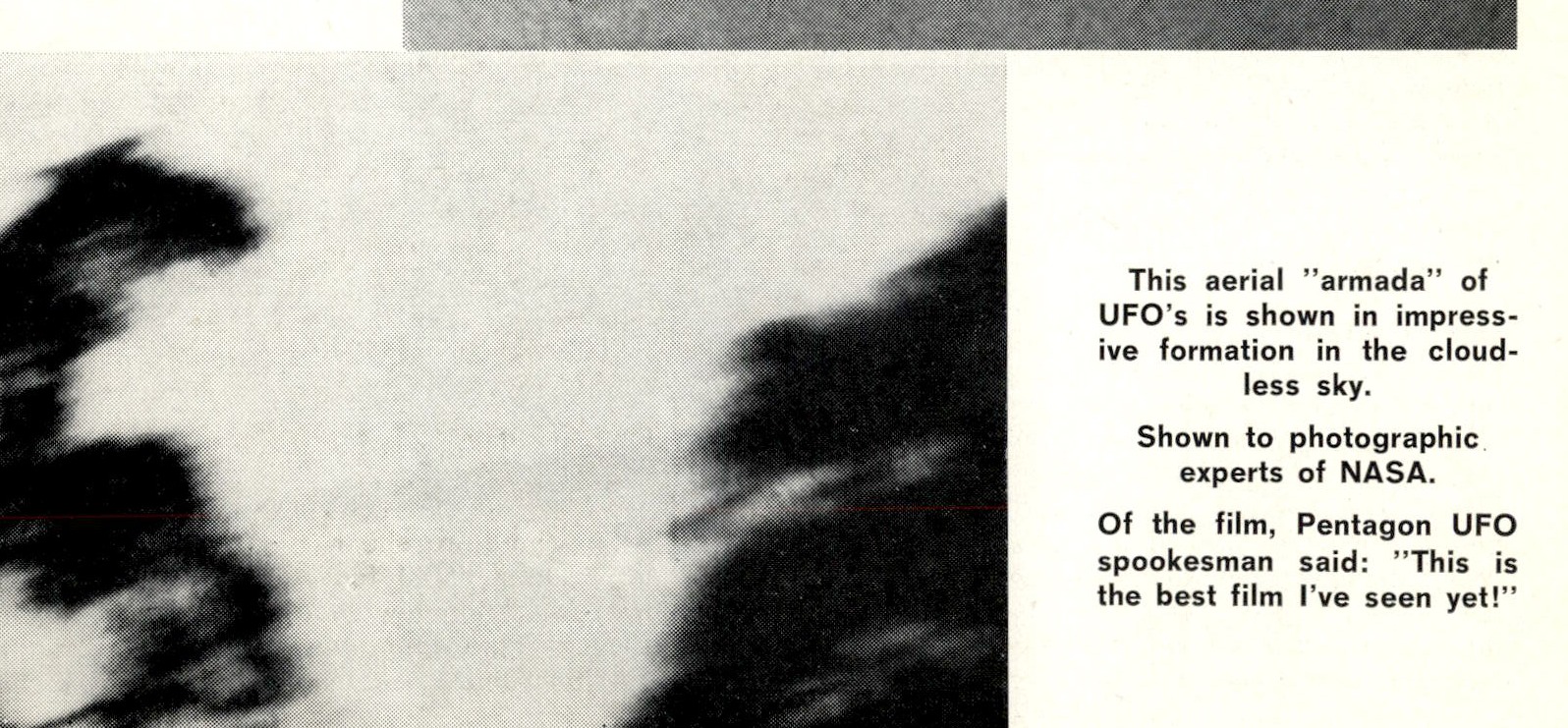
Still photograph from 8mm film showing objects in the sky.
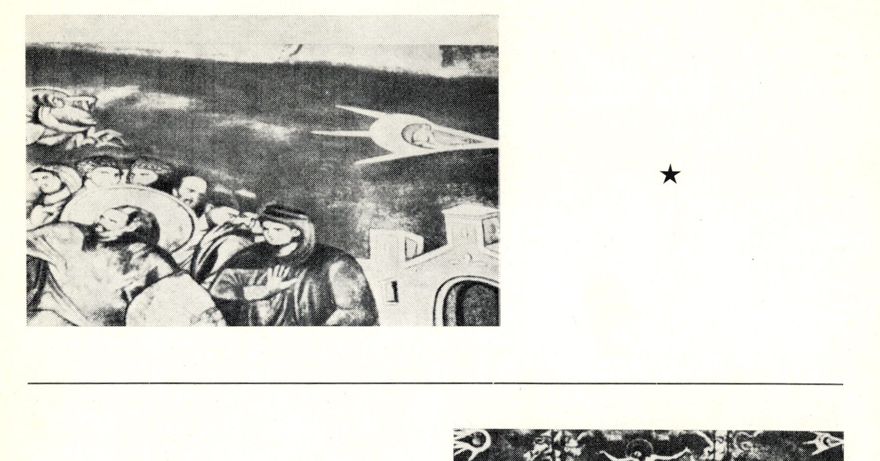
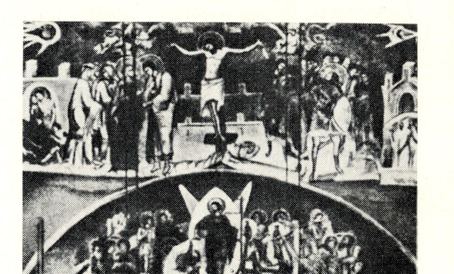
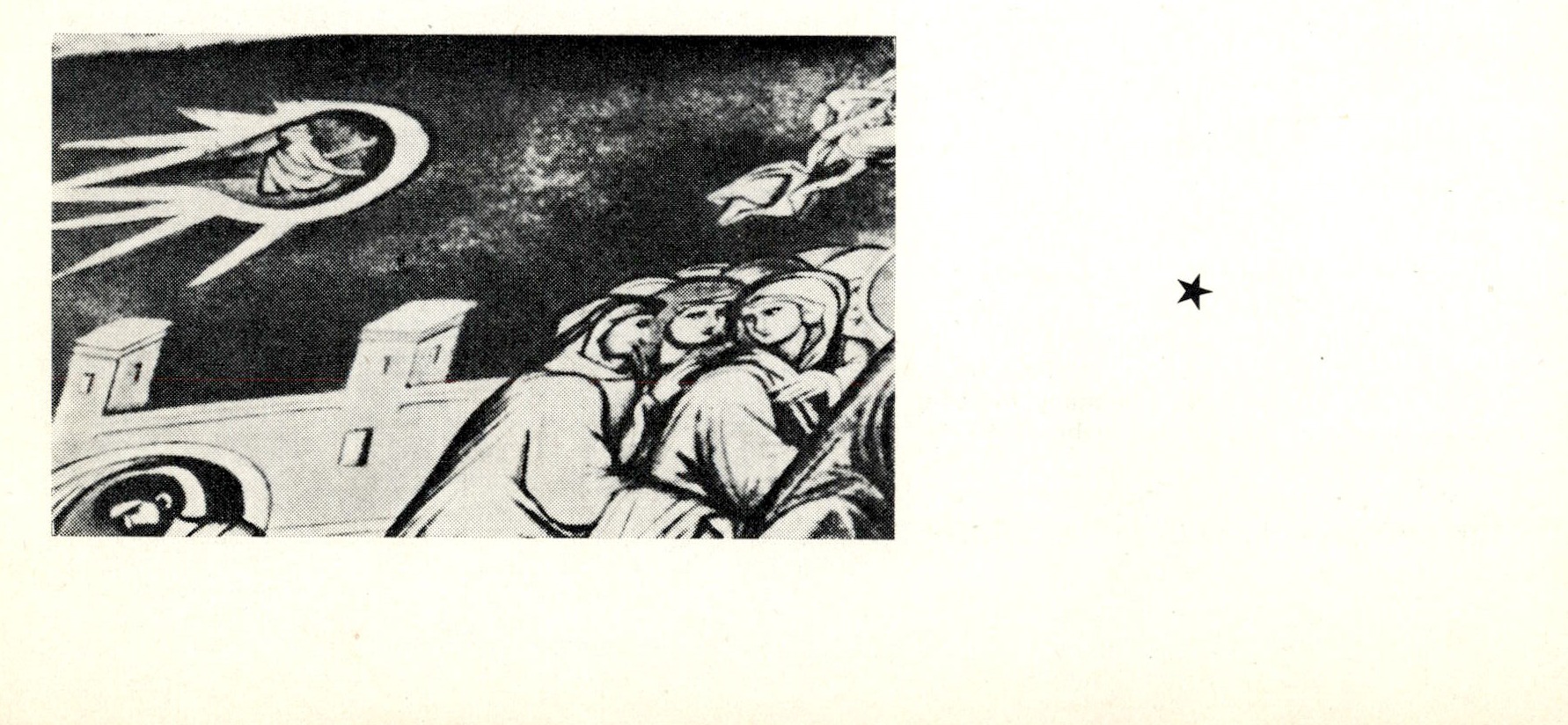
Fresco in the Dechany Monastery (Yugoslavia). The angels look as if they were flying in spacecraft.
The icon, "The Resurrection of our Lord Jesus Christ". (17th century) from the Moscow Theological Academy. "The House of the Lord" resembles a space ship.
—
Faint, high-contrast image of a skeletal or emaciated humanoid figure with arms raised.
Negative image of a memorandum.
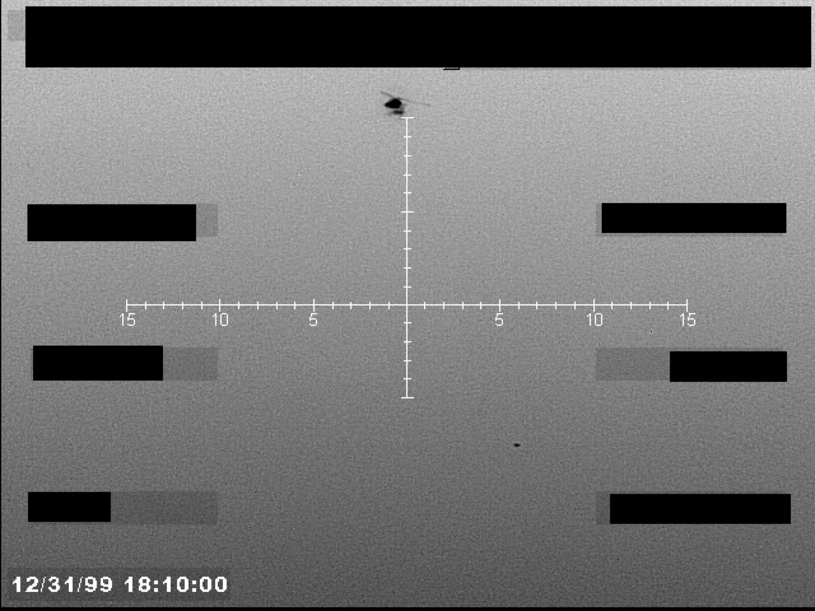
Sensor display, possibly FLIR, showing a targeting crosshair with a small, dark, unidentified object near the center. A timestamp is visible in the lower-left corner.
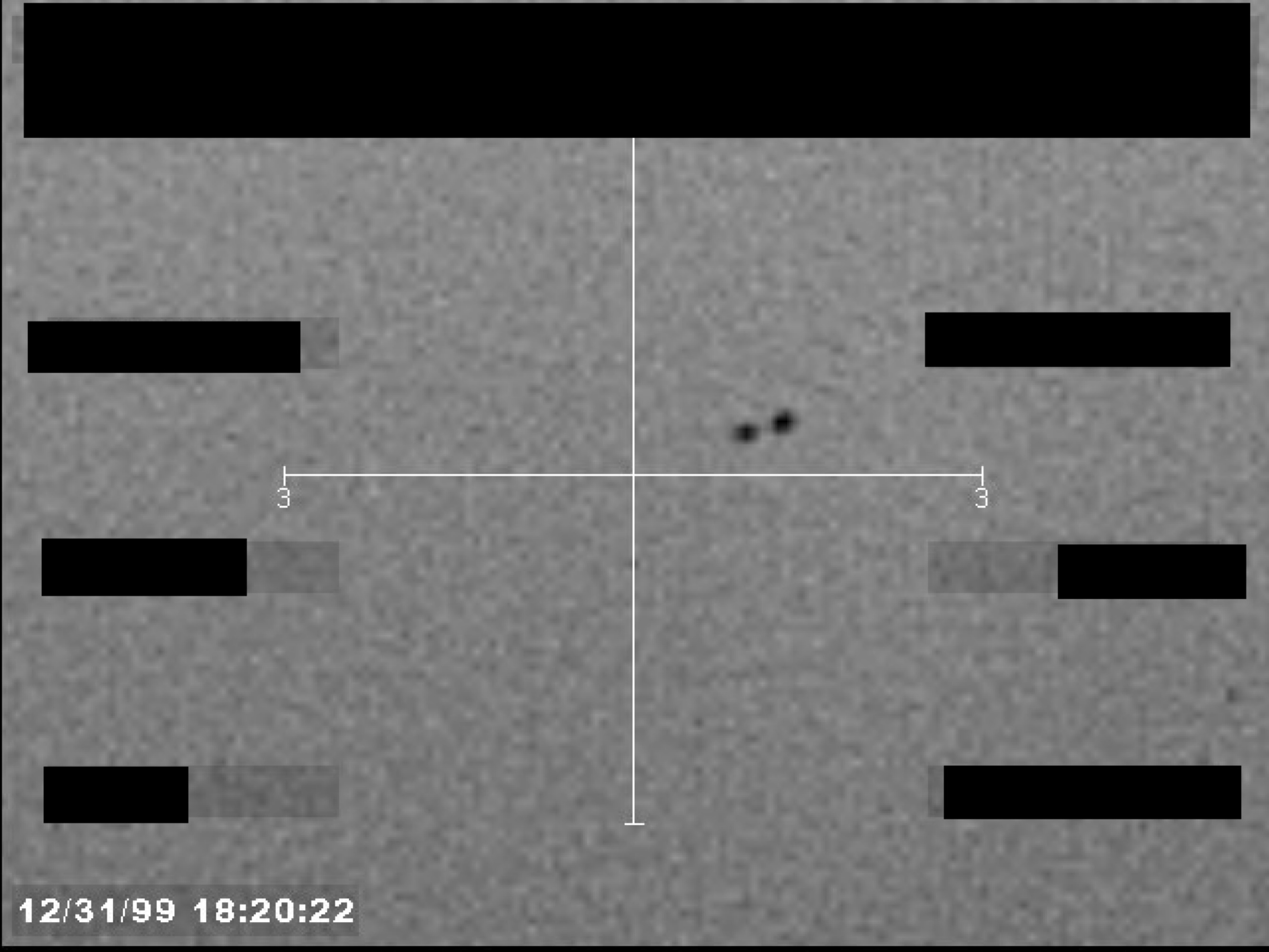
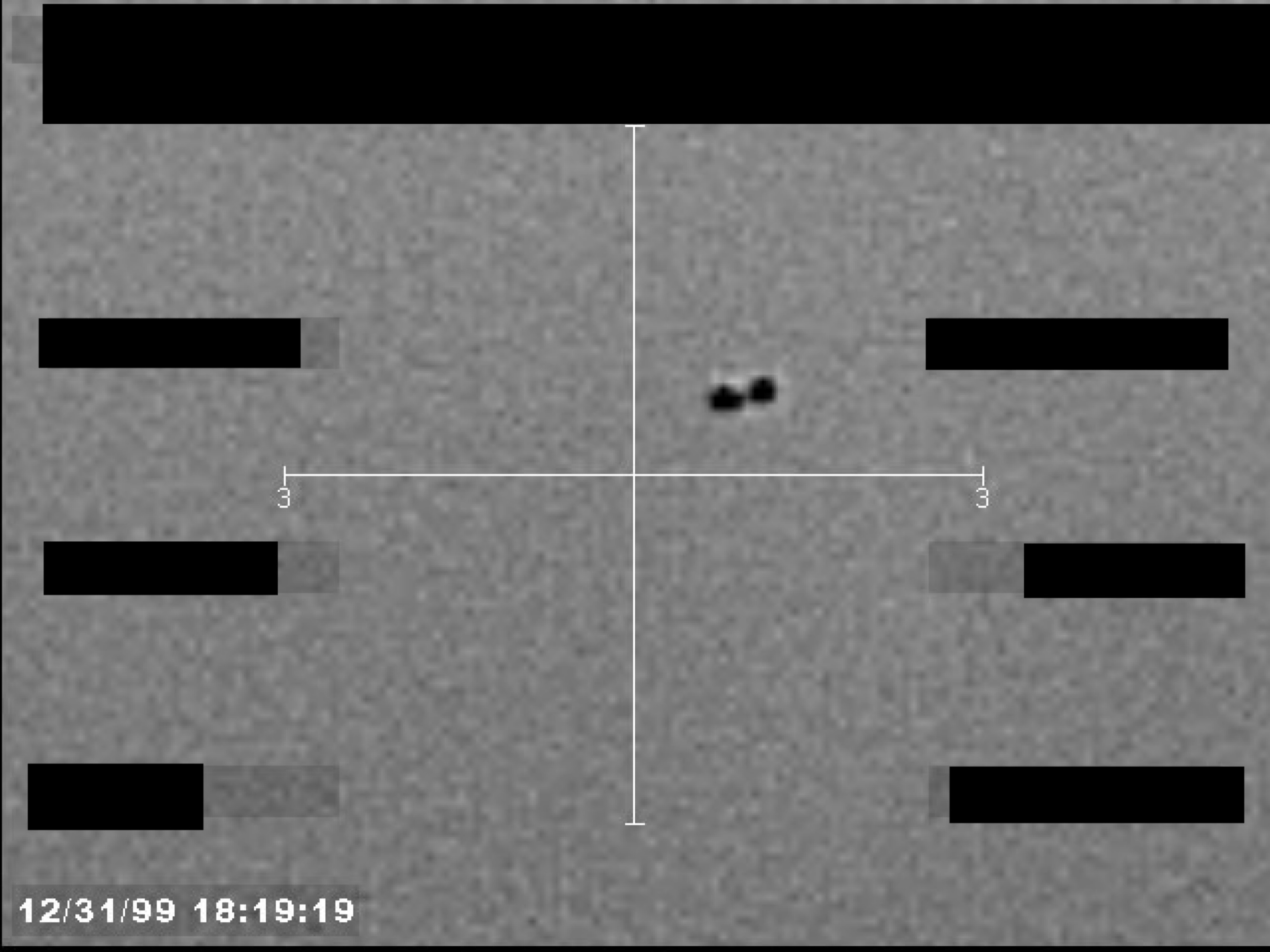
A grainy, black-and-white image from a sensor or camera, showing a crosshair centered on two small, dark objects. A timestamp is visible in the lower-left corner.
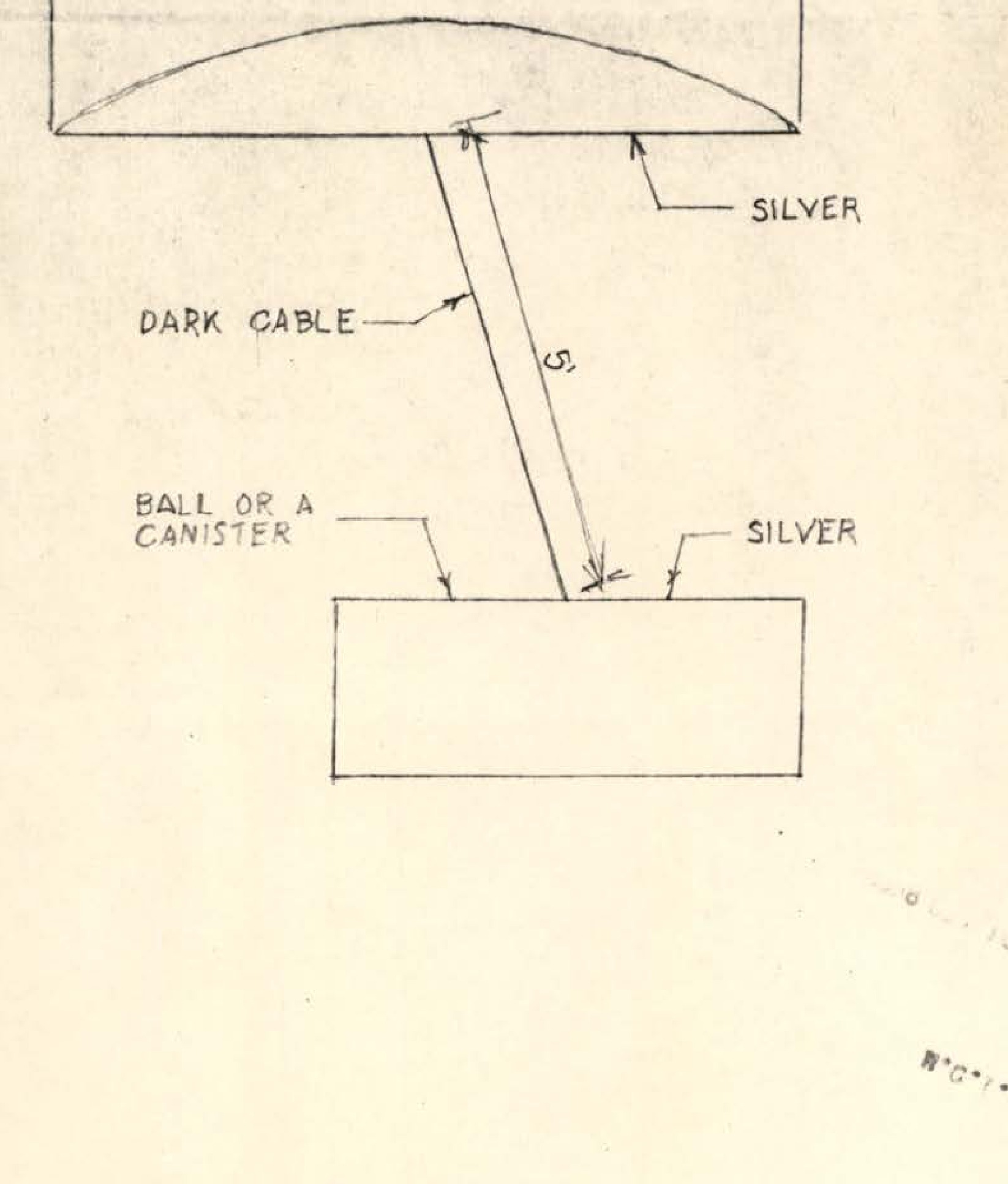
Technical diagram showing an 8-foot silver object connected by a 5-foot dark cable to a ball or canister below, with silver components labeled
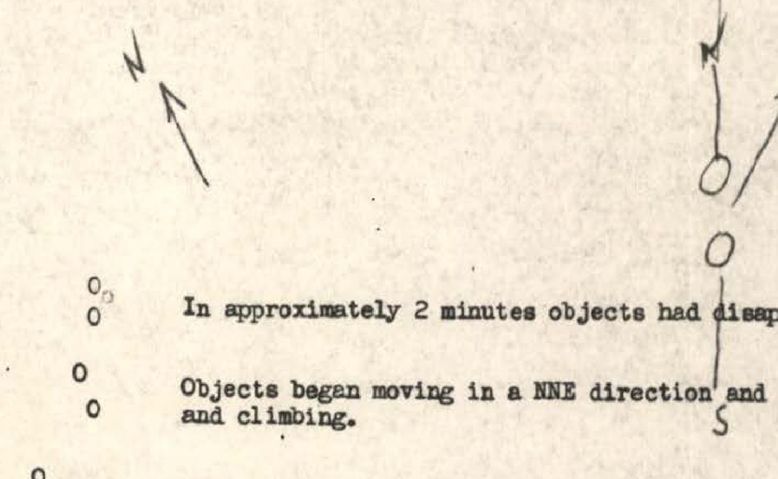
Hand-drawn diagram showing object movement sequence with arrows and circles
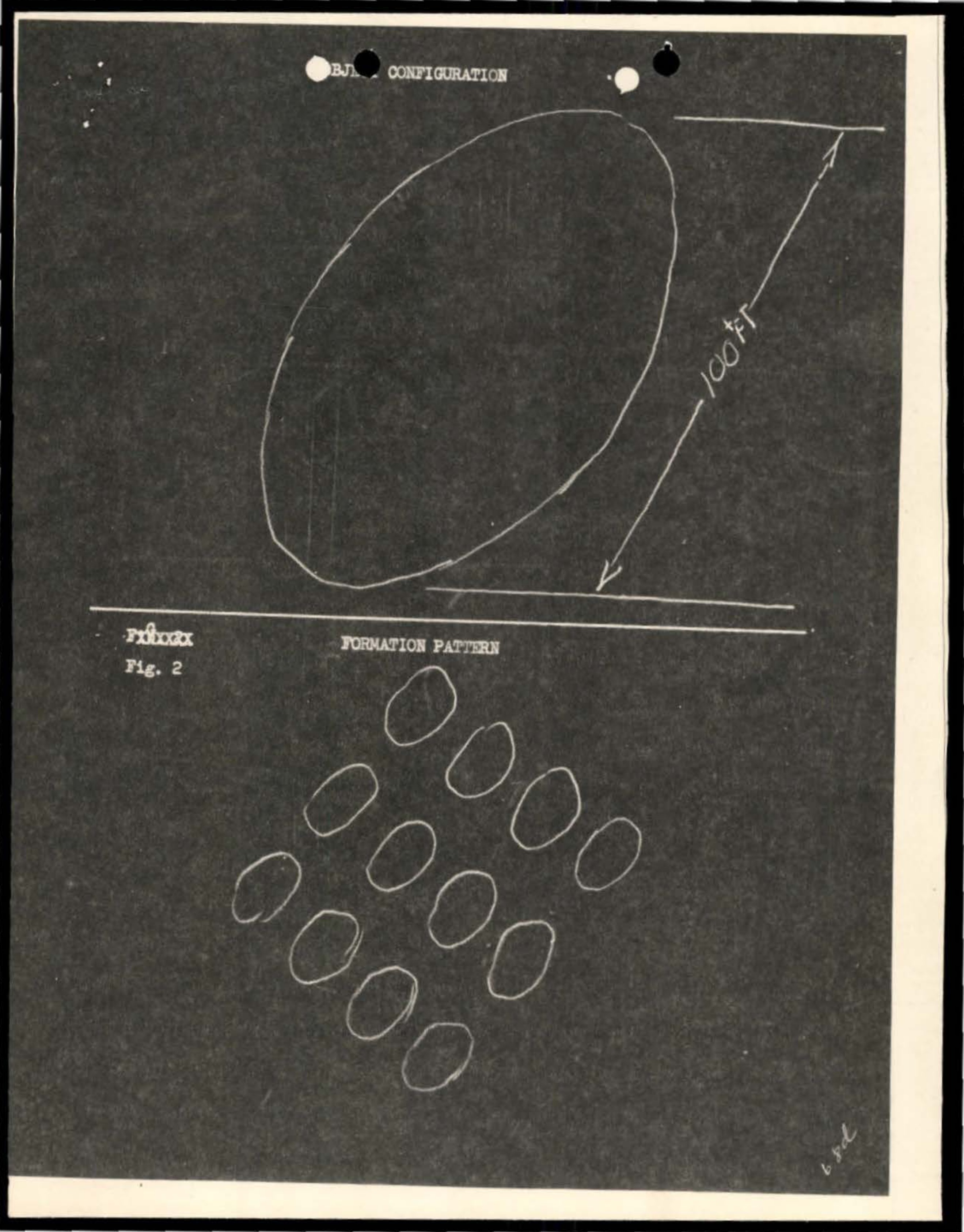
Object configuration showing oval/elliptical shape with directional arrow marked 100 YA
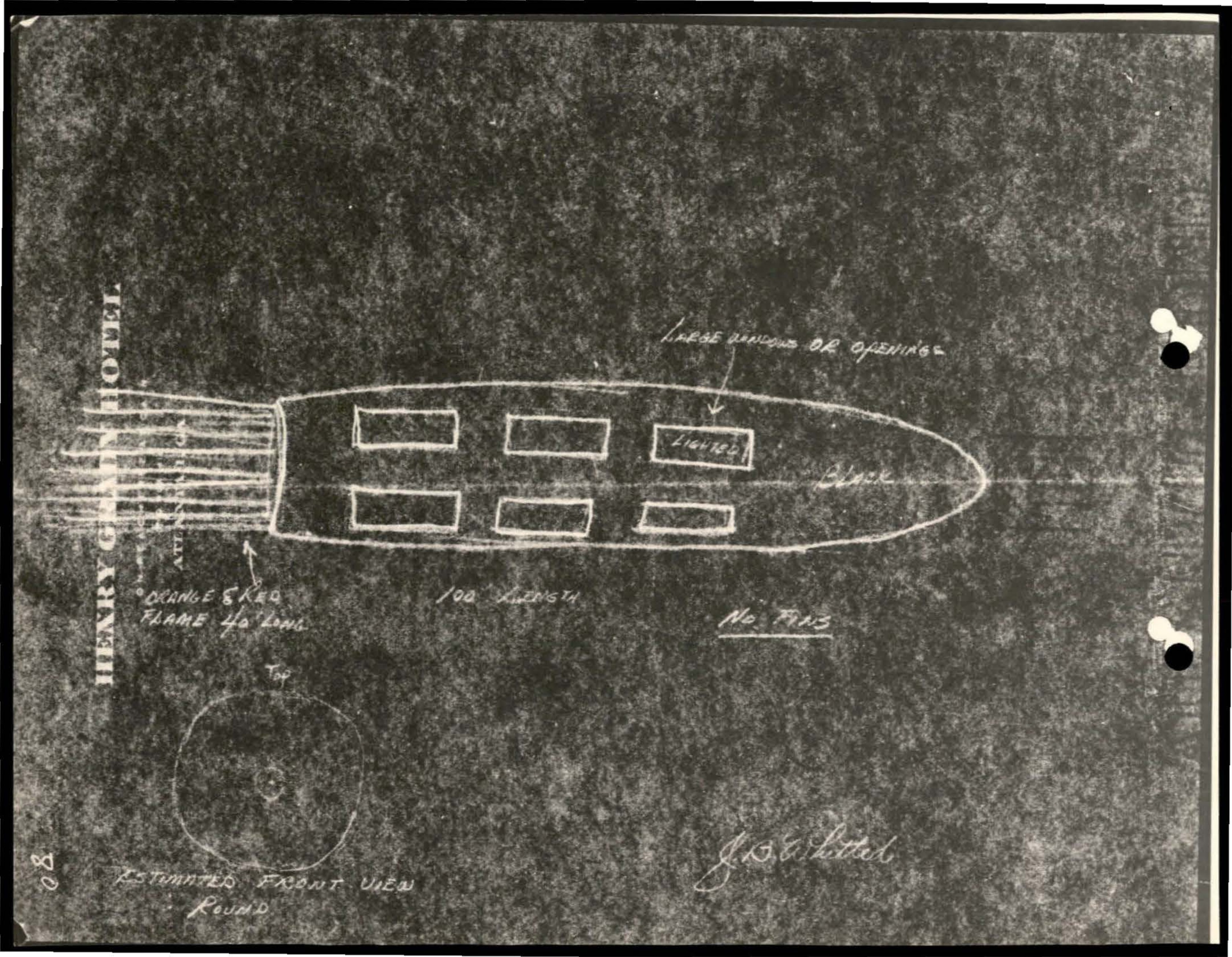
Diagram of vessel or object with compartments and hawser attachment
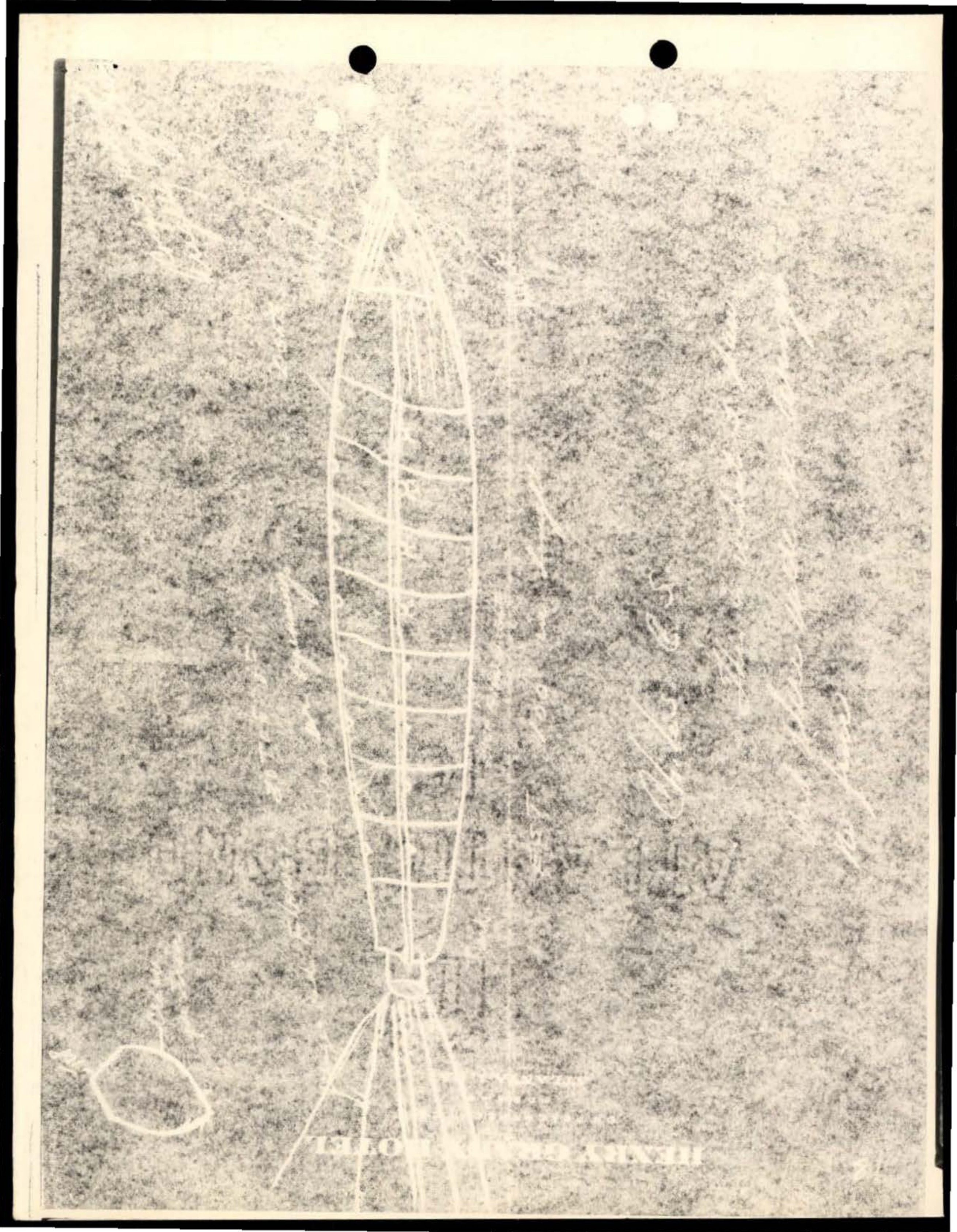
White line drawing or sketch on grainy/textured background showing what appears to be a ladder-like or tower structure with geometric patterns
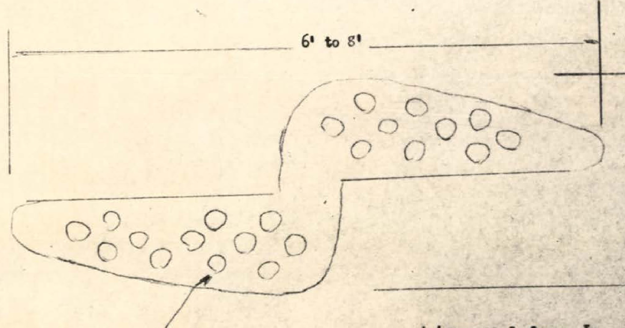
Technical diagram showing object dimensions 6' to 8' width and 1/2' to 2' height with circular protrusions
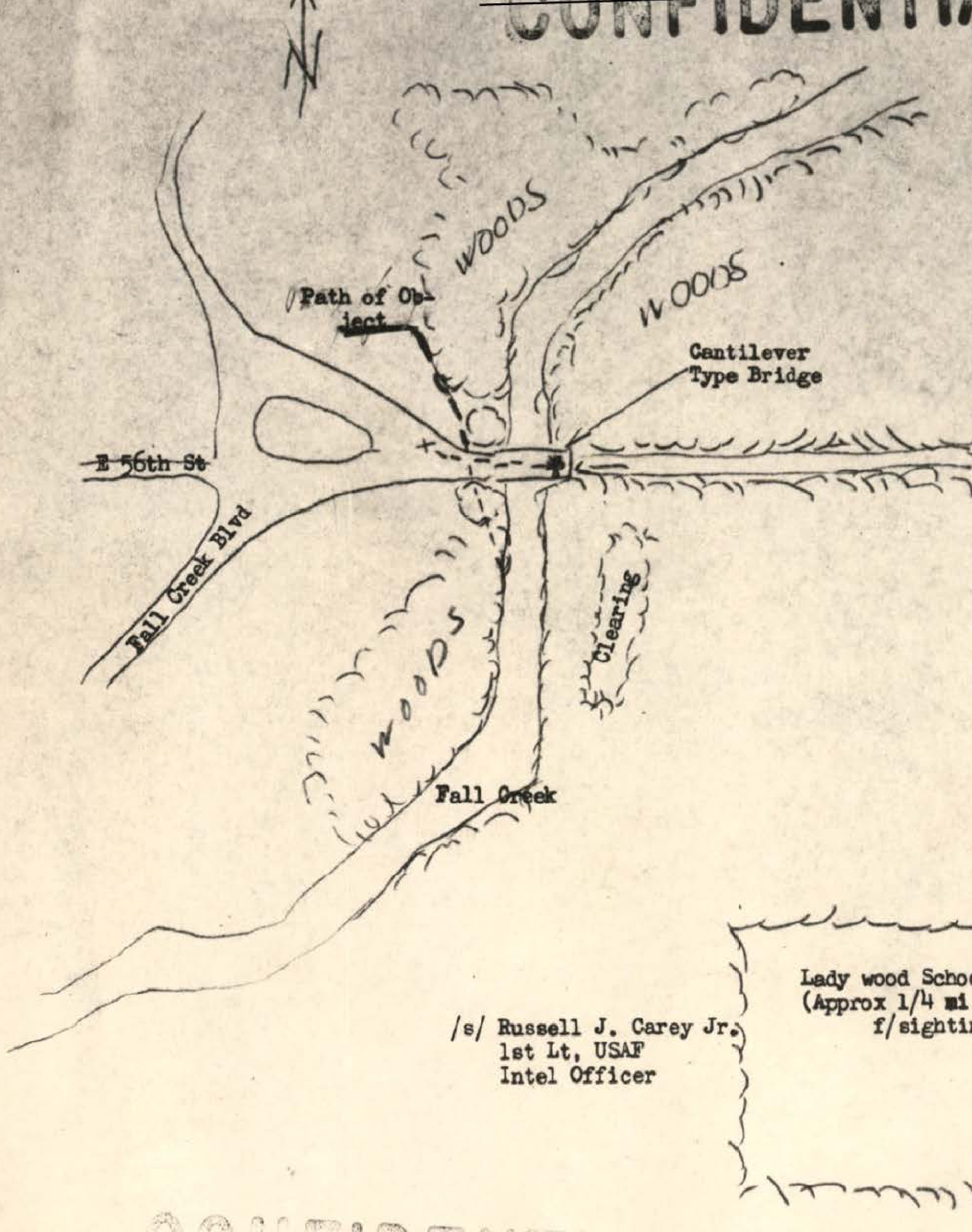
Hand-drawn map showing path of object, roads (E 96th St, Fall Creek Blvd), wooded areas, cantilever bridge, and Lady wood School location
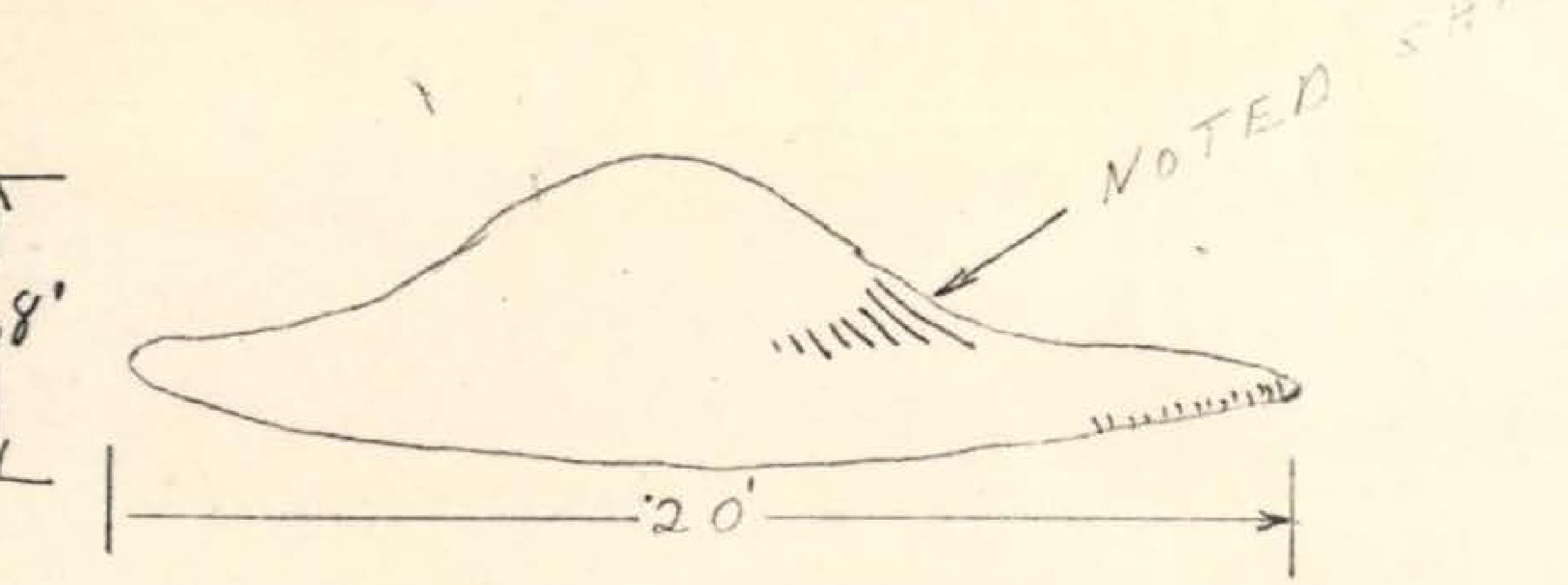
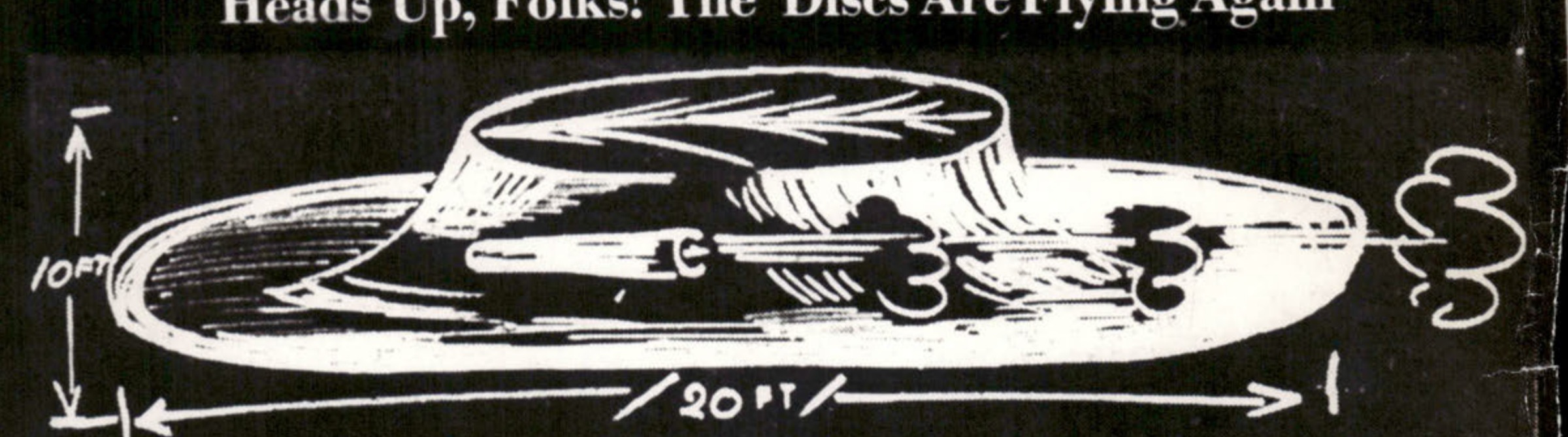
Technical sketch of disc-shaped object showing dimensions: 6 to 8 feet height, 20 feet width, with notation for seating area
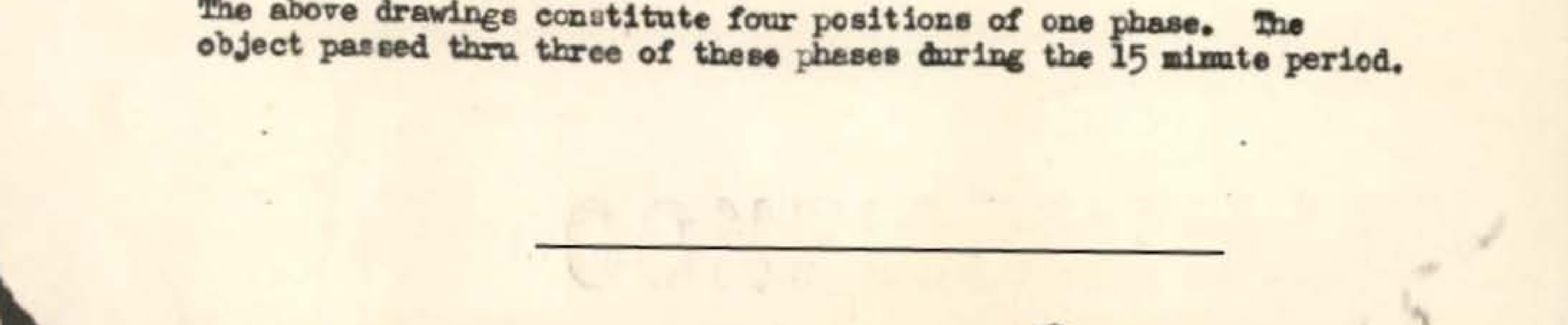
Four sketches showing different positions/shapes of observed object labeled Fourth, Third, Second, First
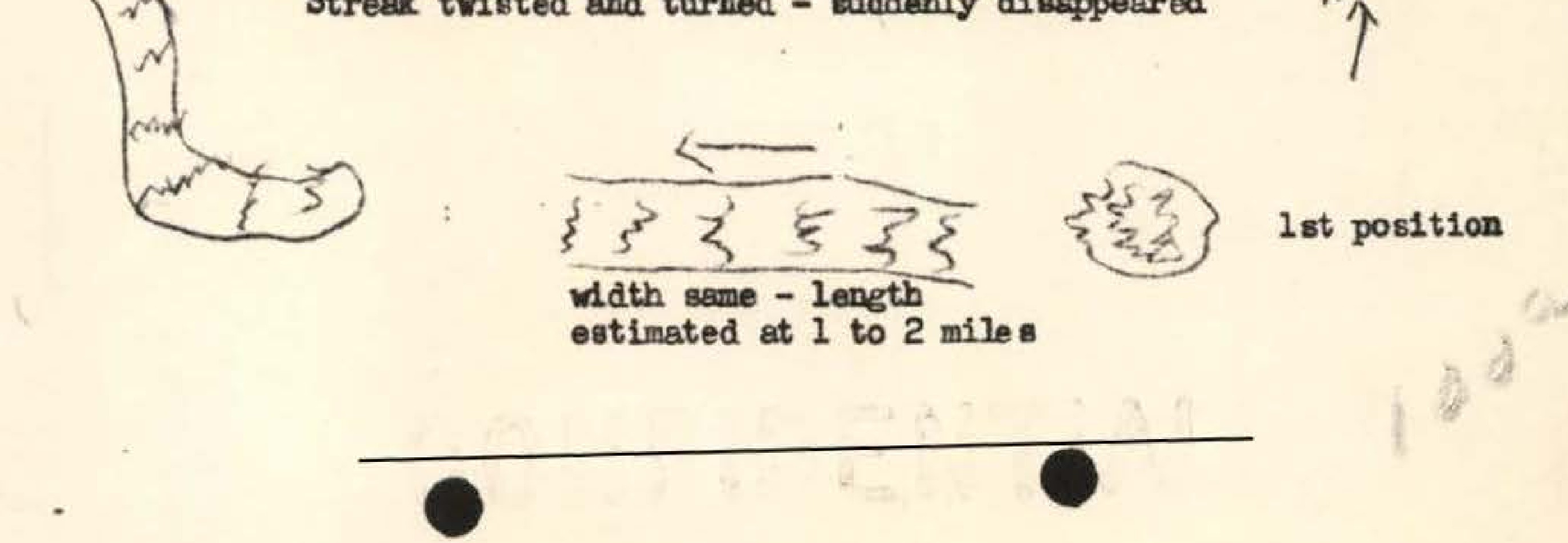
Hand-drawn sketches showing the progression of the observed phenomenon with directional arrow and position markers

RTI logo
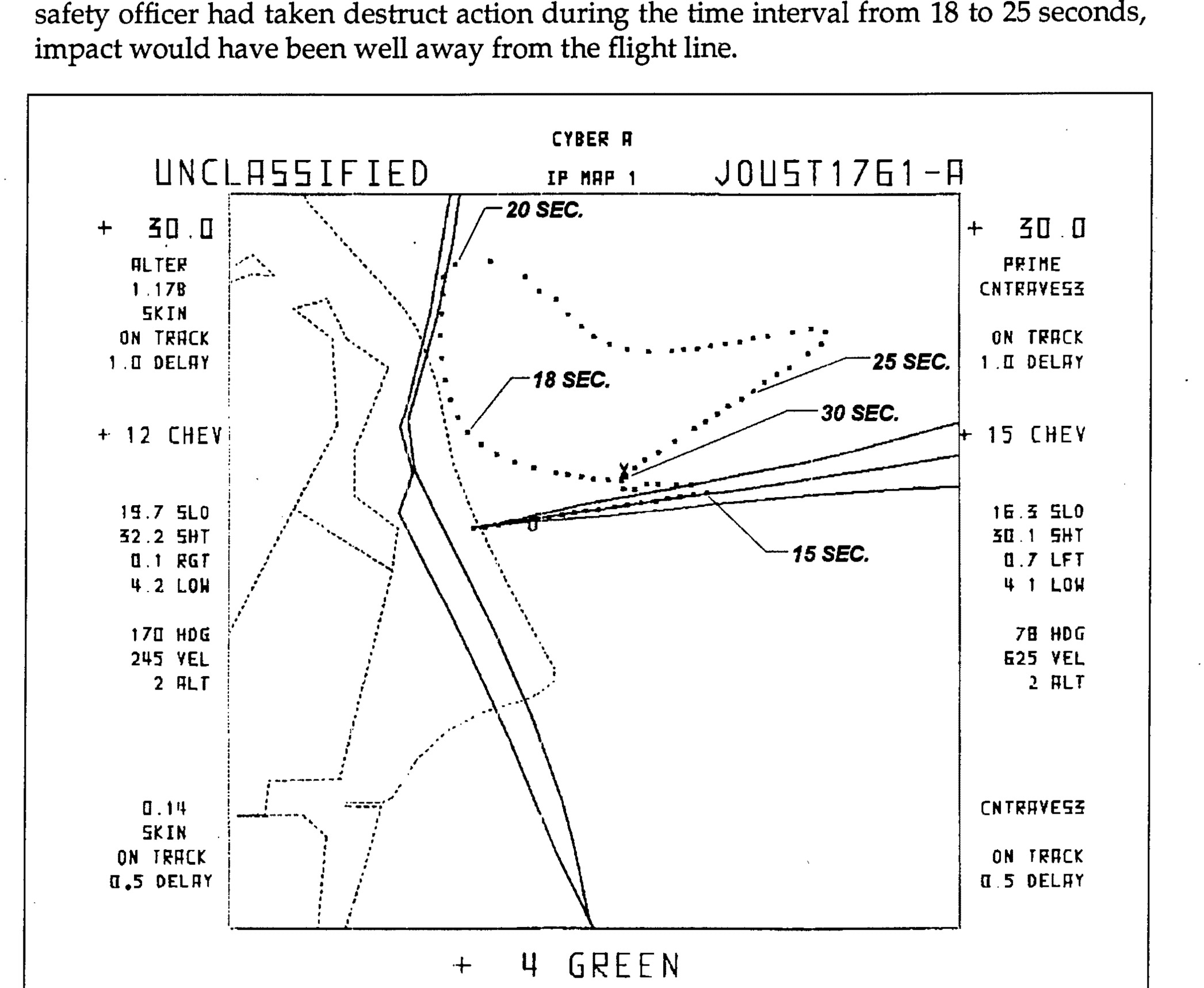
Figure 1. Joust Impact Trace Showing a Mode-5 Failure Response - UNCLASSIFIED CYBER H IP MAP 1 JOUST1761-A diagram showing trajectory traces at various time intervals (18 SEC, 20 SEC, 25 SEC, 30 SEC) with technical parameters including altitude, velocity, and track data
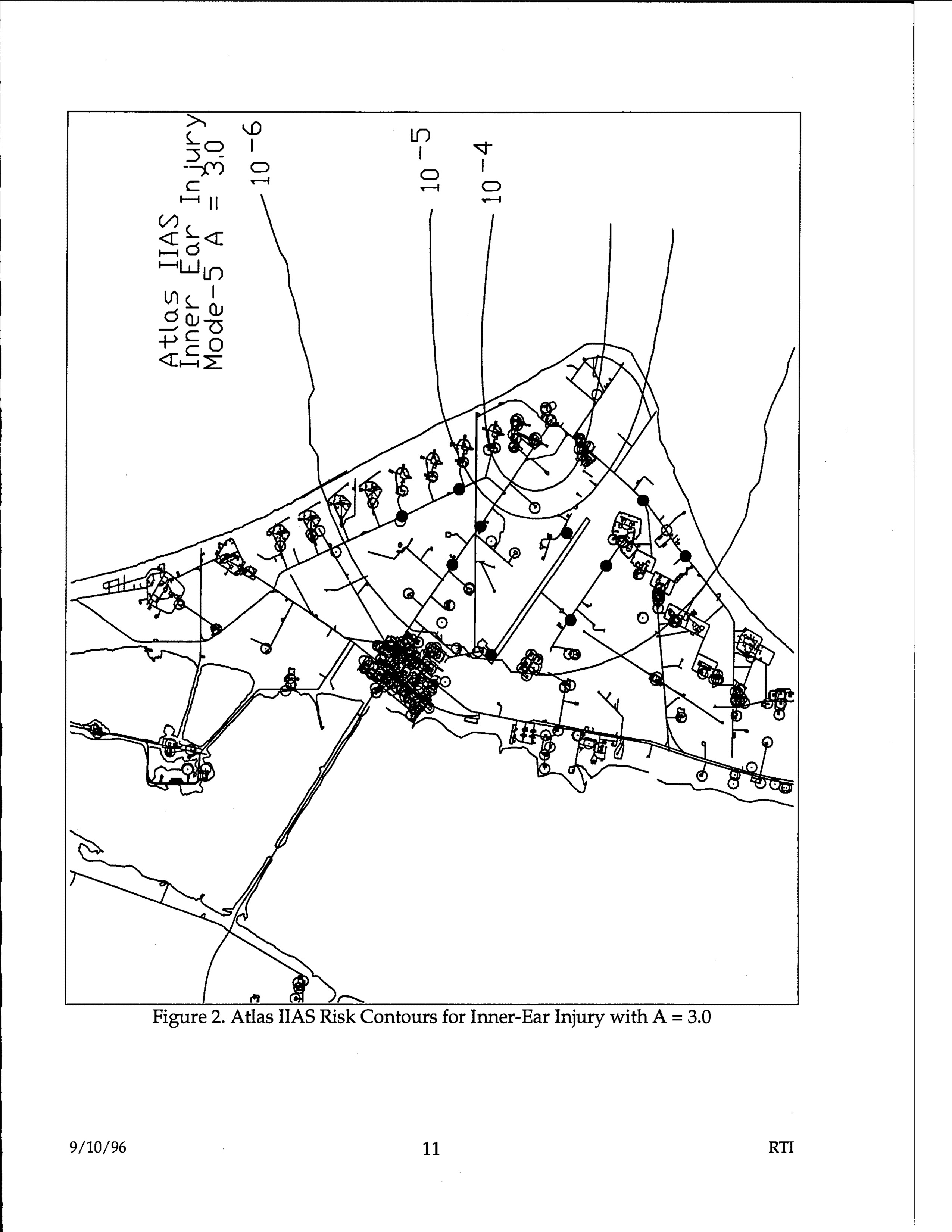
Atlas IIAS risk contours map showing inner-ear injury zones with concentric circles marked 10^-6, 10^-5, and 10^-4, with Mode-5A notation and A=3.0 parameter
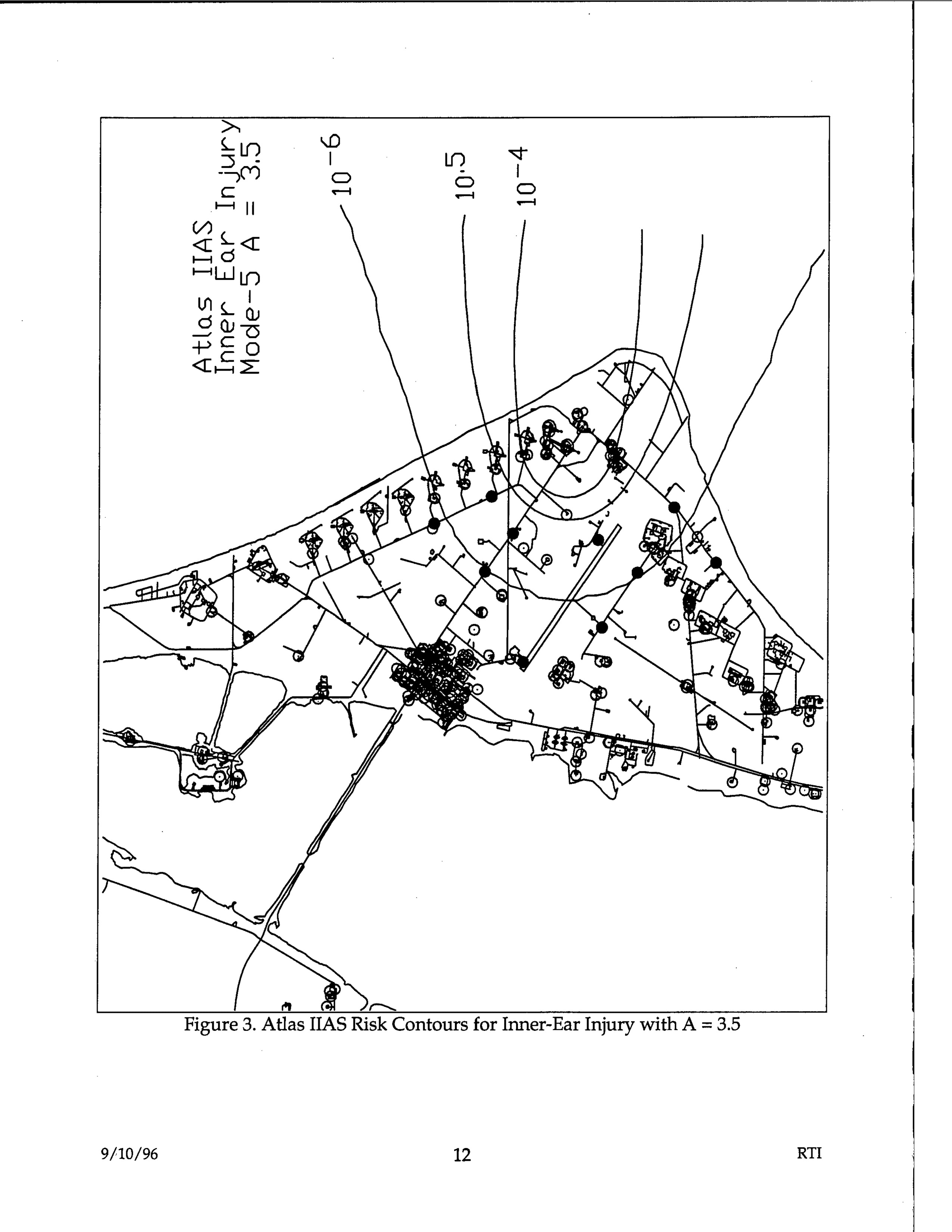
Figure 3. Atlas IIAS Risk Contours for Inner-Ear Injury with A = 3.5
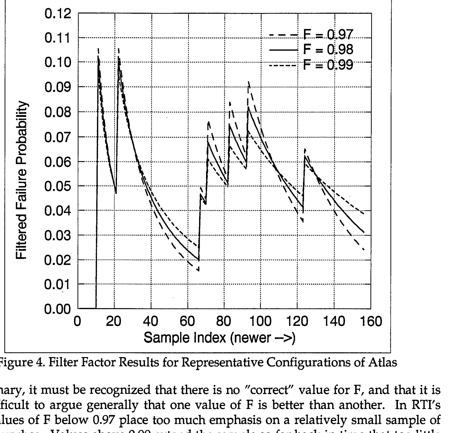
Filter Factor Results for Representative Configurations of Atlas
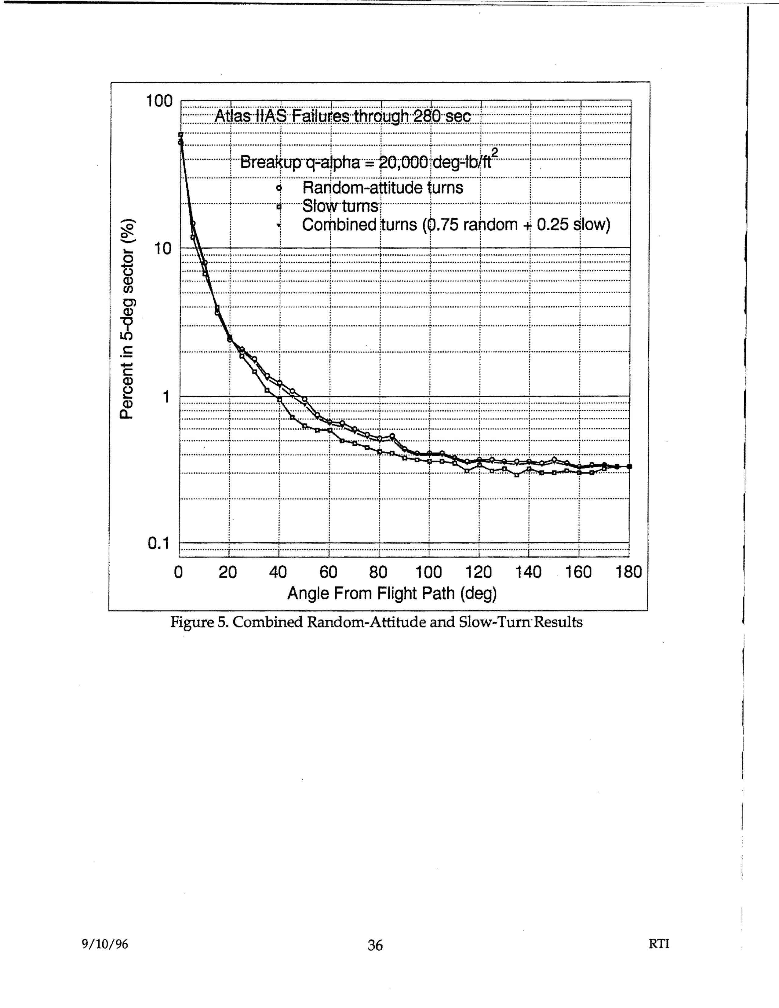
Atlas IIAS Failures through 280 sec - Breakup q-alpha = 20,000 deg-lb/ft² - Random-attitude turns, Slow turns, Combined turns (0.75 random + 0.25 slow) - Percent in 5-deg sector vs Angle From Flight Path (deg)
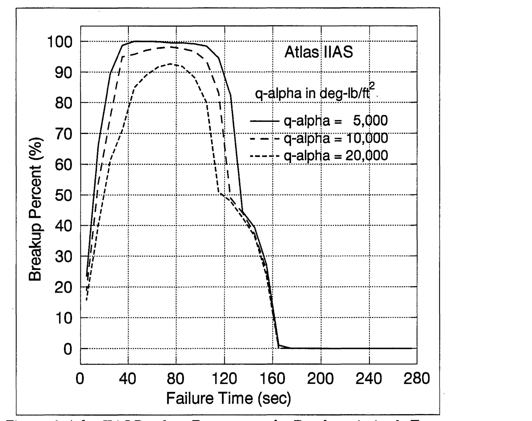
Figure 6. Atlas IIAS Breakup Percentages for Random-Attitude Turns
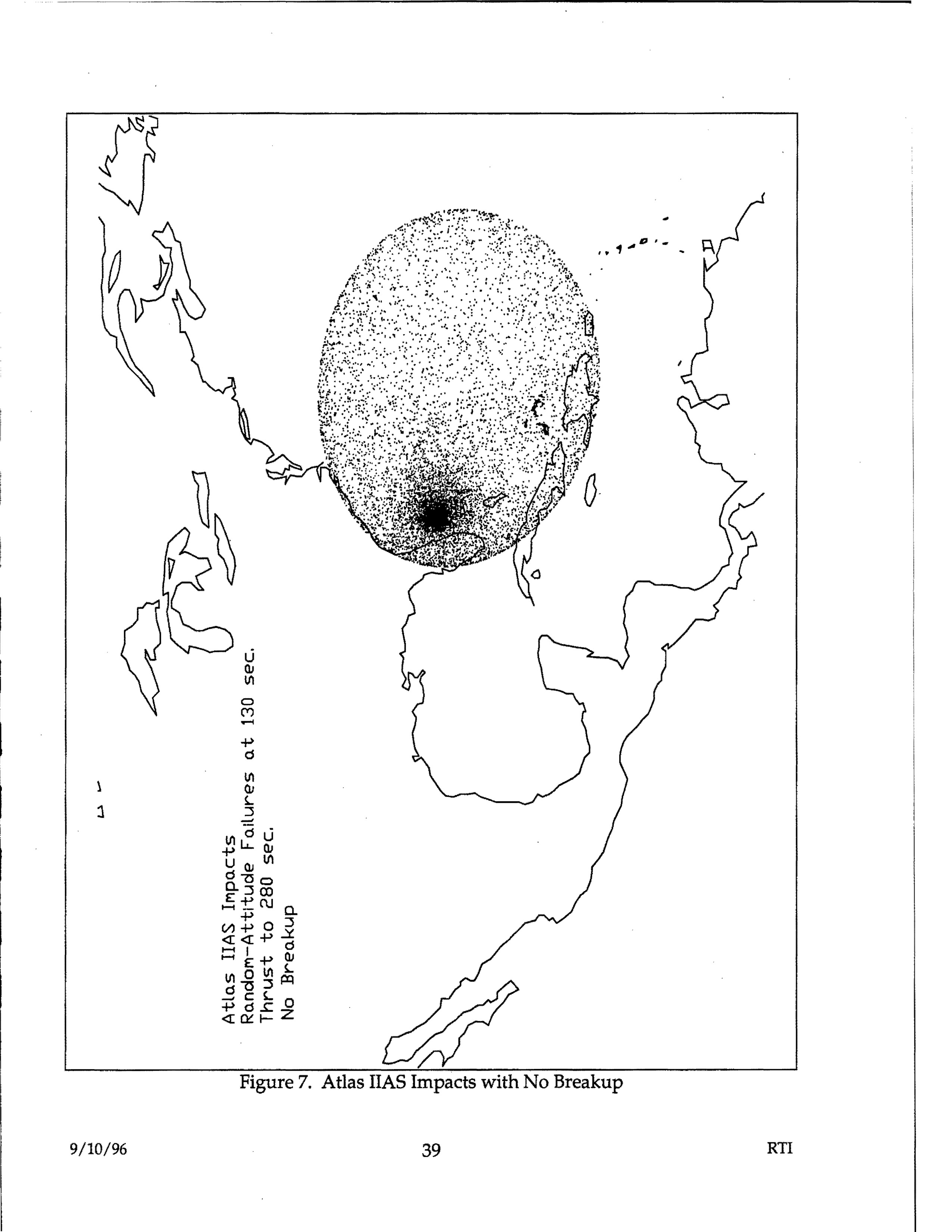
Atlas IIAS Impacts with No Breakup - map showing random-attitude failures at t30 sec thrust to 280 sec with impact footprint overlay
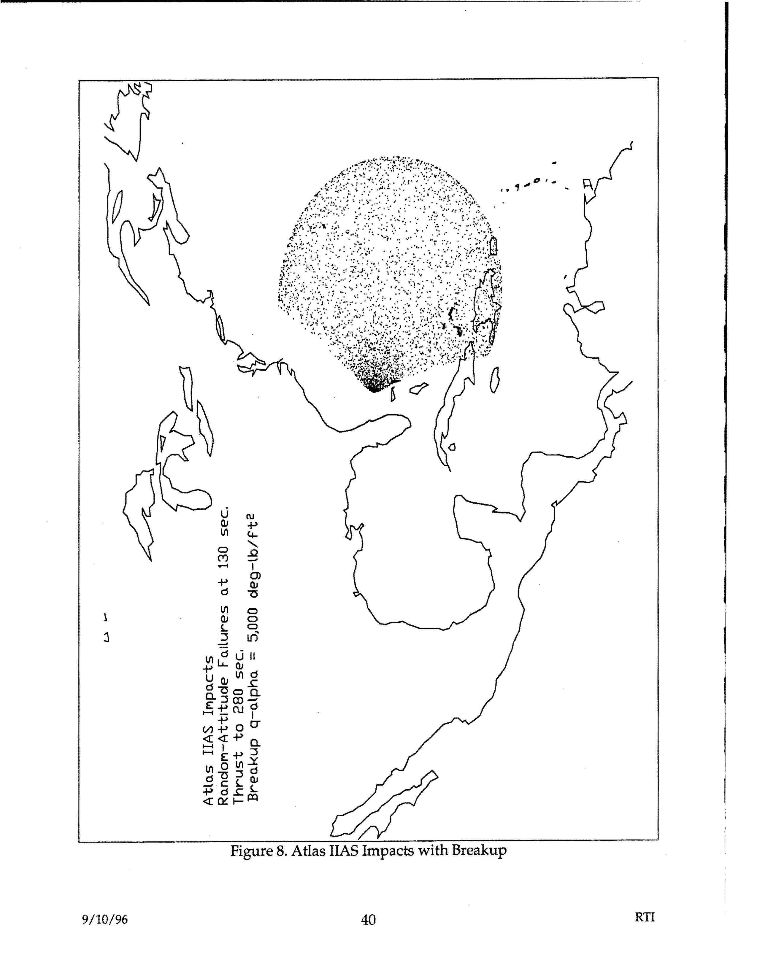
Atlas IIAS Impacts with Breakup - Random-Attitude Failures at 130 sec, Thrust to 230 sec, Breakup q-alpha = 5000 deg-lb/ft²
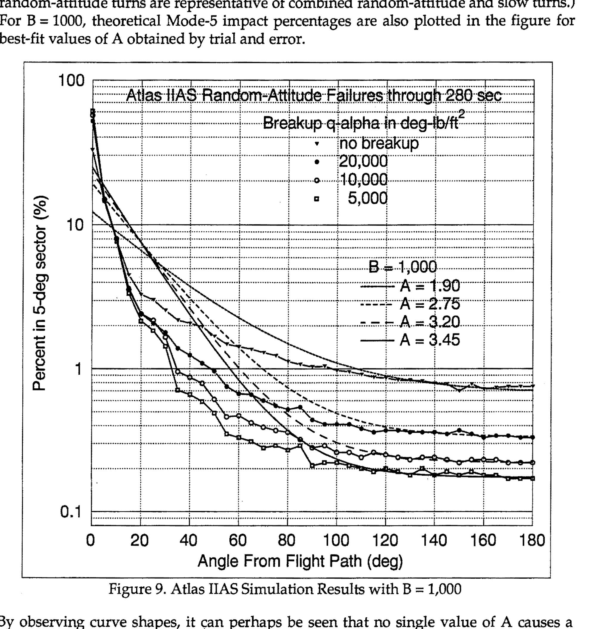
Figure 9. Atlas IIAS Simulation Results with B = 1,000
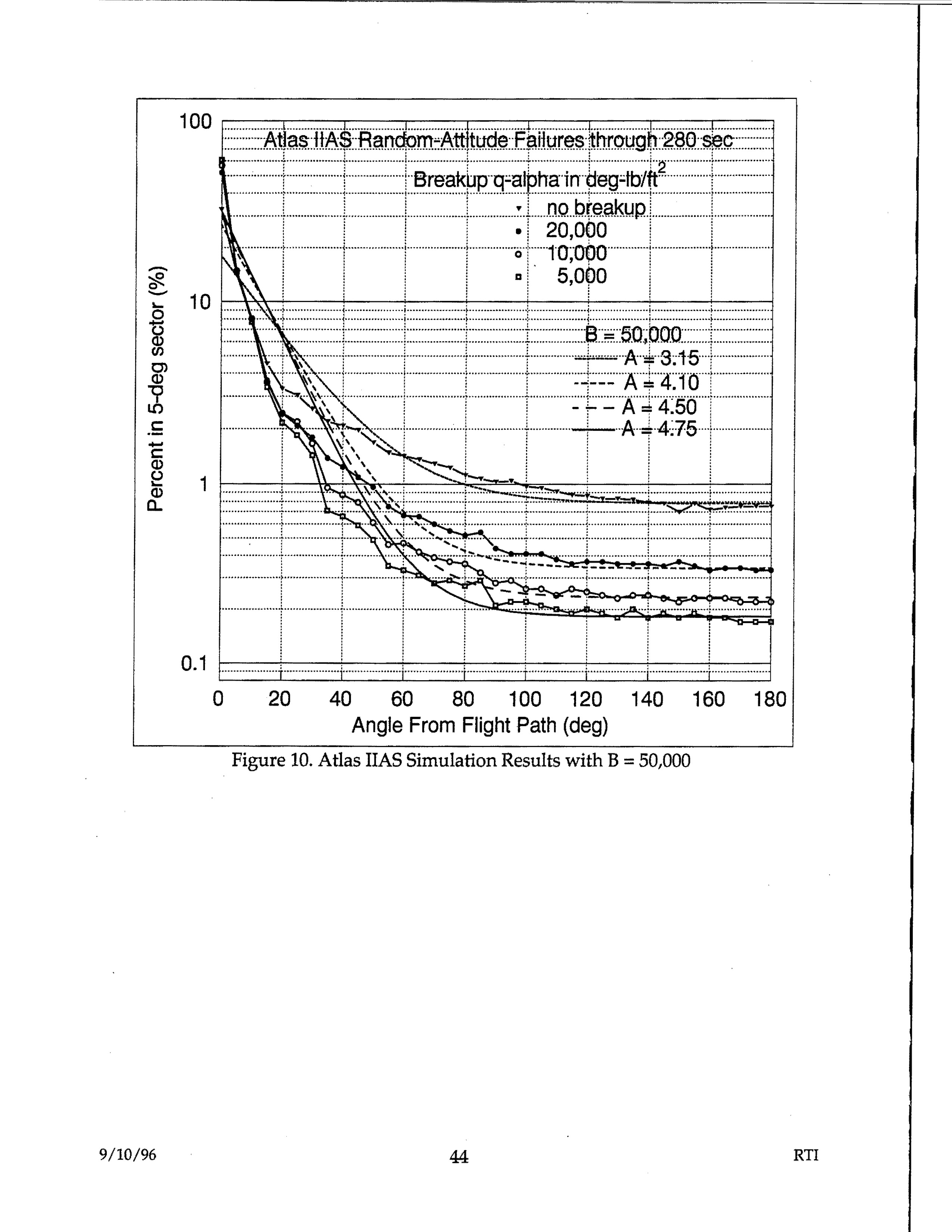
Figure 10. Atlas IIAS Simulation Results with B = 50,000 - Graph showing Percent in 5-deg sector (%) vs Angle From Flight Path (deg), with multiple curves for different Breakup q-alpha values in deg-lb/ft
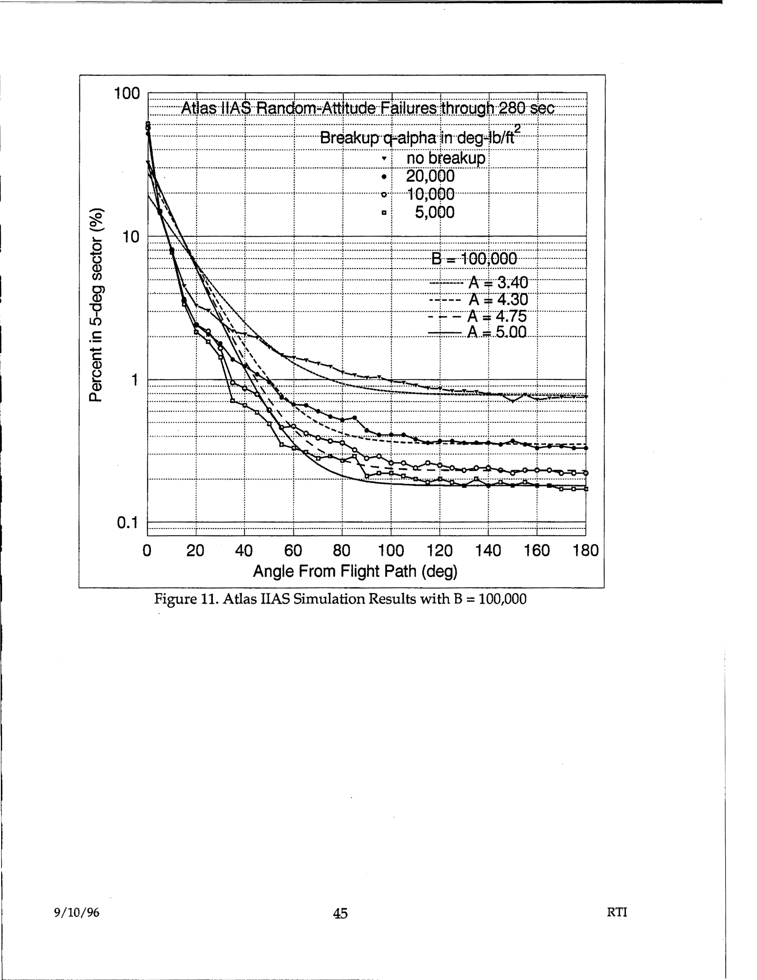
Figure 11. Atlas IIAS Simulation Results with B = 100,000 - Graph showing Atlas IIAS Random-Attitude Failures through 280 sec, plotting Percent in 5-deg sector vs Angle From Flight Path (deg), with multiple curves for different Breakup q-alpha values in deg-lb/ft² (no breakup, 20,000, 10,000, 5,000) and B = 100,000 with A values of 3.40, 4.30, 4.75, and 5.00
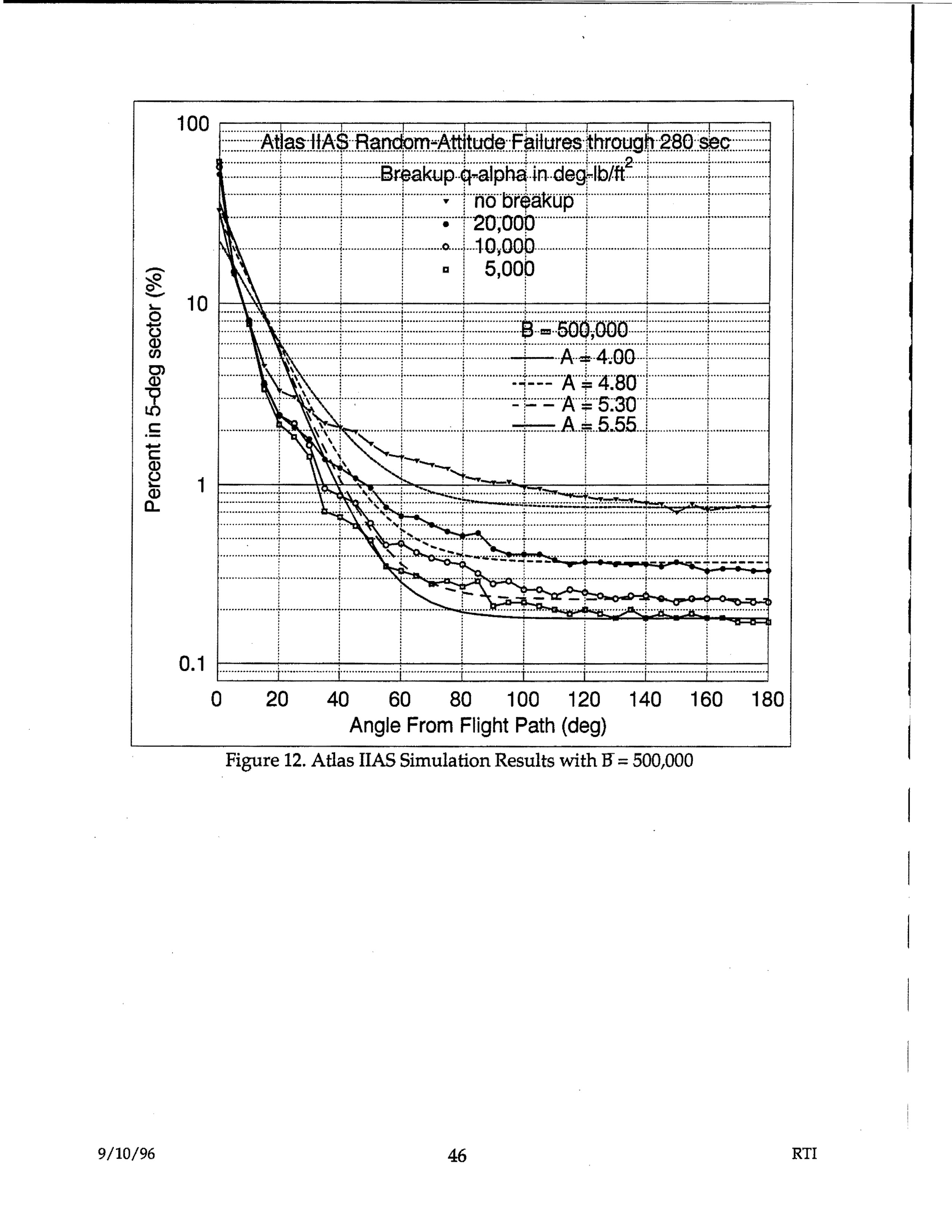
Atlas IIAS Random-Attitude Failures through 280 sec - Breakup q-alpha in deg-lb/ft - showing percent in 5-deg sector vs angle from flight path with various breakup values (no breakup, 20,000, 10,000, 5,000) and B=500,000 with A values 4.00, 4.80, 5.30, 5.55
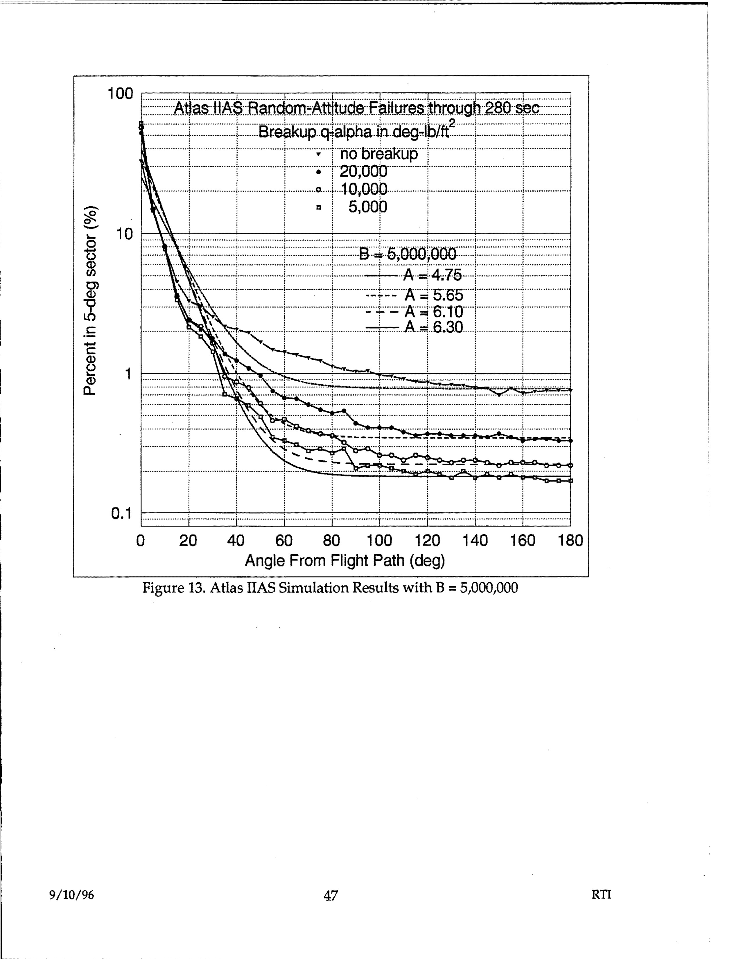
Atlas IIAS Random-Attitude Failures through 280 sec, Breakup q-alpha in deg-lb/ft^2, showing percent in 5-deg sector vs angle from flight path
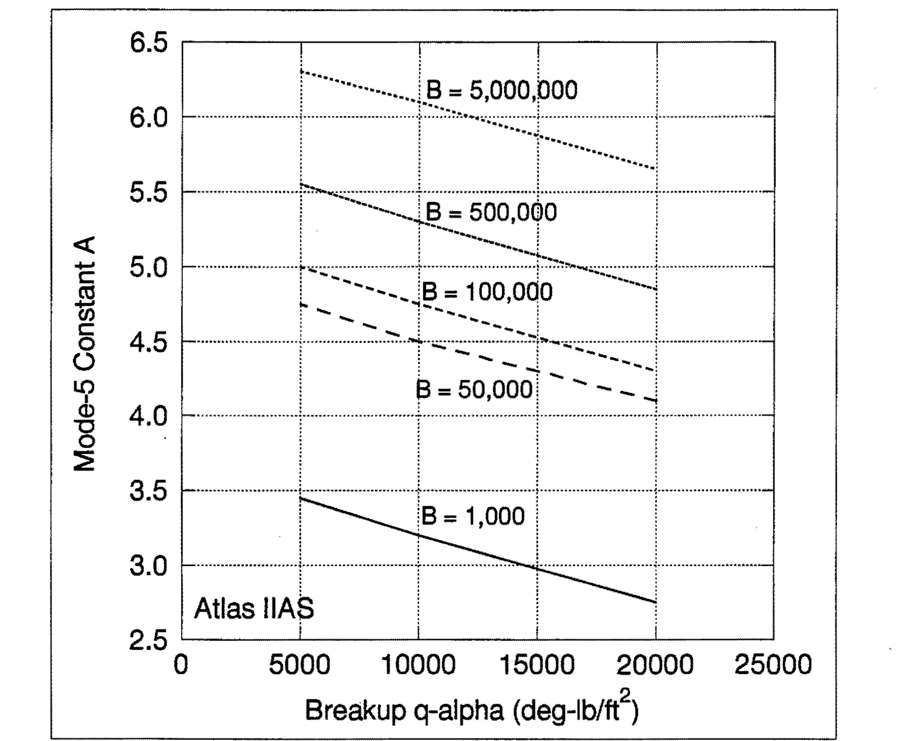
Figure 14. Effects of Breakup q-alpha on A for Atlas IIAS
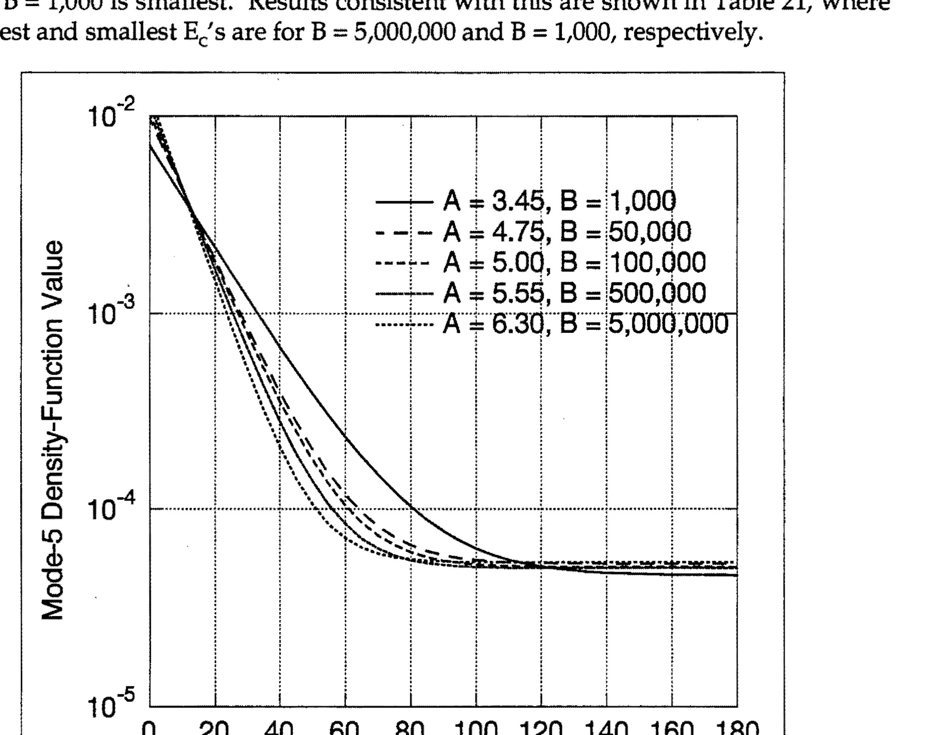
Figure 15. Mode-5 Density-Function Values at Three Miles
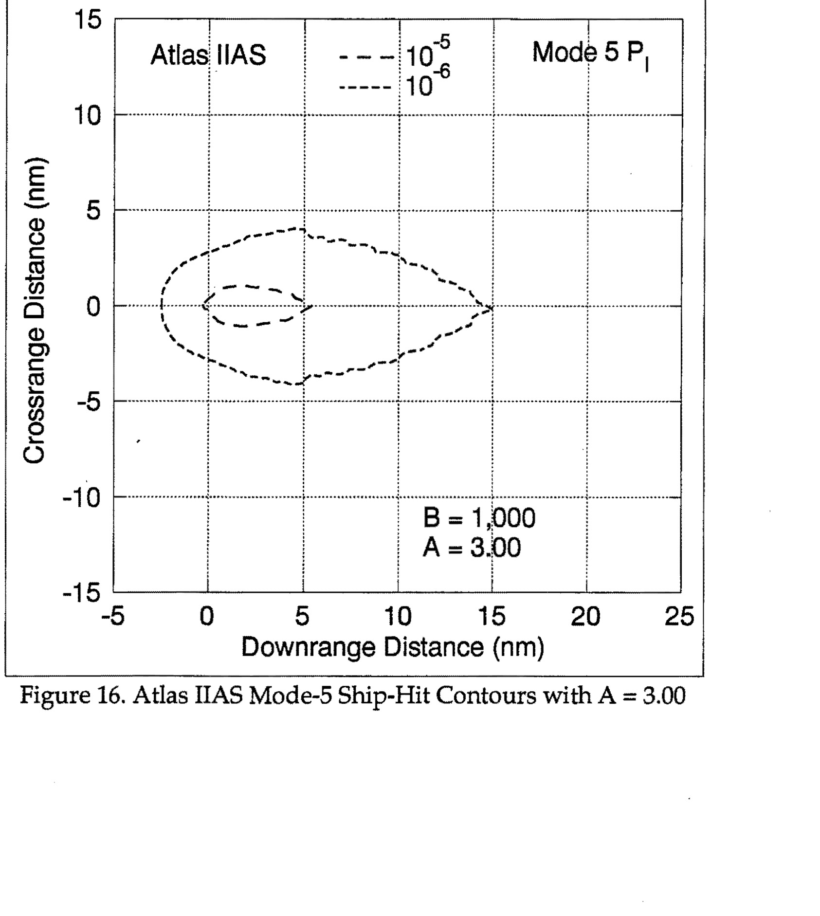
Atlas IIAS Mode-5 Ship-Hit Contours with A = 3.00, showing crossrange distance vs downrange distance with contour lines for 10^-5 and 10^-6, B = 1,000 and A = 3.00
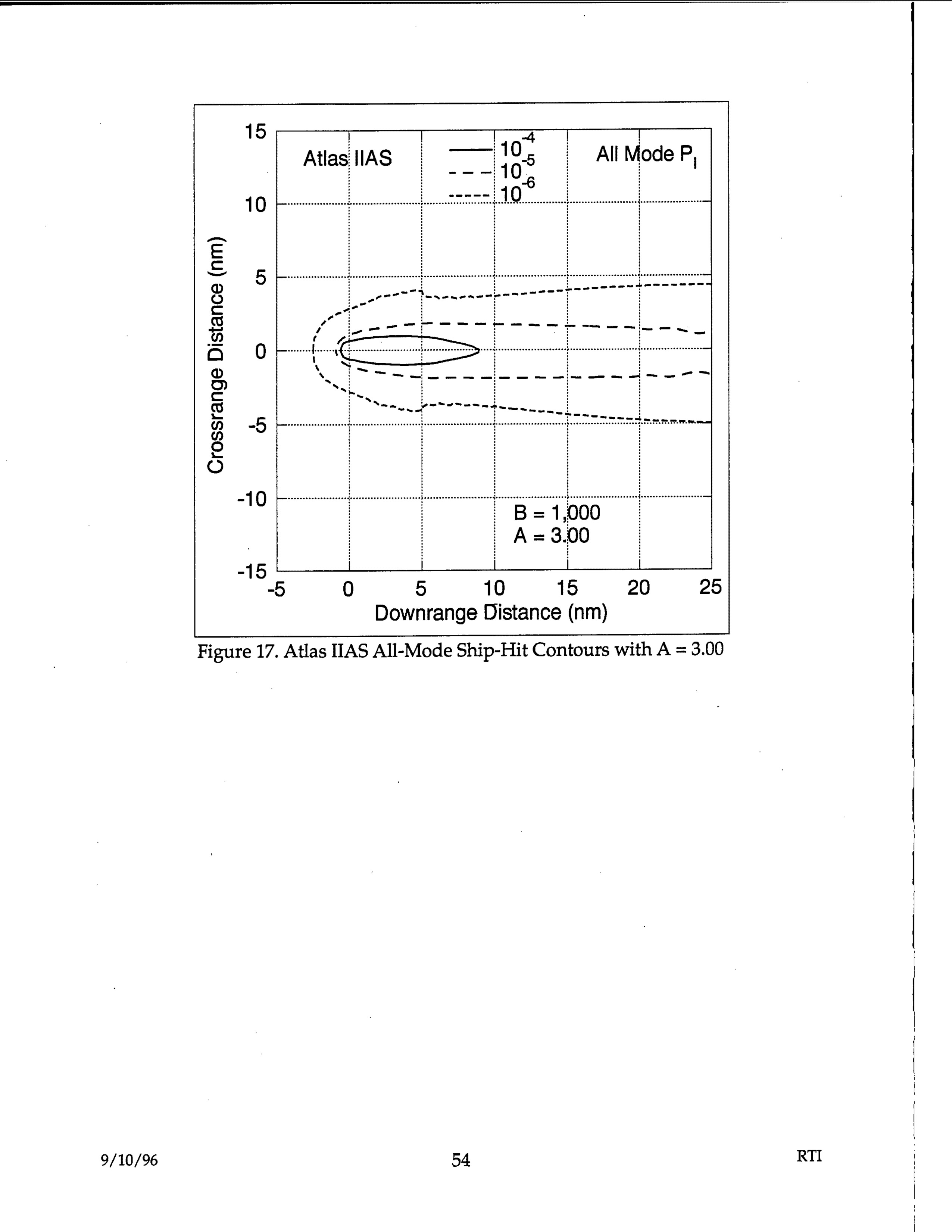
Atlas IIAS All-Mode Ship-Hit Contours showing crossrange distance (nm) vs downrange distance (nm) with probability contours 10^-4, 10^-5, 10^-6, B = 1,000, A = 3.00
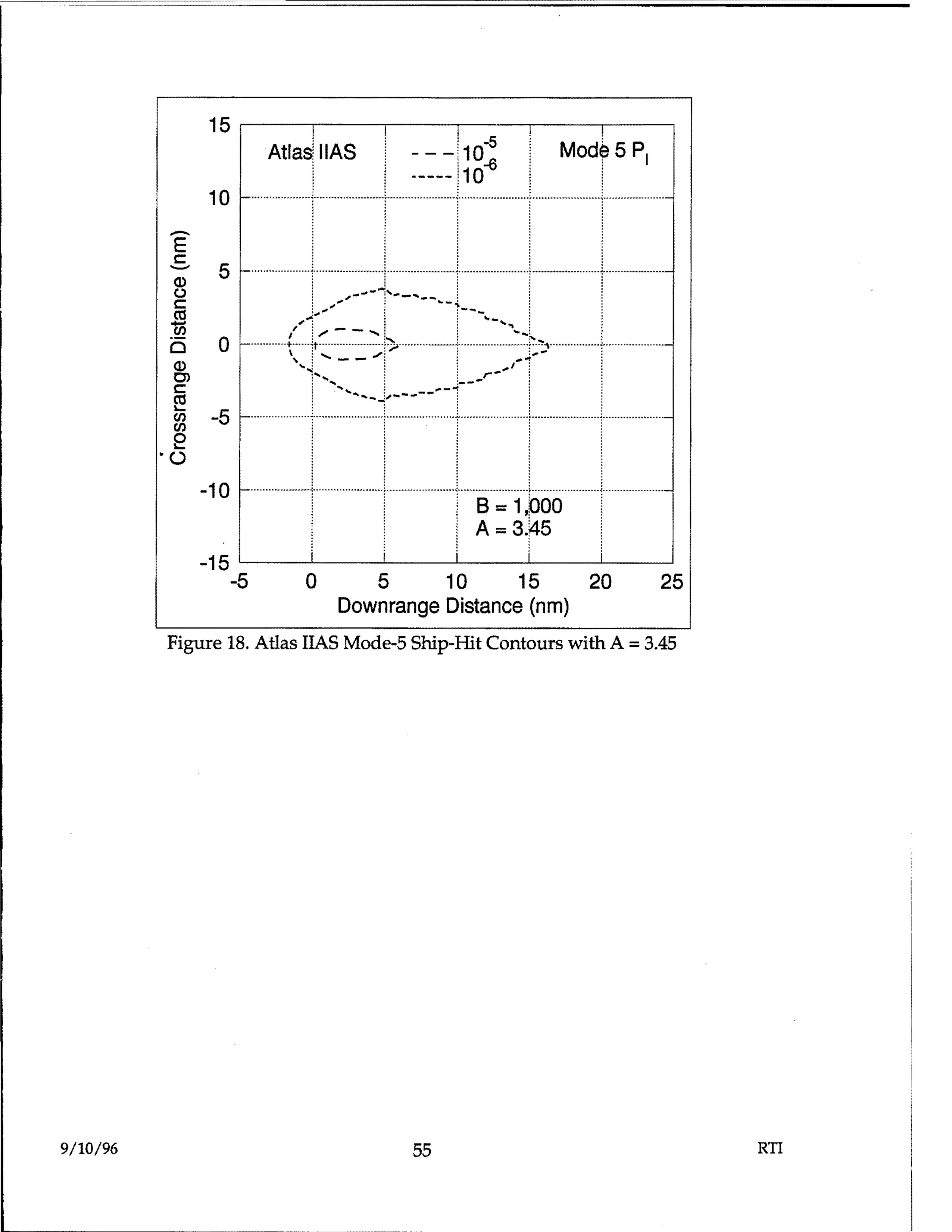
Atlas IIAS Mode-5 Ship-Hit Contours showing crossrange vs downrange distance with probability contours 10^-5 and 10^-8, Mode 5 P_I, B=1,000, A=3.45
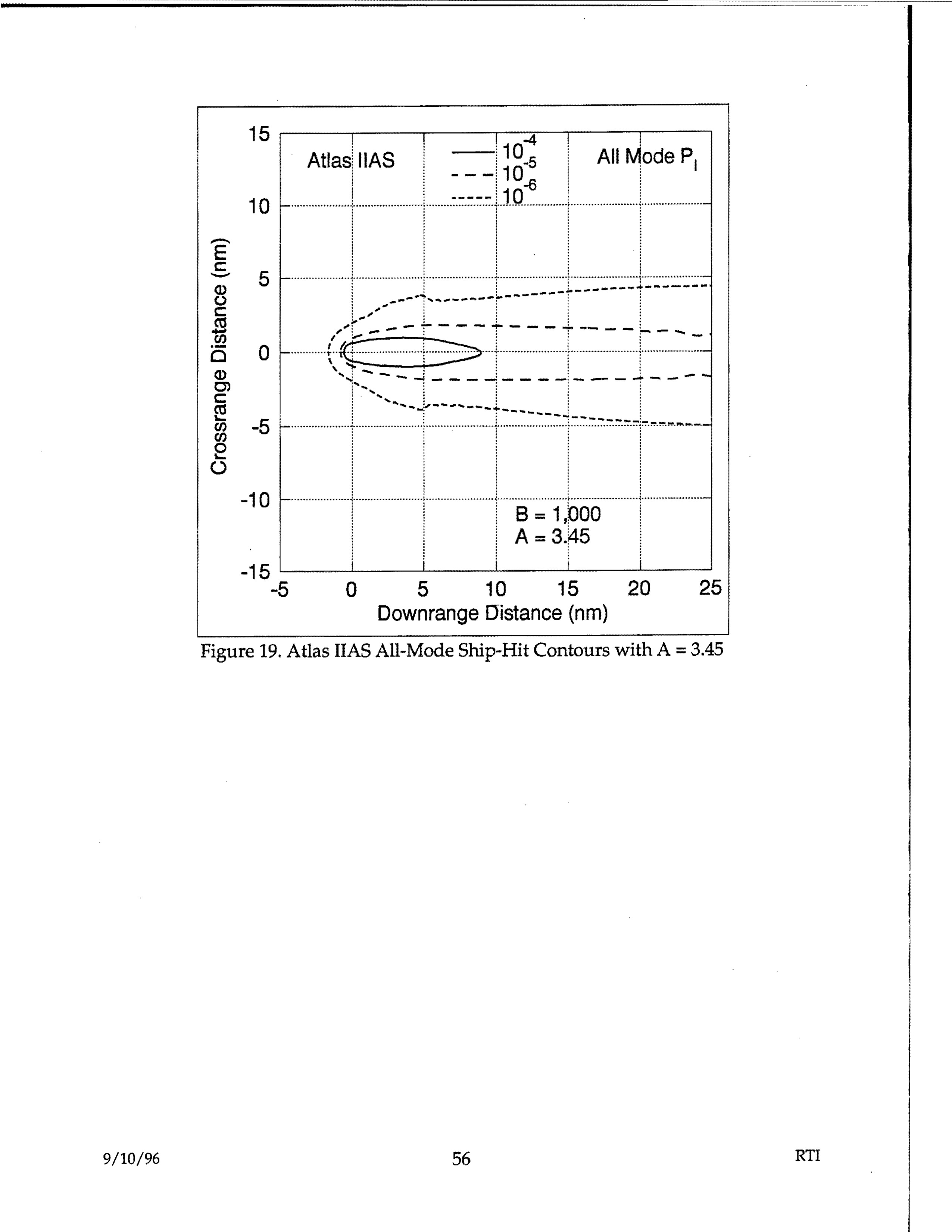
Atlas IIAS All-Mode Ship-Hit Contours with A = 3.45, showing crossrange distance (nm) vs downrange distance (nm) with probability contours 10^-4, 10^-5, 10^-6 and parameters B = 1,000, A = 3.45
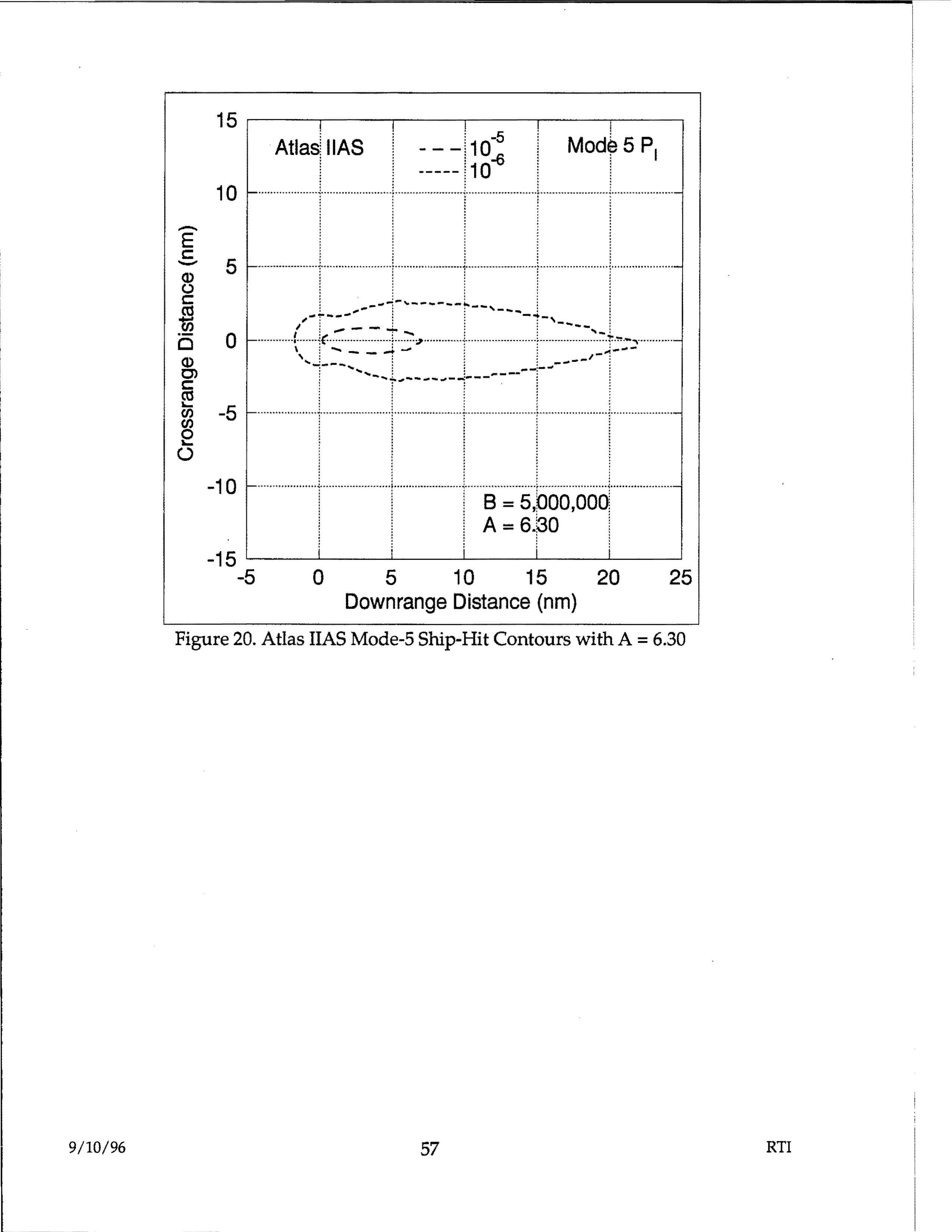
Atlas IIAS Mode-5 Ship-Hit Contours showing crossrange distance vs downrange distance with probability contours 10^-5 and 10^-6, B = 5,000,000, A = 6.30
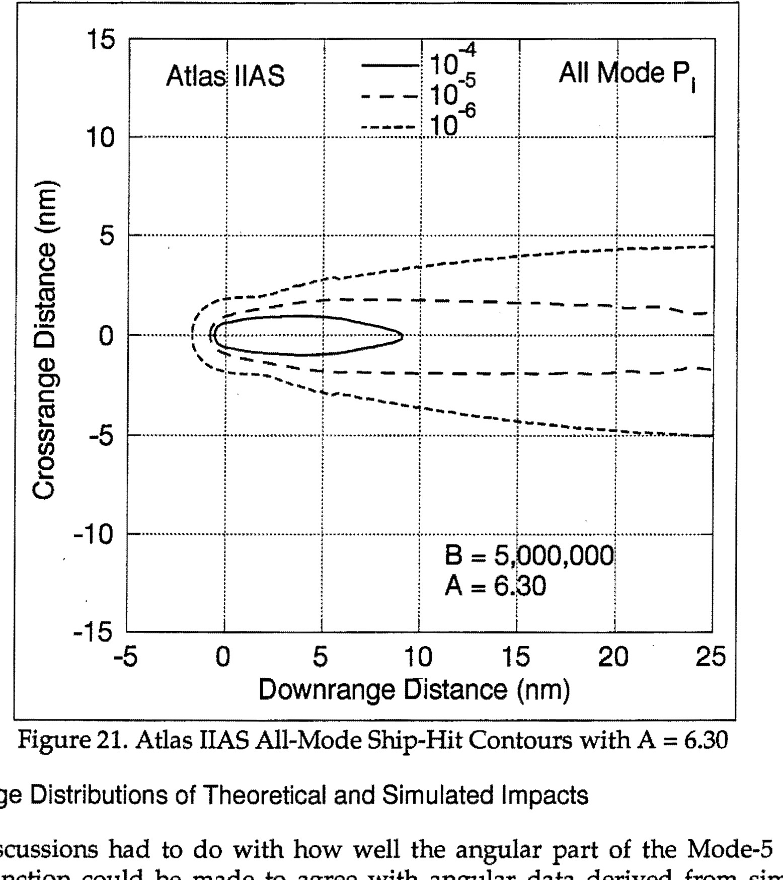
Figure 21. Atlas IIAS All-Mode Ship-Hit Contours with A = 6.30
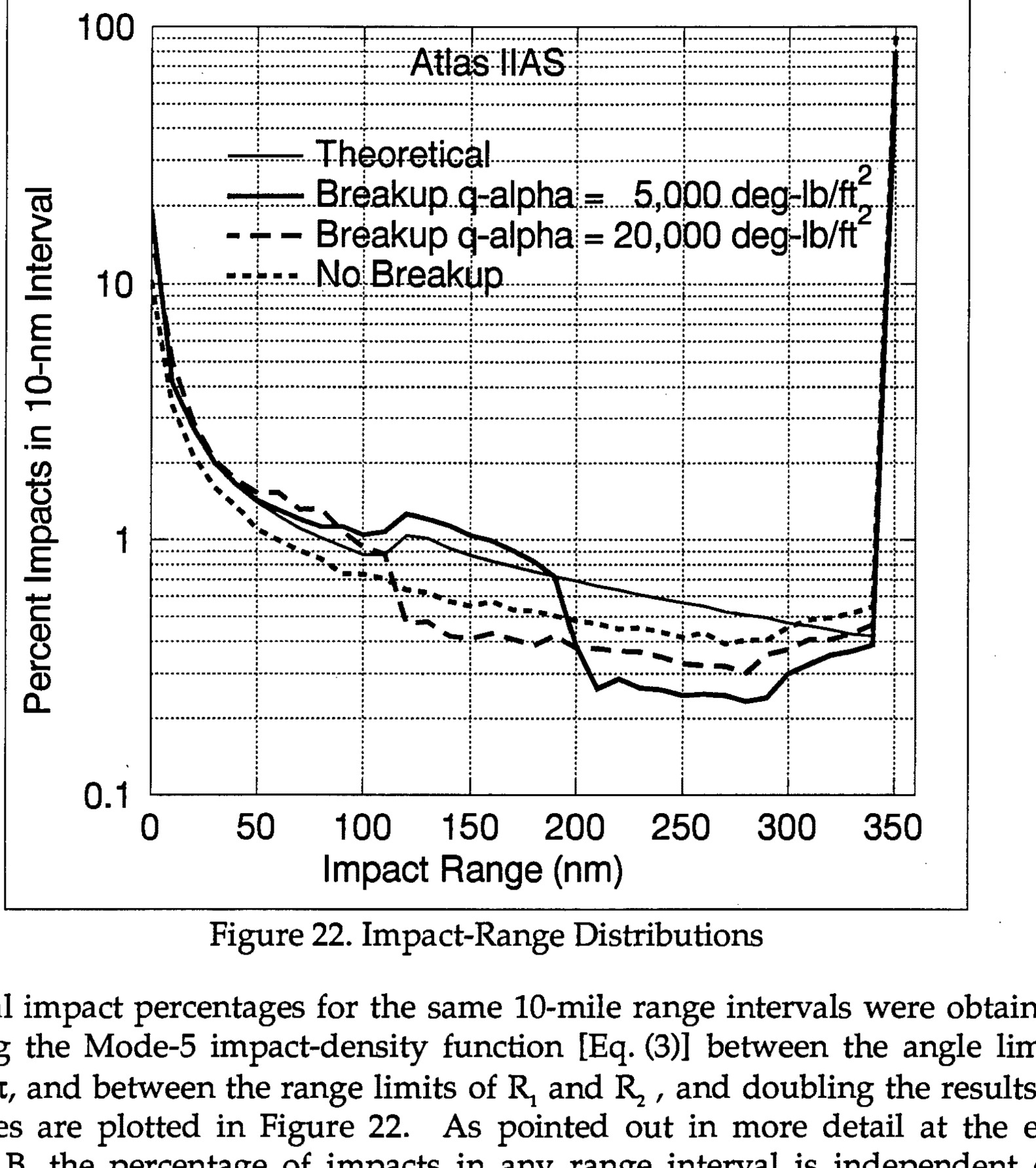
Figure 22. Impact-Range Distributions - Graph showing percent impacts in 10-nm interval vs impact range (nm) with Atlas IIAS theoretical and breakup q-alpha curves
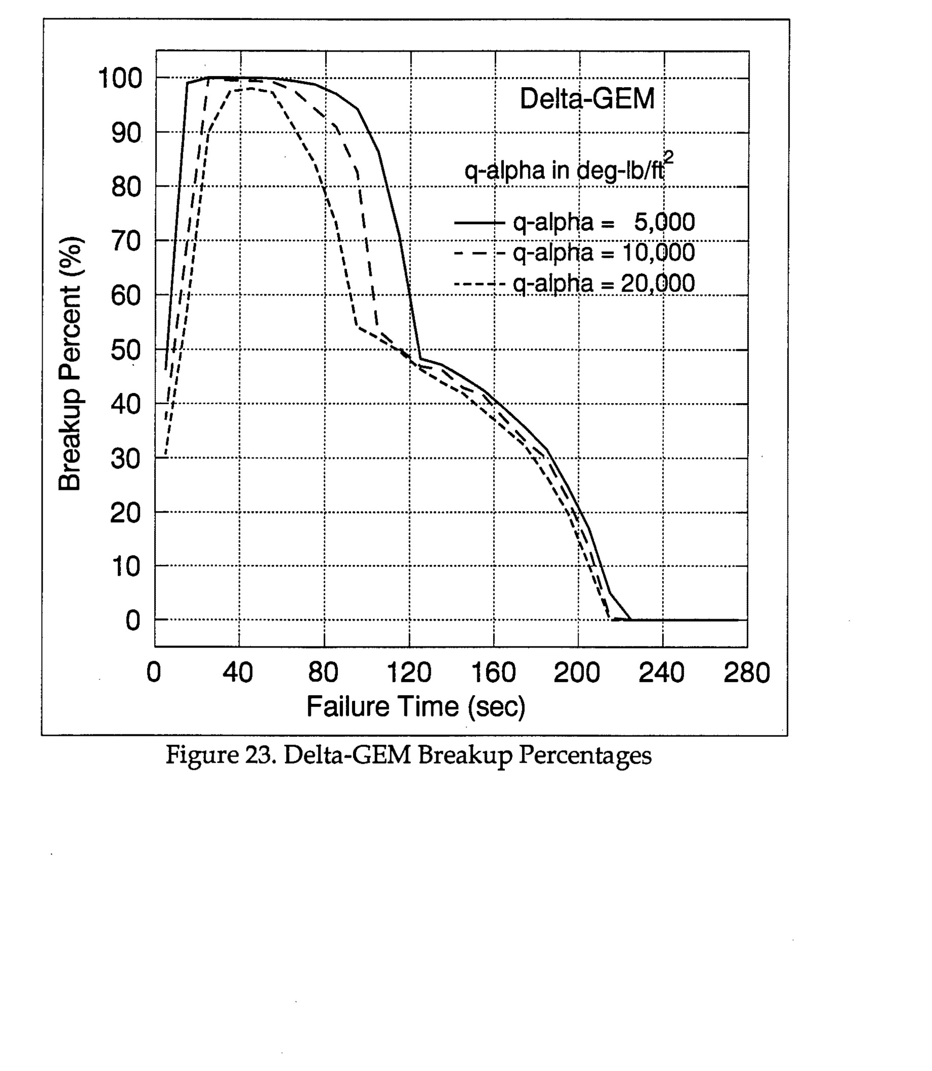
Figure 23. Delta-GEM Breakup Percentages - Graph showing breakup percent vs failure time for three q-alpha values (5,000, 10,000, and 20,000 deg-lb/ft²)
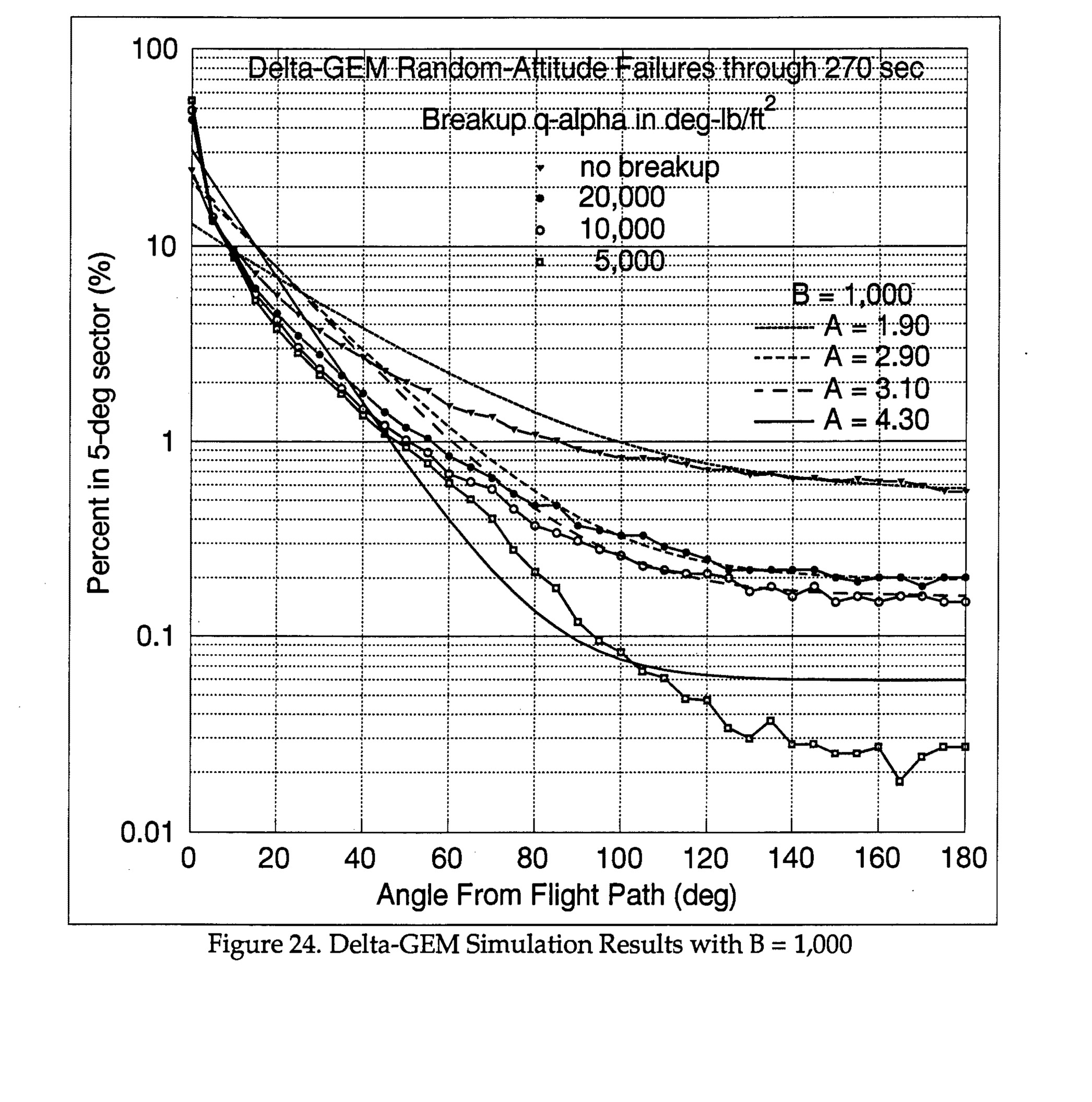
Delta-GEM Random-Altitude Failures through 270 sec, showing Percent in 5-deg sector vs Angle From Flight Path, with breakup q-alpha values and theoretical Mode-5 curves for various A values with B=1,000
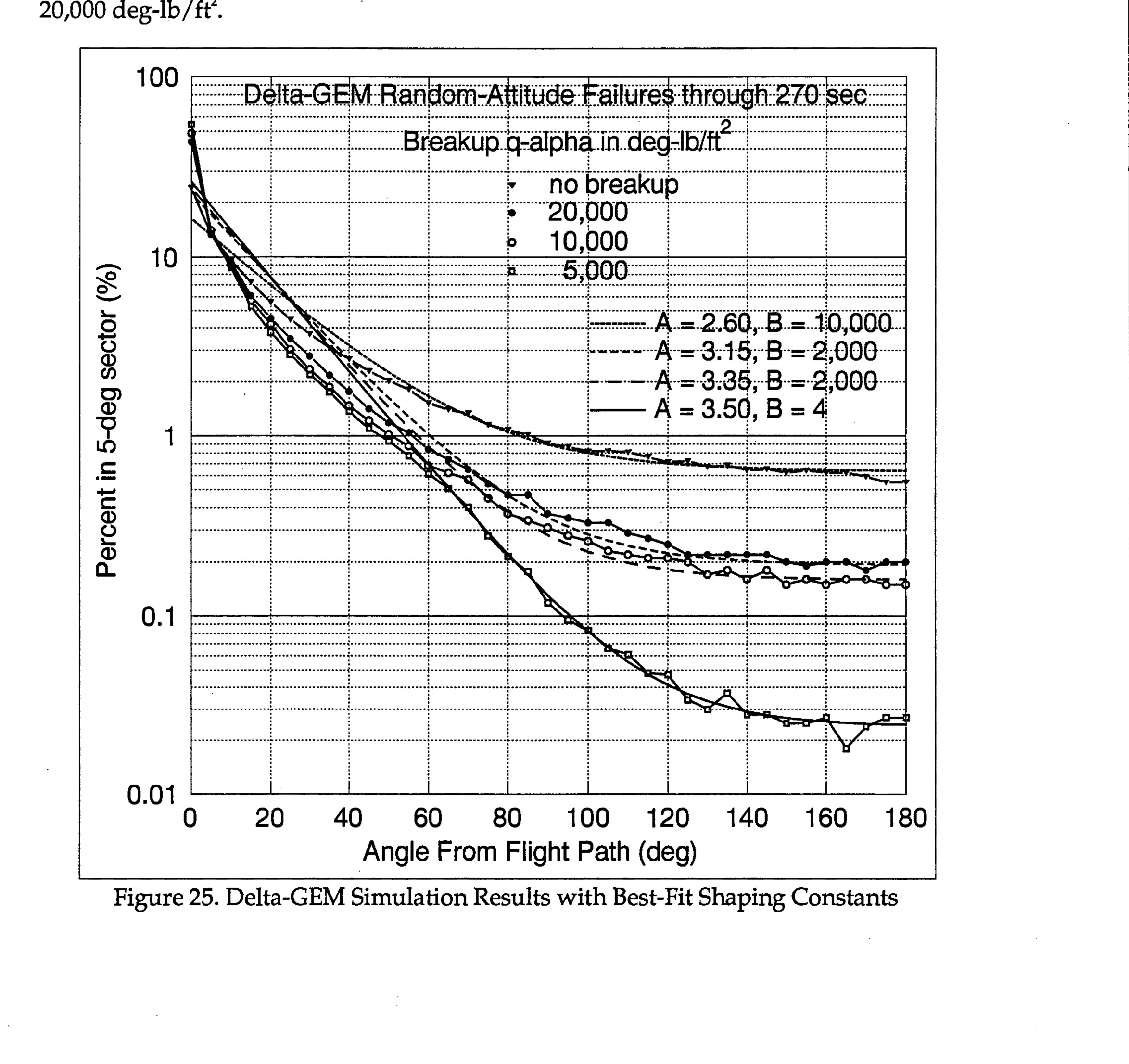
Delta-GEM Simulation Results with Best-Fit Shaping Constants showing percent in 5-deg sector vs angle from flight path for various breakup q-alpha values
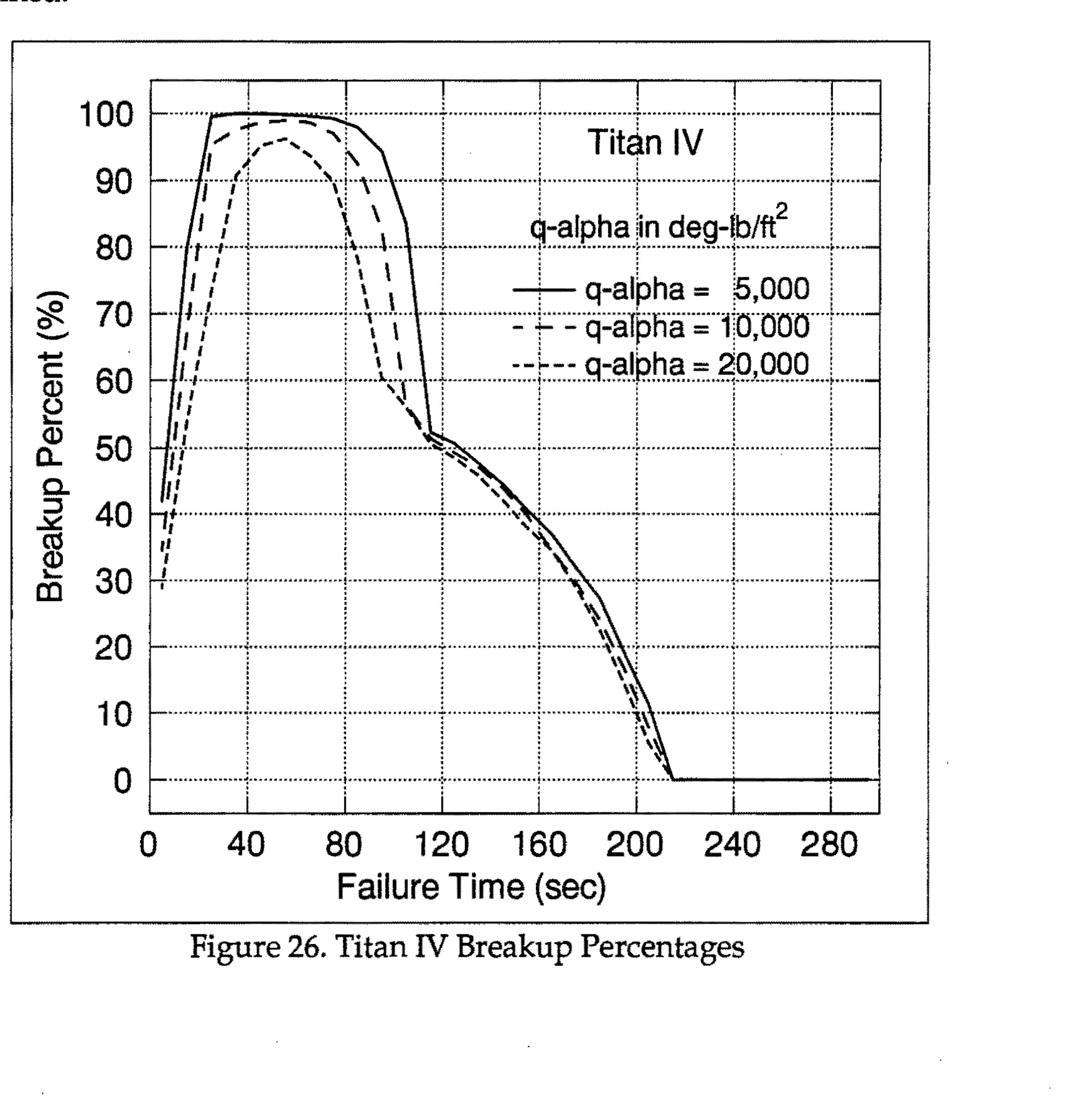
Figure 26. Titan IV Breakup Percentages - Graph showing Breakup Percent (%) vs Failure Time (sec) for three q-alpha values: 5,000, 10,000, and 20,000 deg-lb/ft²
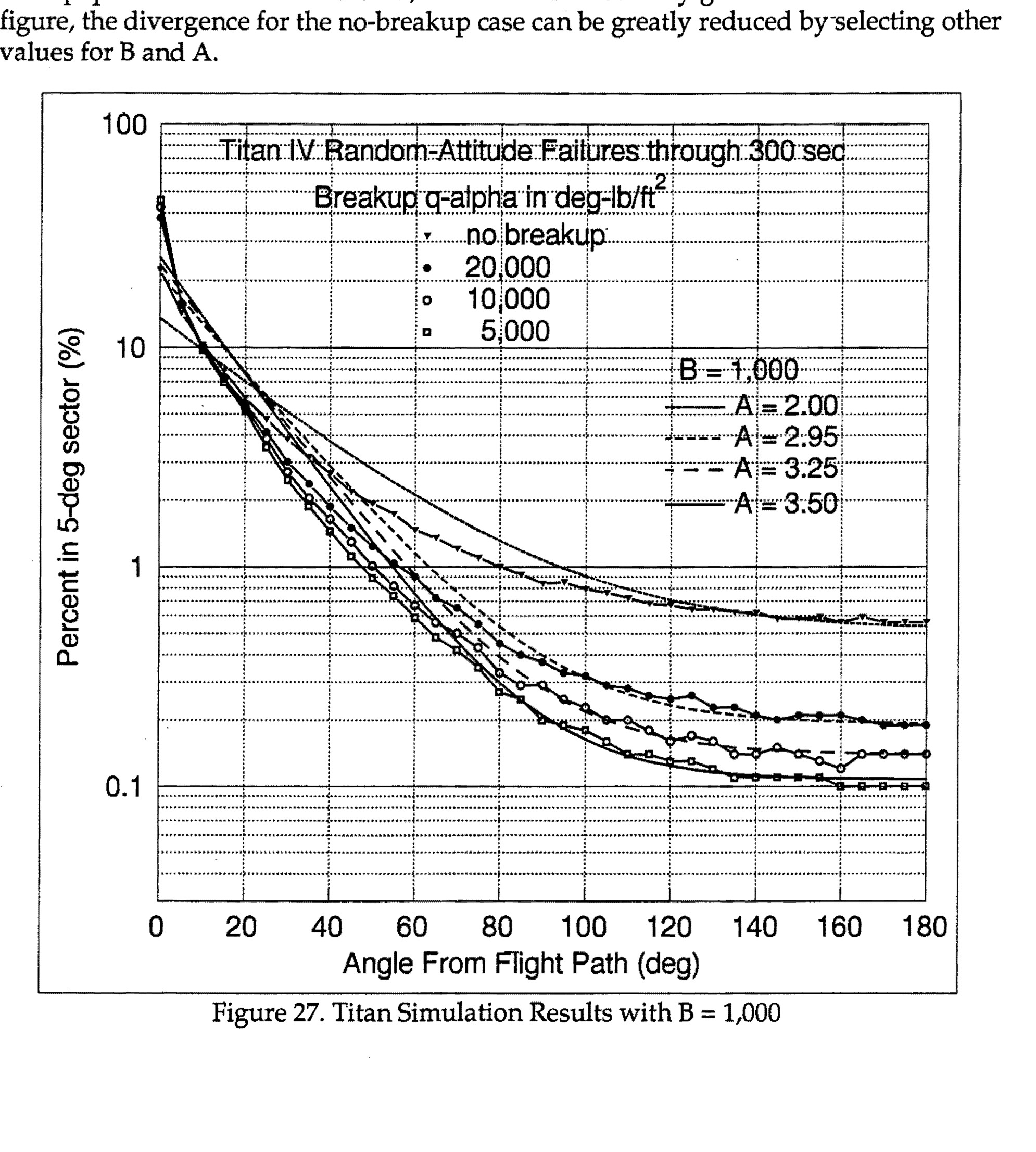
Figure 27. Titan Simulation Results with B = 1,000 - Graph showing Percent in 5-deg sector vs Angle From Flight Path (deg) with multiple curves for different breakup q-alpha values and no breakup scenarios
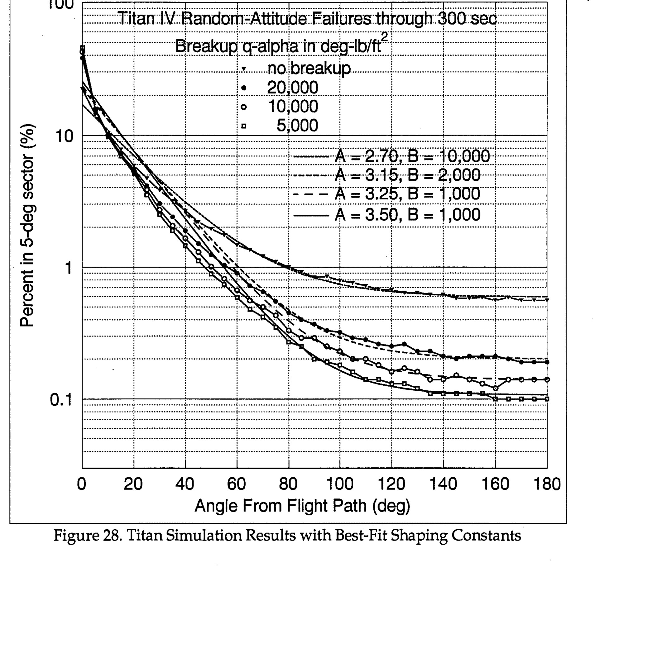
Titan IV Random-Attitude Failures through 300 sec, showing Breakup α-alpha in deg-lb/ft² with various parameters (no breakup, 20,000, 10,000, 5,000) and curves for A=2.70, B=10,000; A=3.15, B=2,000; A=3.25, B=1,000; A=3.50, B=1,000. Y-axis: Percent in 5-deg sector (%), logarithmic scale 0.1 to 100. X-axis: Angle From Flight Path (deg), 0 to 180.
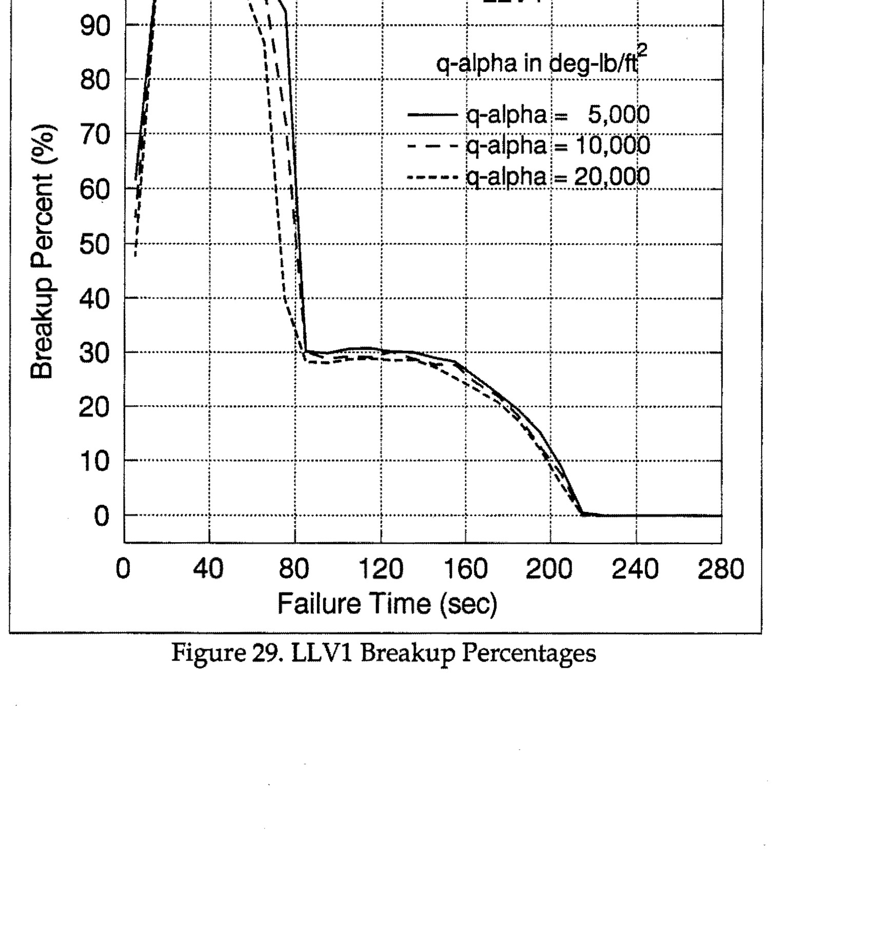
Figure 29. LLV1 Breakup Percentages - Graph showing breakup percent vs failure time with three curves for q-alpha values of 5,000, 10,000, and 20,000 deg-lb/ft²
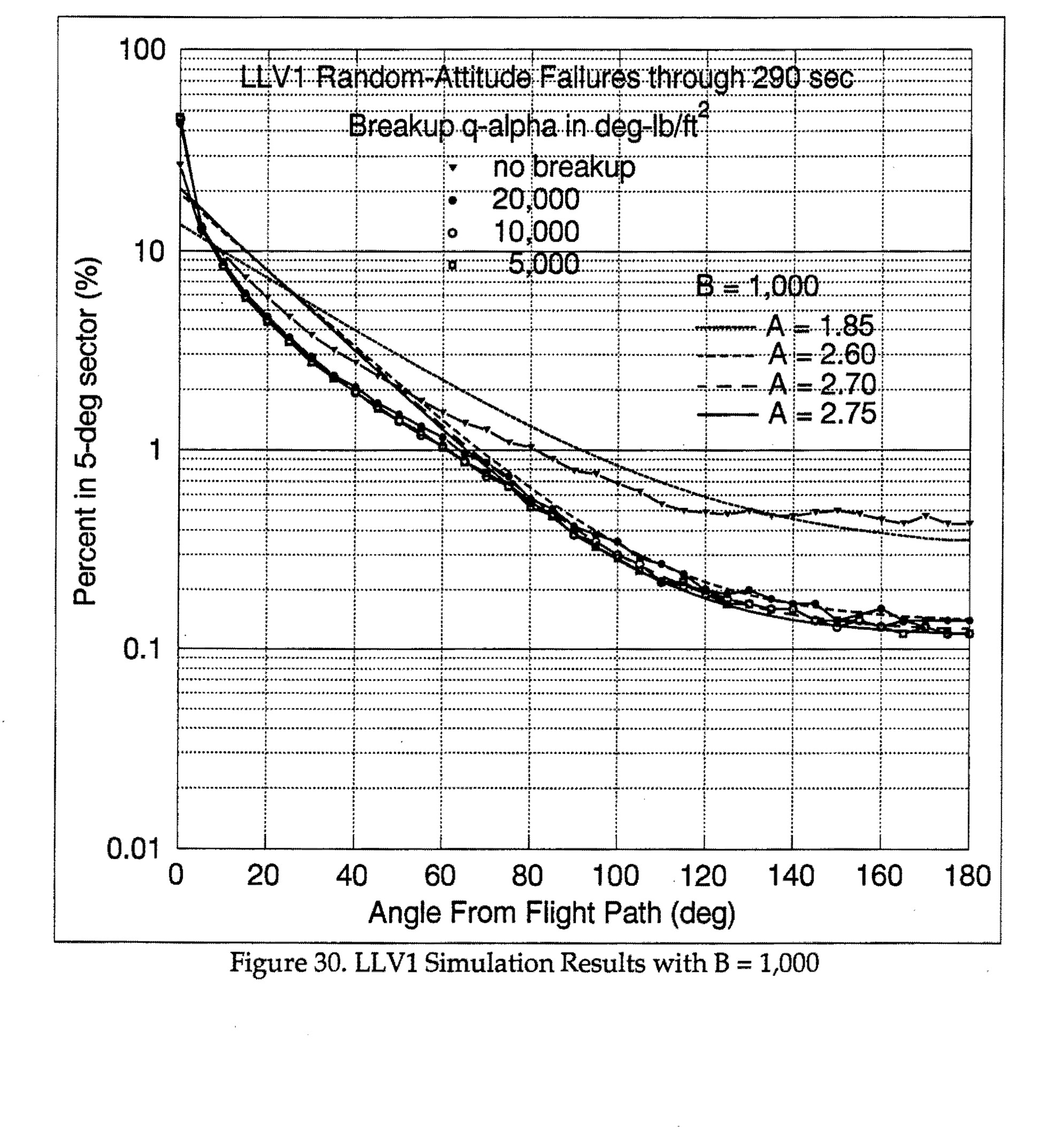
Figure 30. LLV1 Simulation Results with B = 1,000 - Graph showing percent in 5-deg sector vs angle from flight path, with multiple curves for different breakup q-alpha values and A values
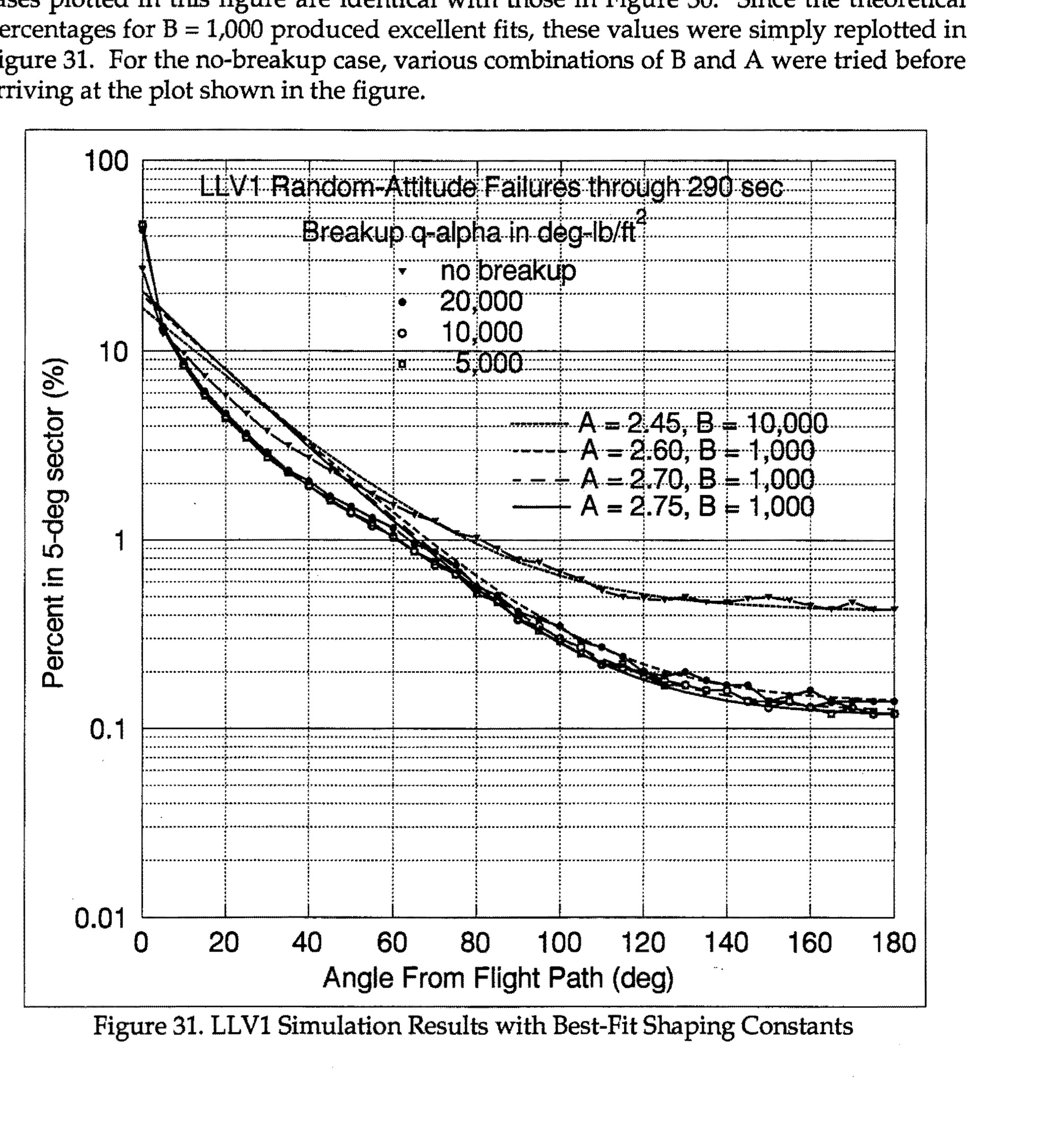
LLV1 Simulation Results with Best-Fit Shaping Constants showing percent in 5-deg sector vs angle from flight path for various breakup q-alpha values and shaping constants
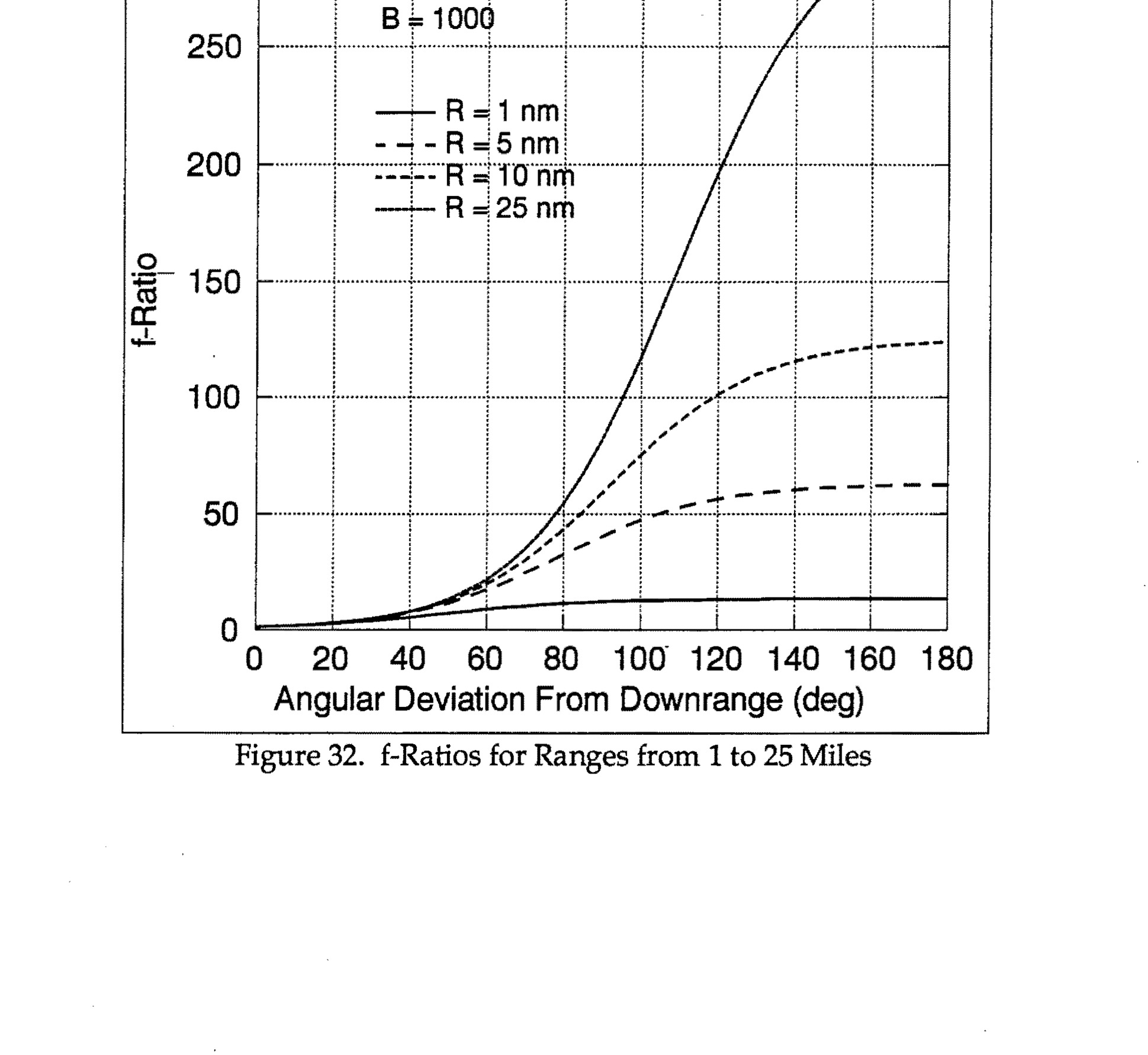
Figure 32. f-Ratios for Ranges from 1 to 25 Miles
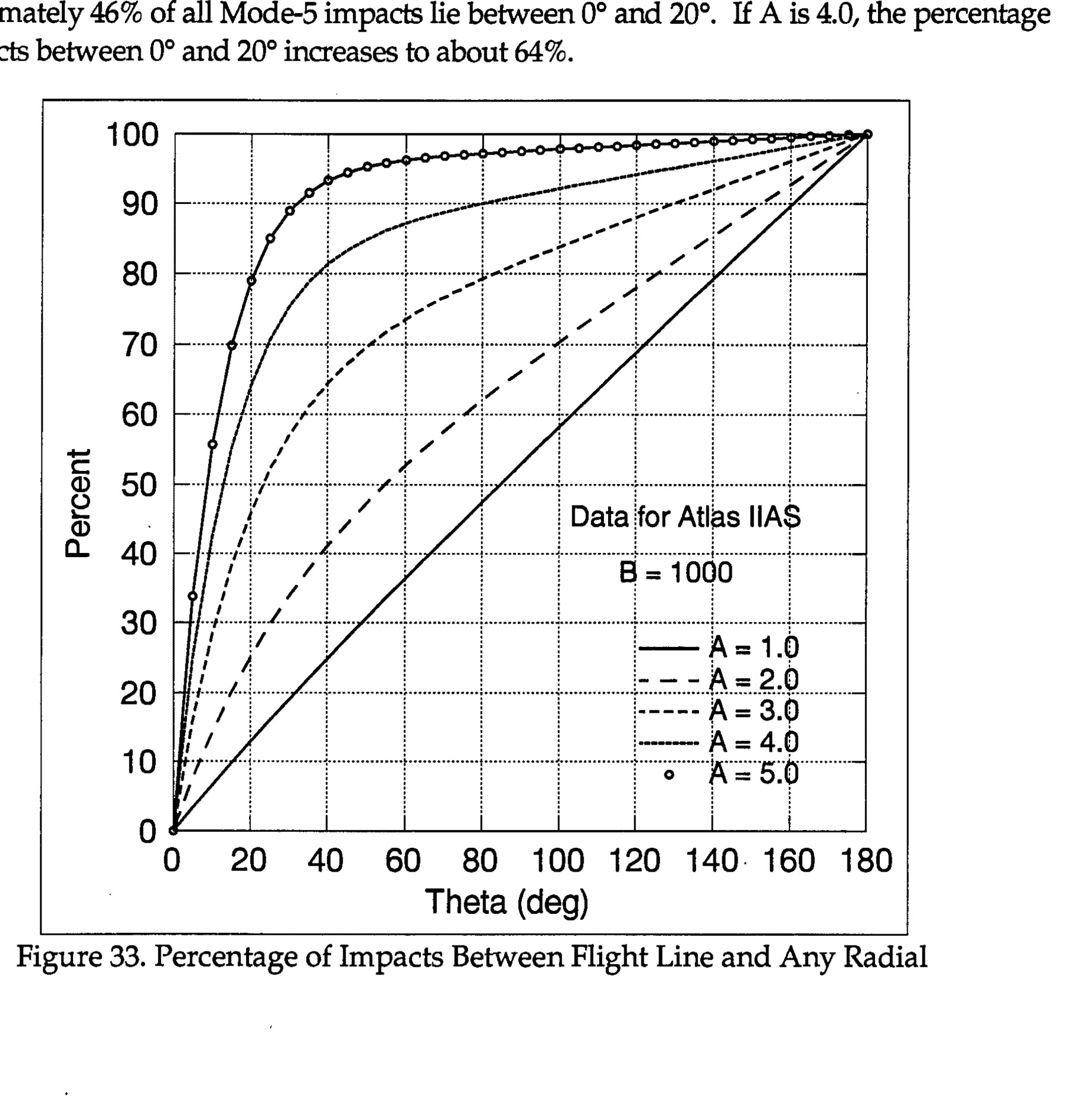
Figure 33. Percentage of Impacts Between Flight Line and Any Radial - Data for Atlas IIAS B = 1000, showing curves for A = 1.0, 2.0, 3.0, 4.0, 5.0
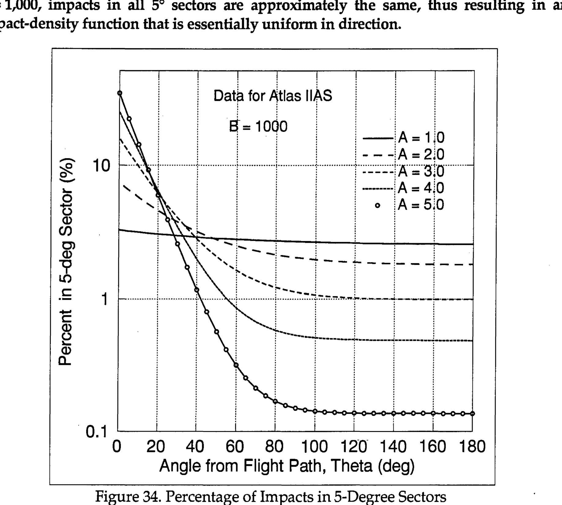
Data for Atlas IIAS, B = 1000, showing Percent in 5-deg Sector vs Angle from Flight Path, Theta (deg) for A values 1.0, 2.0, 3.0, 4.0, 5.0
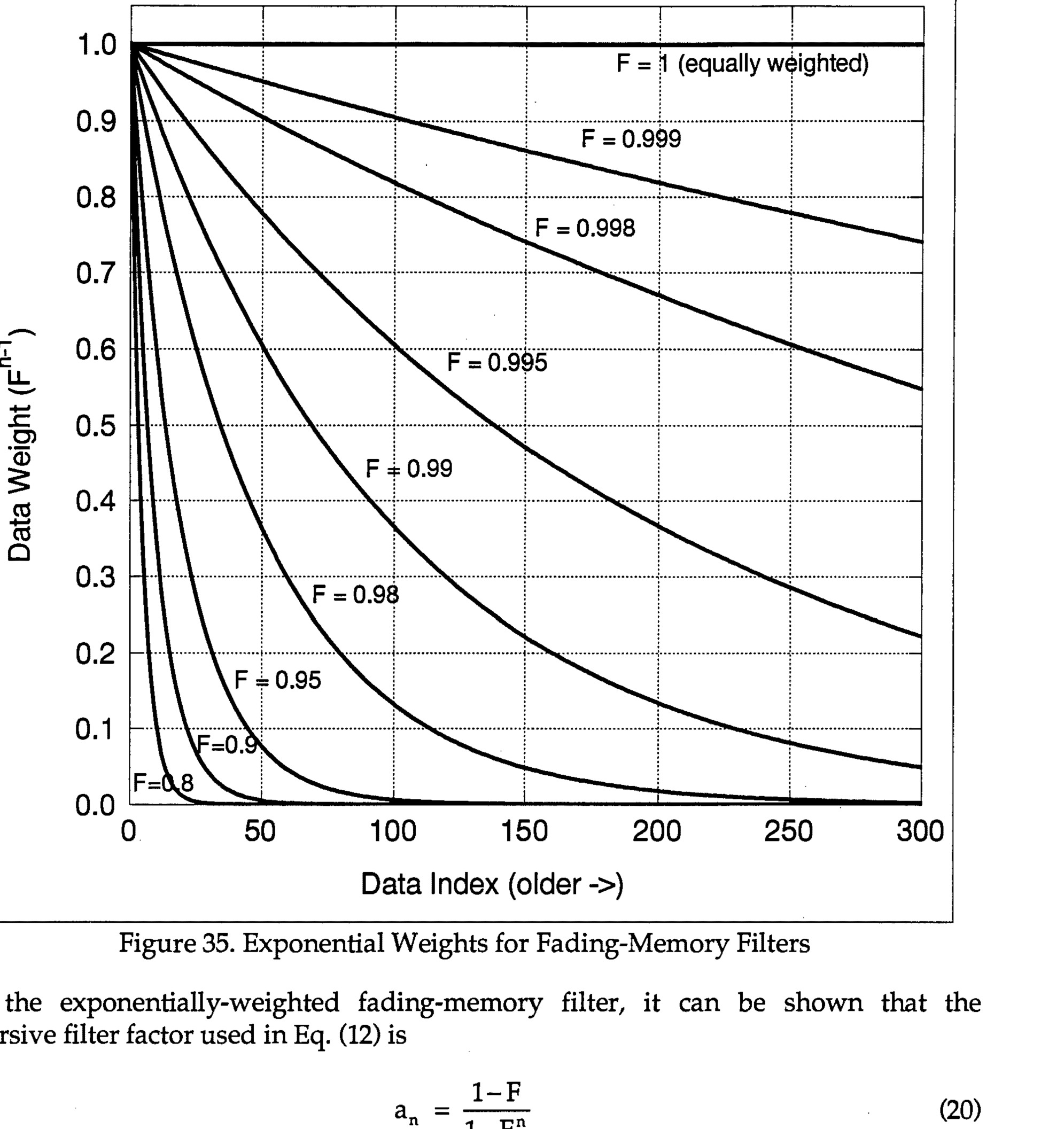
Figure 35. Exponential Weights for Fading-Memory Filters
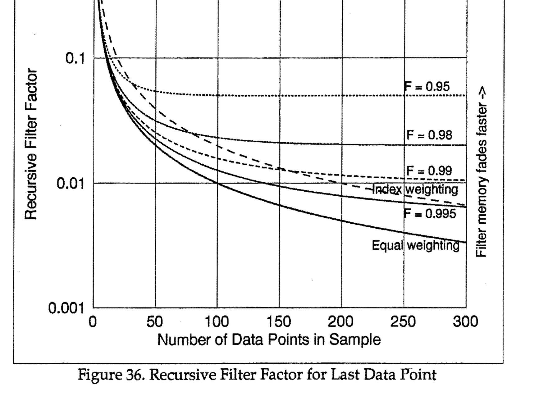
Figure 36. Recursive Filter Factor for Last Data Point
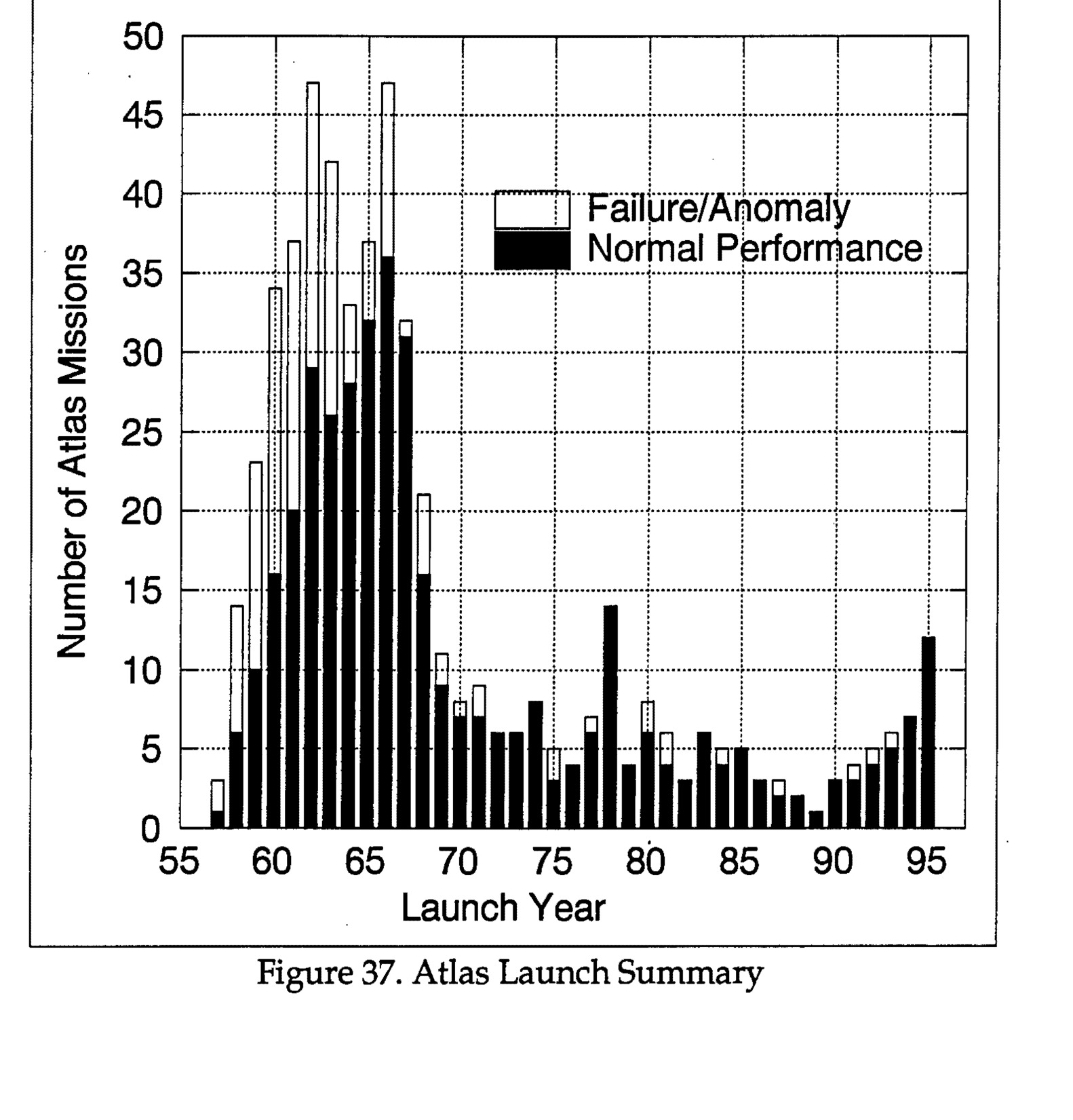
Figure 37. Atlas Launch Summary - Bar graph showing Number of Atlas Missions (0-50) vs Launch Year (55-95), with bars split between Failure/Anomaly (white) and Normal Performance (black)
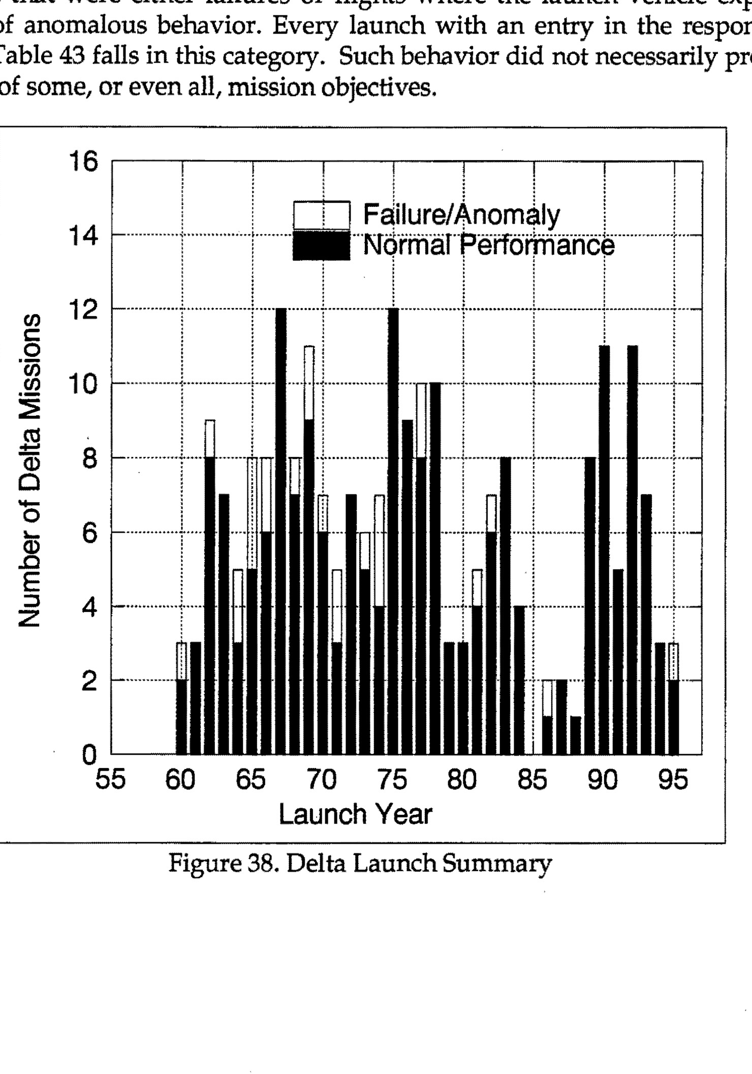
Figure 38. Delta Launch Summary - Bar graph showing Number of Delta Missions (0-16) vs Launch Year (55-95), with bars split between Failure/Anomaly (white) and Normal Performance (black)
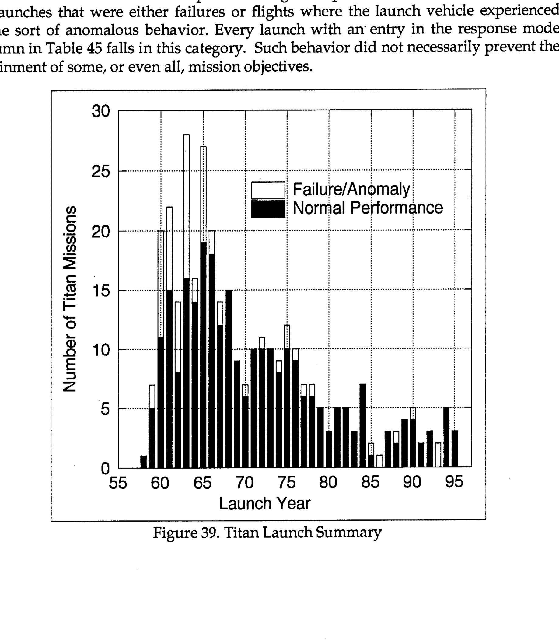
Figure 39. Titan Launch Summary - Bar graph showing Number of Titan Missions (y-axis, 0-30) vs Launch Year (x-axis, 55-95), with bars divided into Normal Performance (solid black) and Failure/Anomaly (clear white)
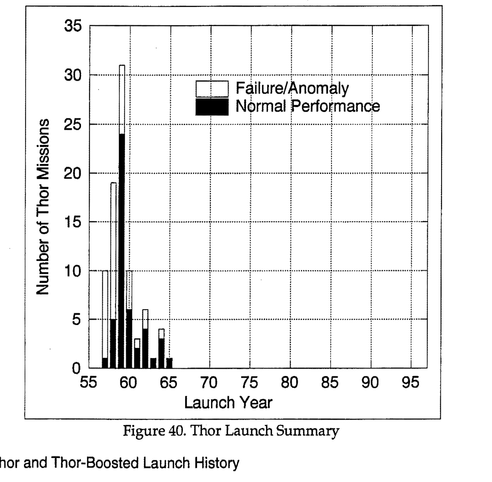
Figure 40. Thor Launch Summary - Bar graph showing Thor missions by launch year with normal performance and failure/anomaly breakdown
Emblem of the 30th Space Wing, with text '30TH SPACE WING' on a scroll at the bottom.
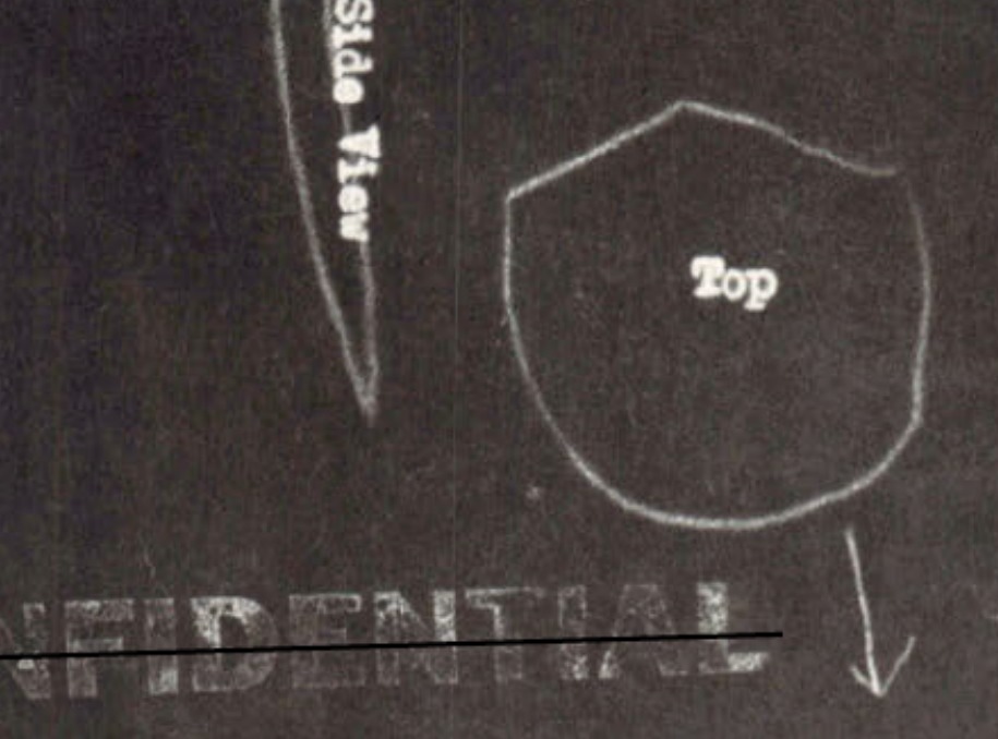
Hand-drawn diagram showing side view and top view of observed craft with annotations about movement and dimensions
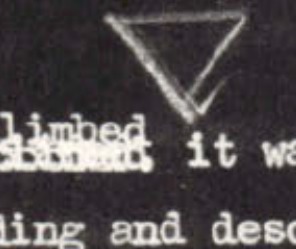
Sketch A - inverted triangle/cone shape

Sketch B - upright triangle shape
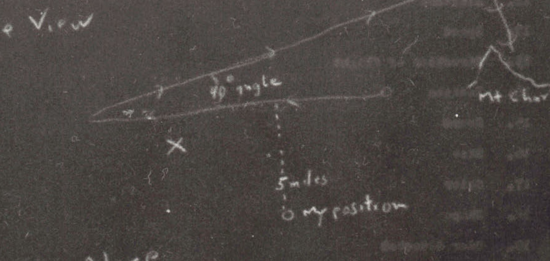
Side view diagram showing flight path with 5 mile markers to Las Vegas and Henderson
Top-down view diagram with compass directions showing flight path and 5 mi deviation from observer position
Hand-drawn diagram showing canyon cross-section with measurements, including '30 ft' notation and directional arrow
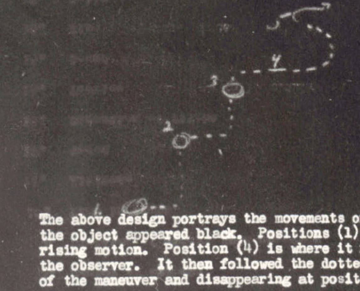
Diagram showing numbered positions (1) through (5) with dotted line indicating object's flight path and maneuver
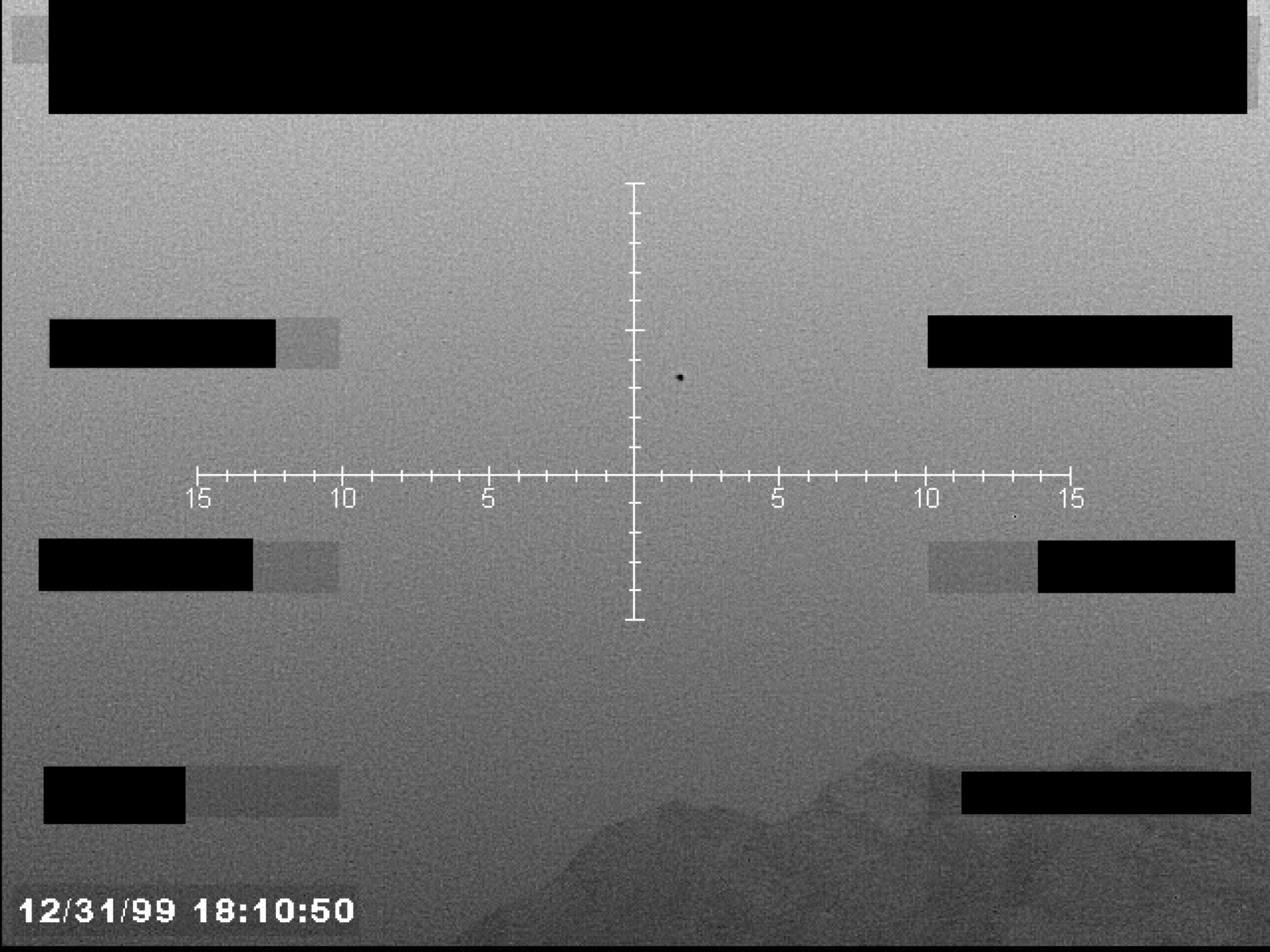
Sensor display view with a central crosshair, numerical markings on the horizontal axis, and a timestamp. A small dark object is visible near the center.
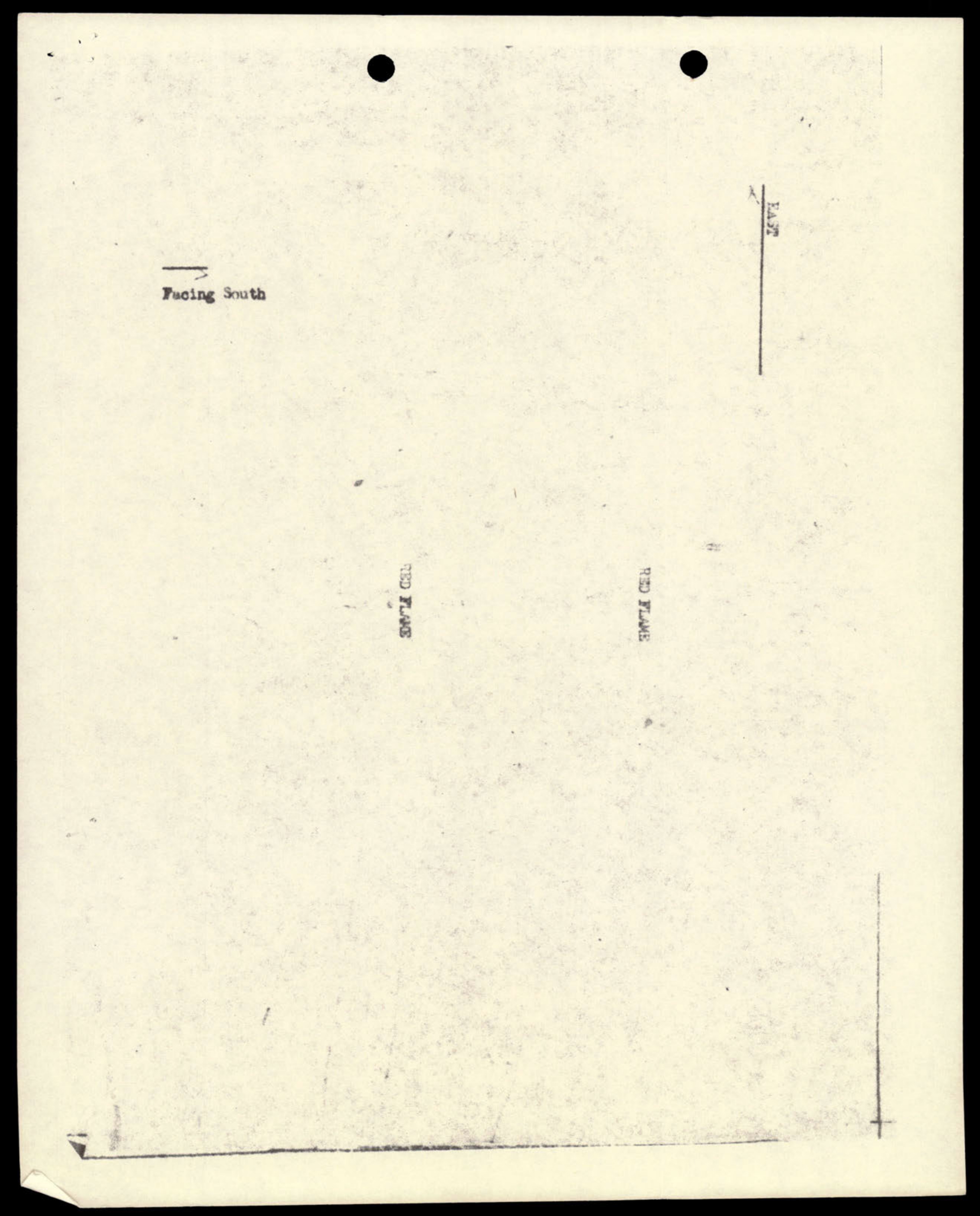
A simple diagram showing direction of travel (East) and 'red flame'.
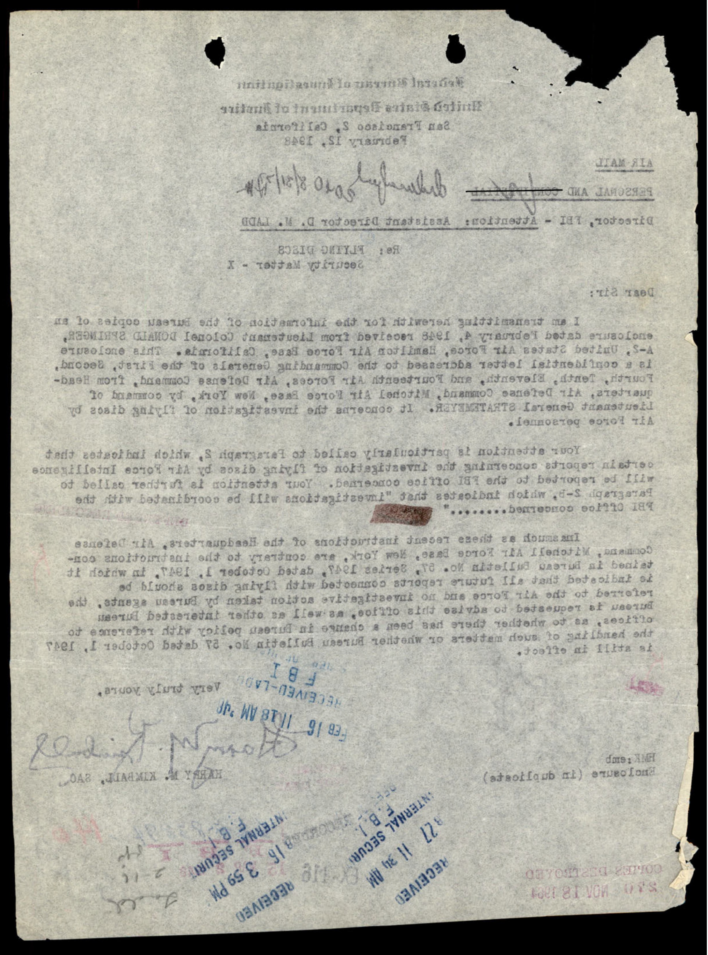
A mirror-image (reversed) carbon copy of the previous page.

Illustration of a bird on a pine branch.

Seal of the City of Los Angeles
Illustration of the Hotel Lawrence
A manila envelope with a taped-on label indicating 'ENCLOSURE' and 'COPIES DESTROYED'.
The back of a manila envelope with a handwritten file number.

Illustration of a young man holding a 'FLYIN-SAUCER' toy.
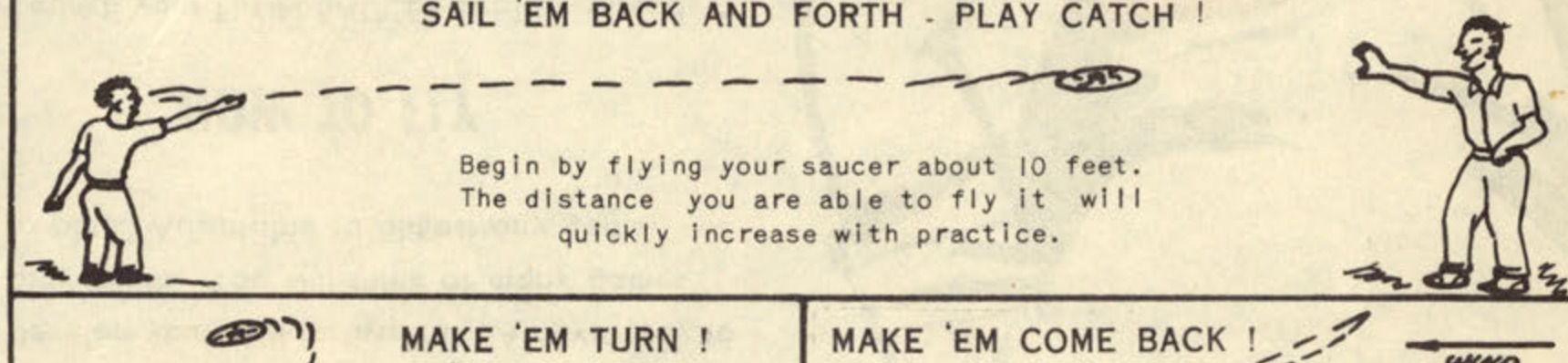
Diagram showing two people playing catch with the saucer.
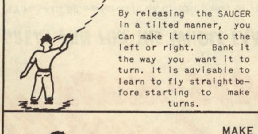
Diagram showing how to make the saucer turn.
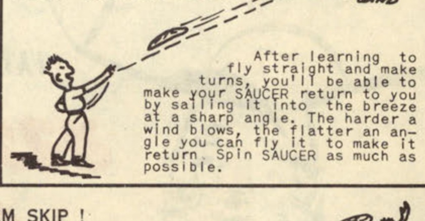
Diagram showing how to make the saucer come back.
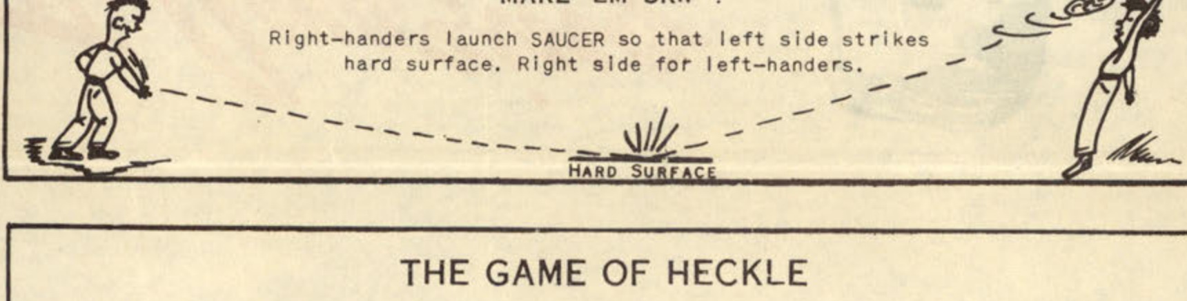
Diagram showing how to make the saucer skip.
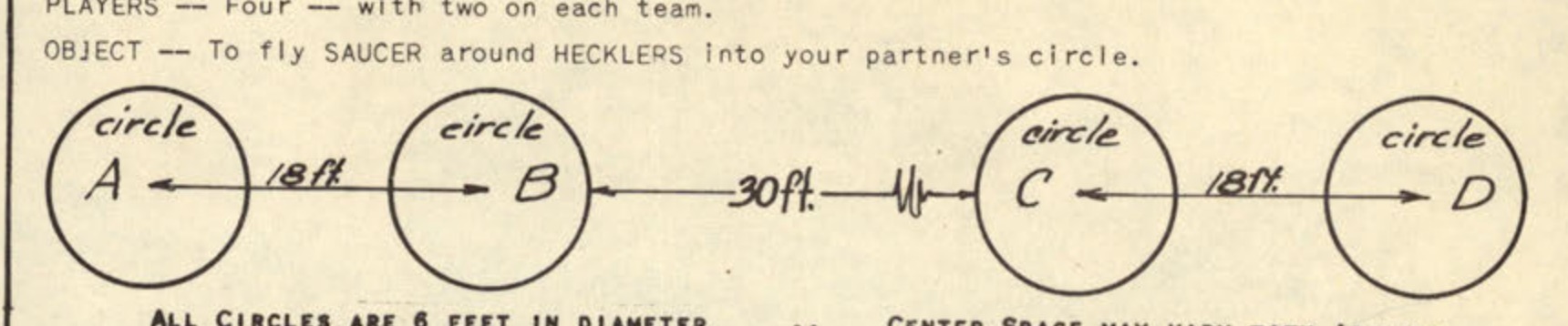
Diagram showing the field layout for 'THE GAME OF HECKLE'.
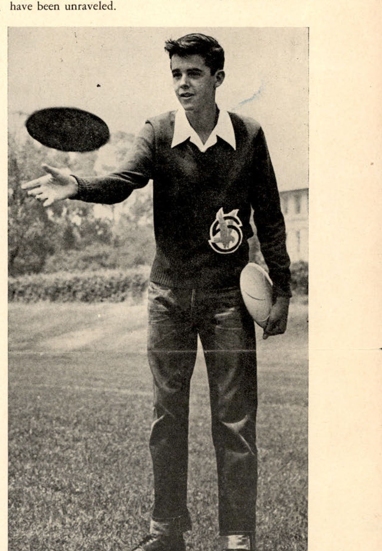
That's a real Flyin' Saucer this young man has just thrown into the air—molded of tough and lightweight cellulose acetate by Southern California Plastic Co., Glendale. Designed in accordance with aerodynamic principles, the Flyin' Saucer spins through the air with the greatest of ease. Note the radial fins on the disc in the boy's left hand.
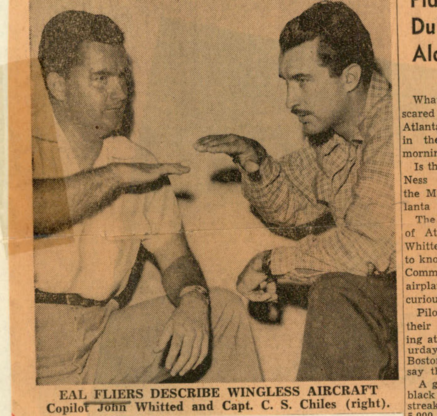
EAL FLIERS DESCRIBE WINGLESS AIRCRAFT Copilot John Whitted and Capt. C. S. Chiles (right).
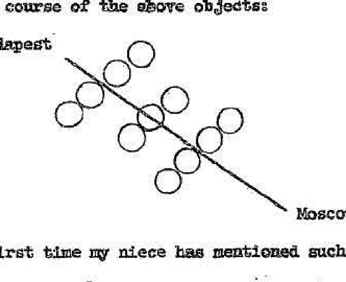
A sketch showing a formation of objects and their suspected course from Budapest to Moscow.
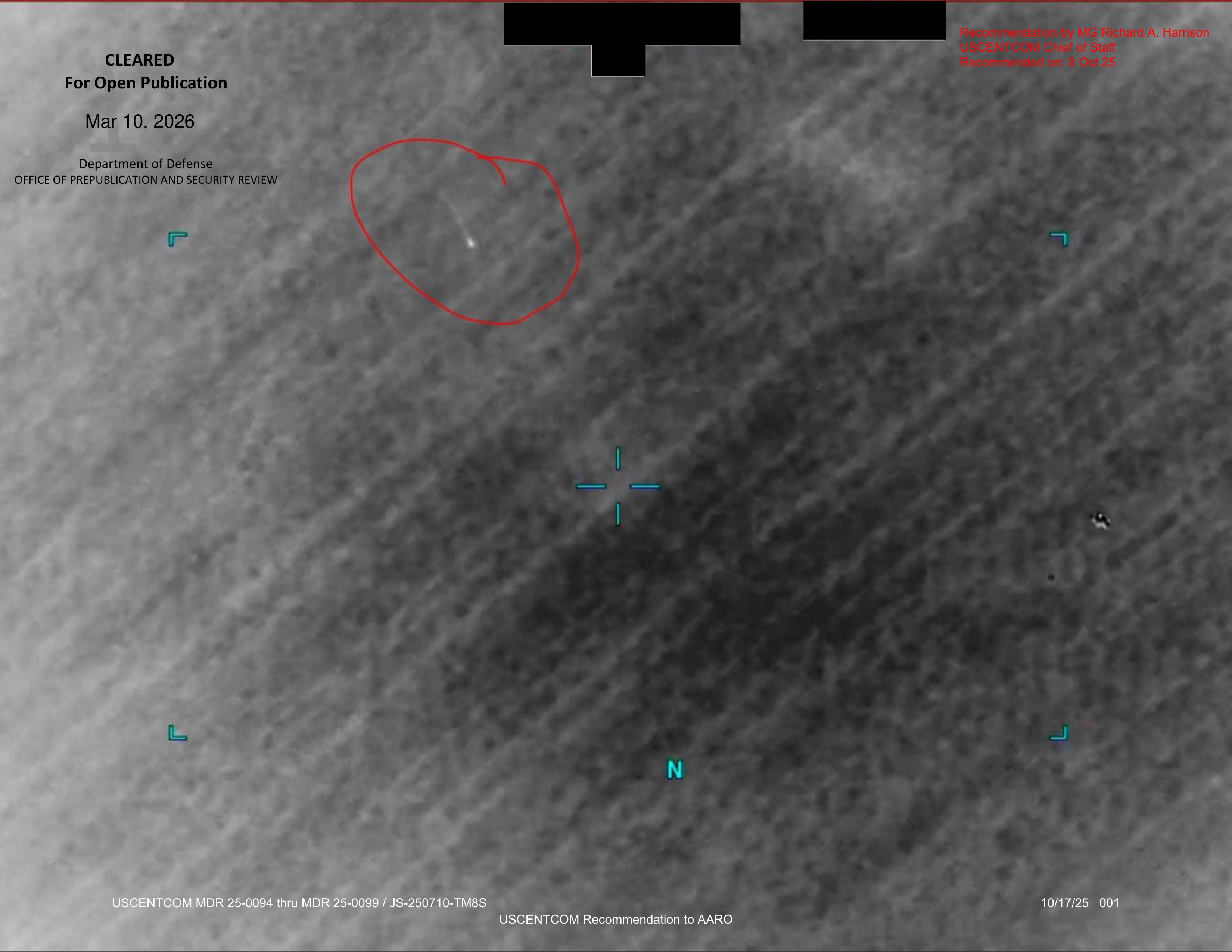
A grayscale sensor image displaying an unidentified luminous object, with targeting reticles and other on-screen data.
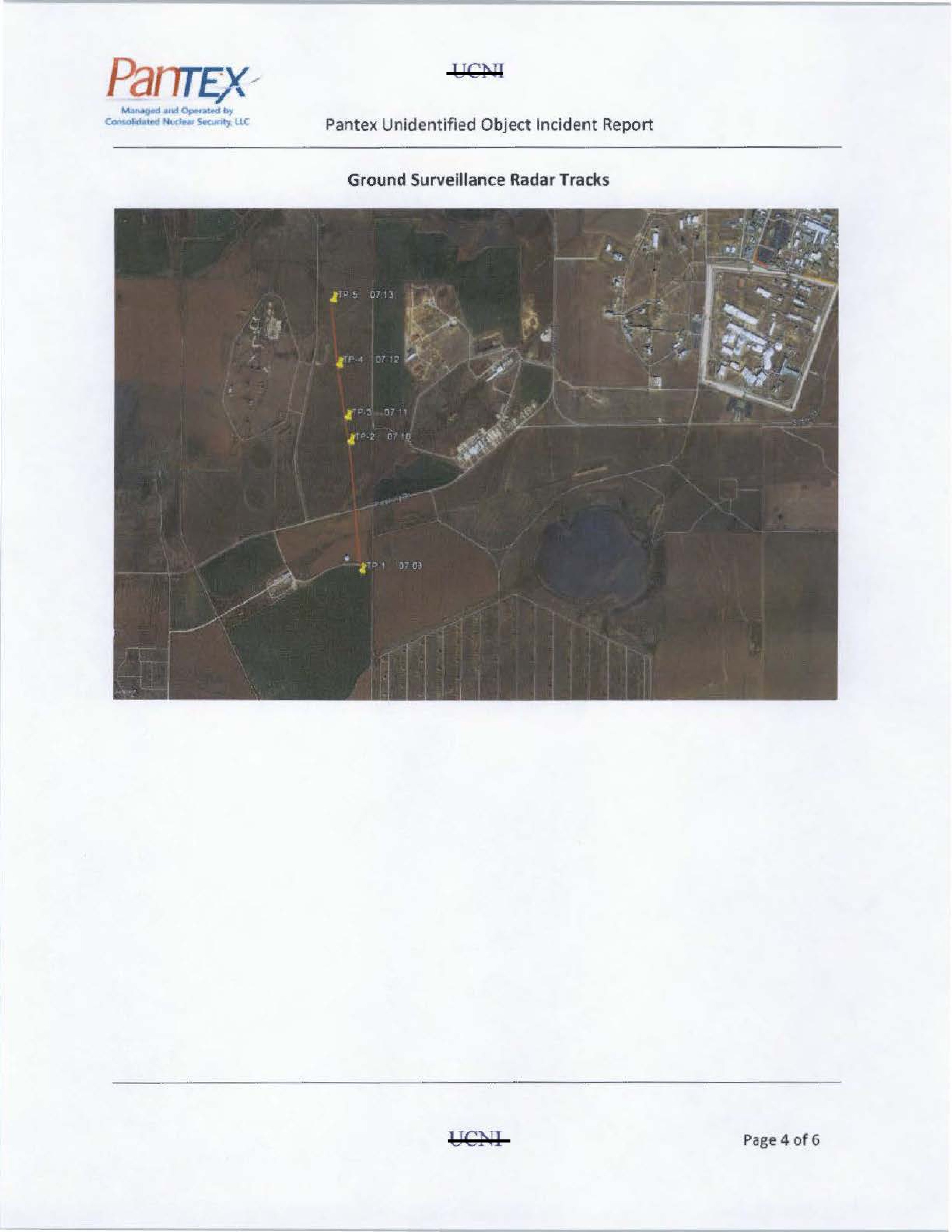
Ground Surveillance Radar Tracks
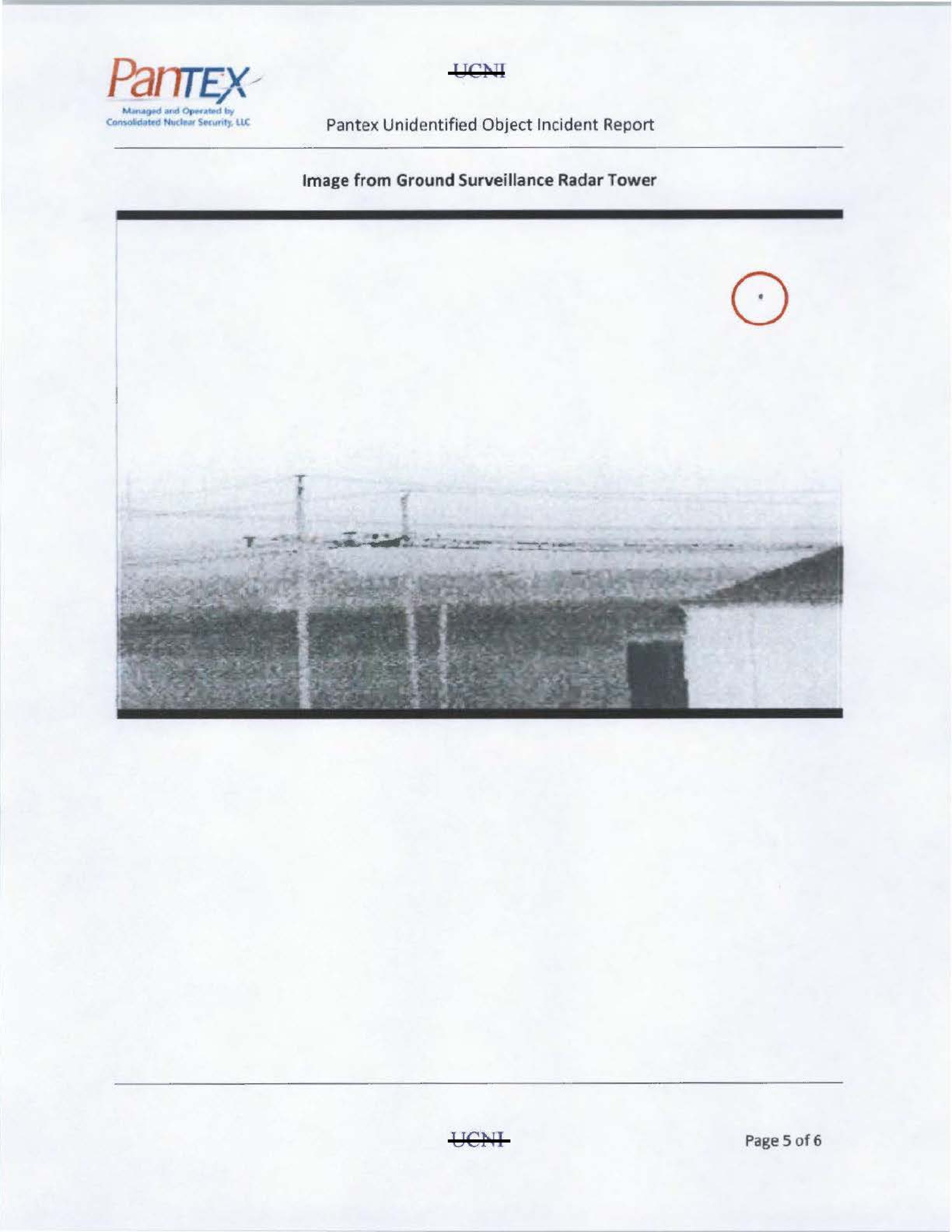
Image from Ground Surveillance Radar Tower
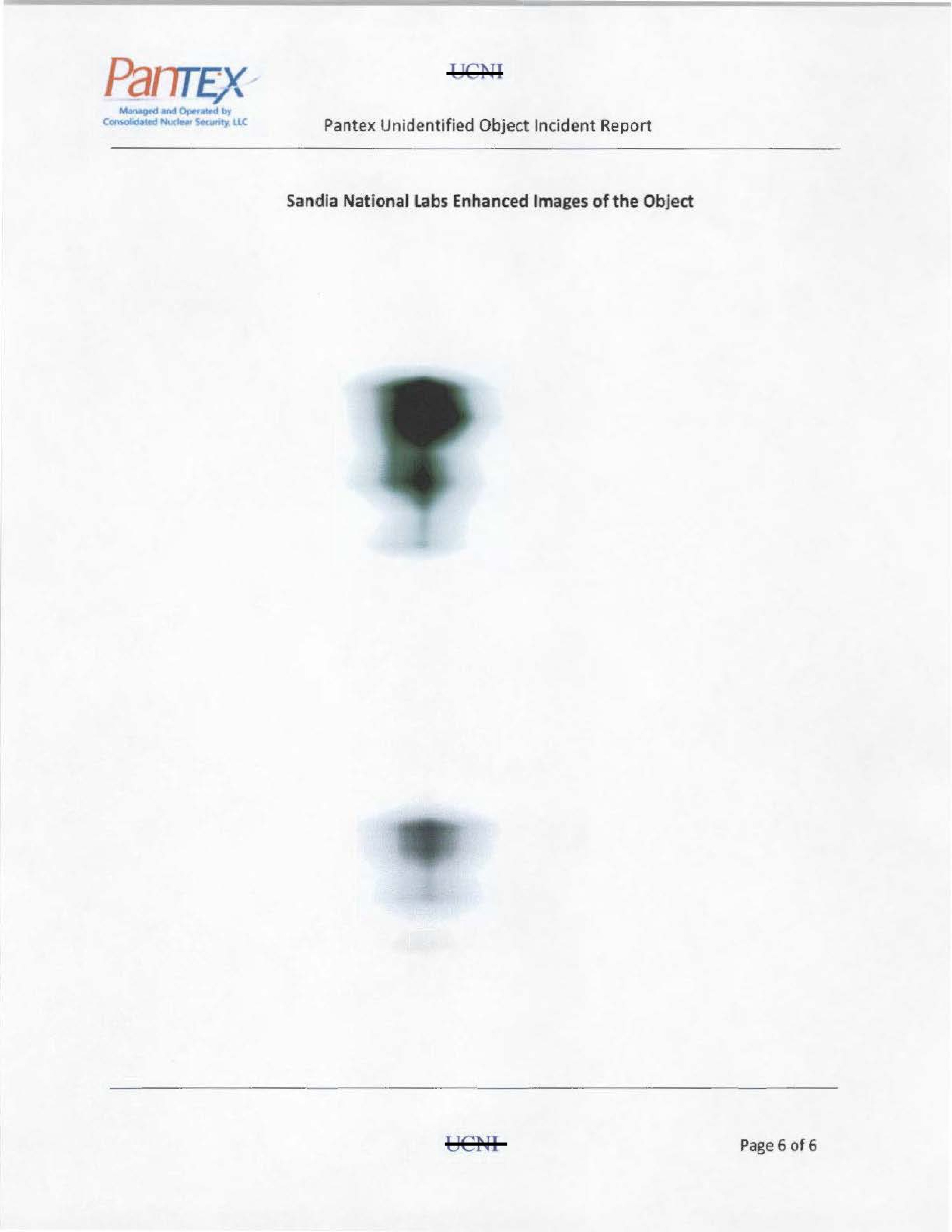
Sandia National Labs Enhanced Images of the Object
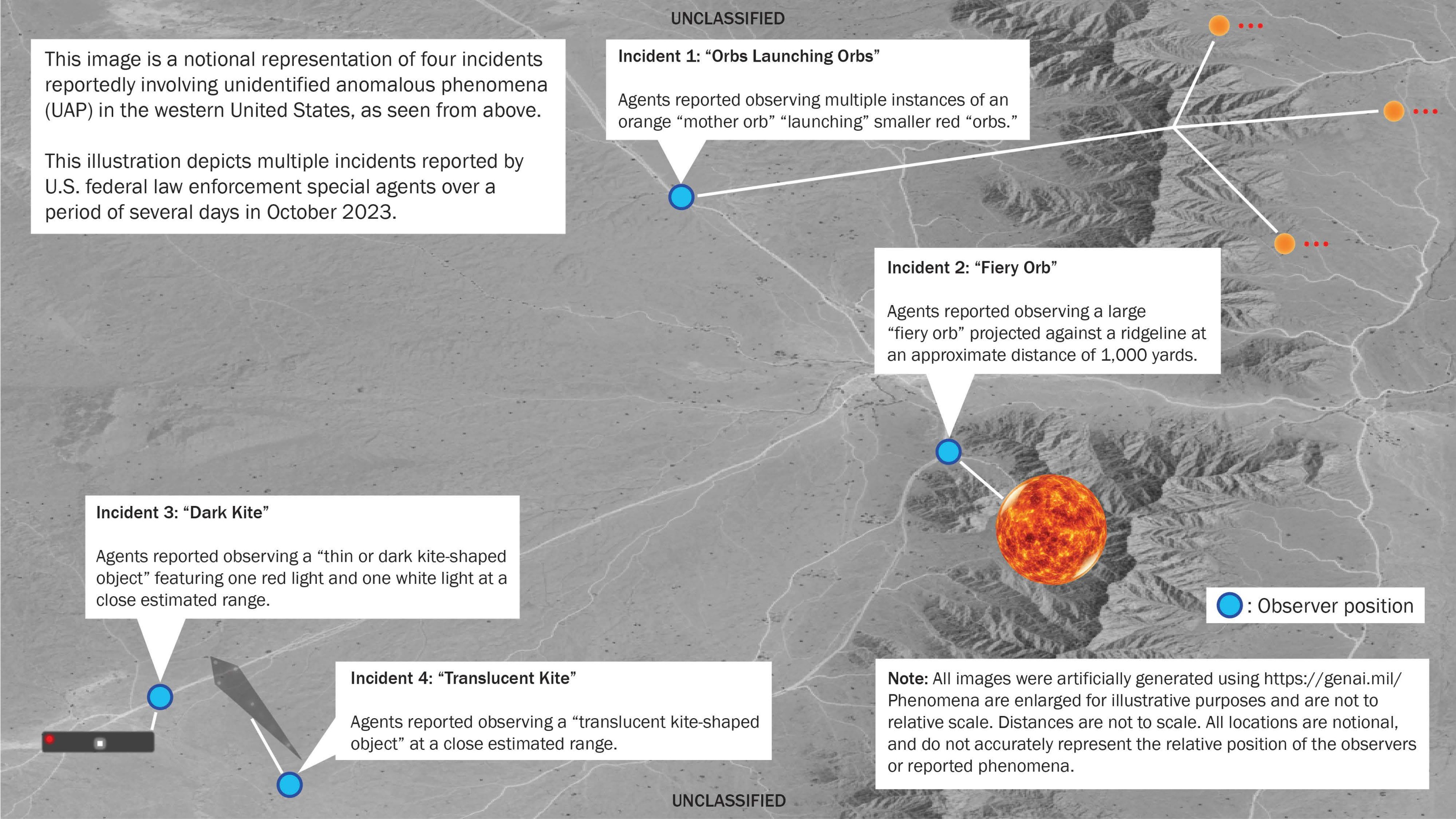
A notional, satellite-view map illustrating four different UAP sightings, including their reported appearance and the positions of observers.
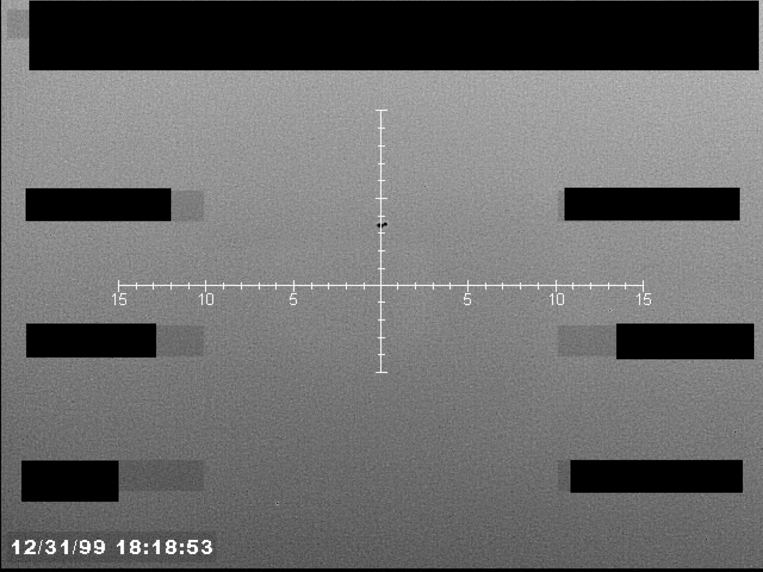
Sensor display with a crosshair reticle and numerical scale.
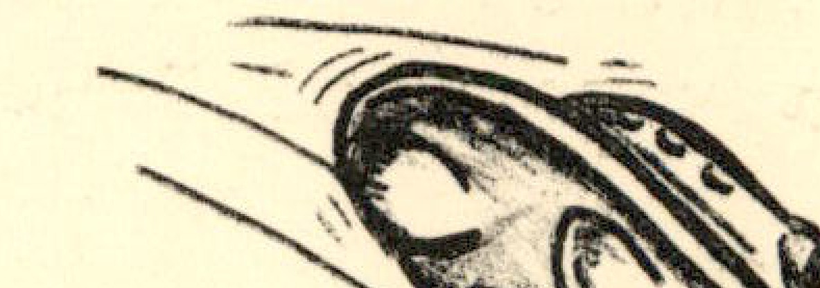
Sketch of a flying saucer.
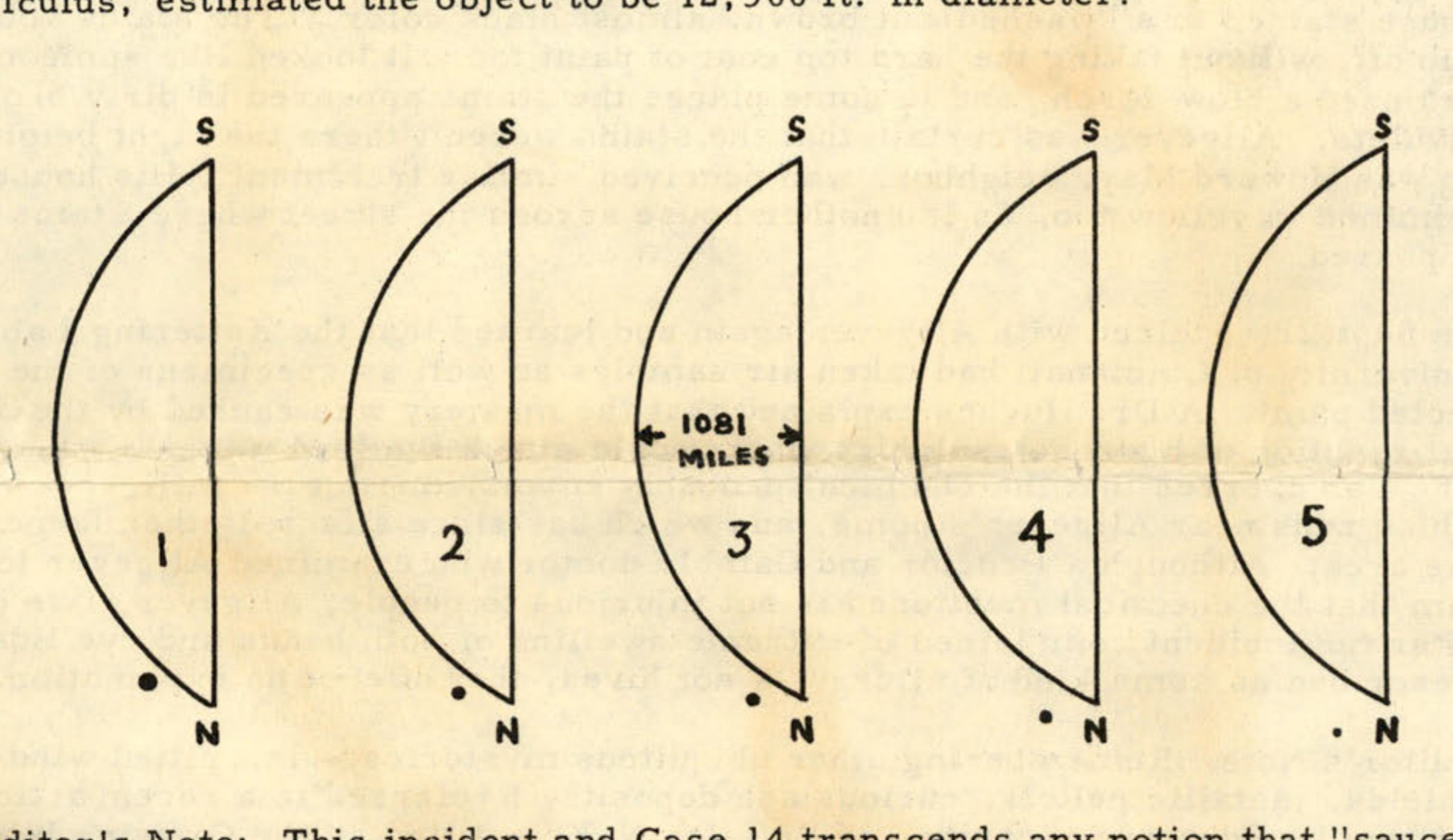
Diagram illustrating an object's size and movement at 4 minute intervals in relation to the moon.
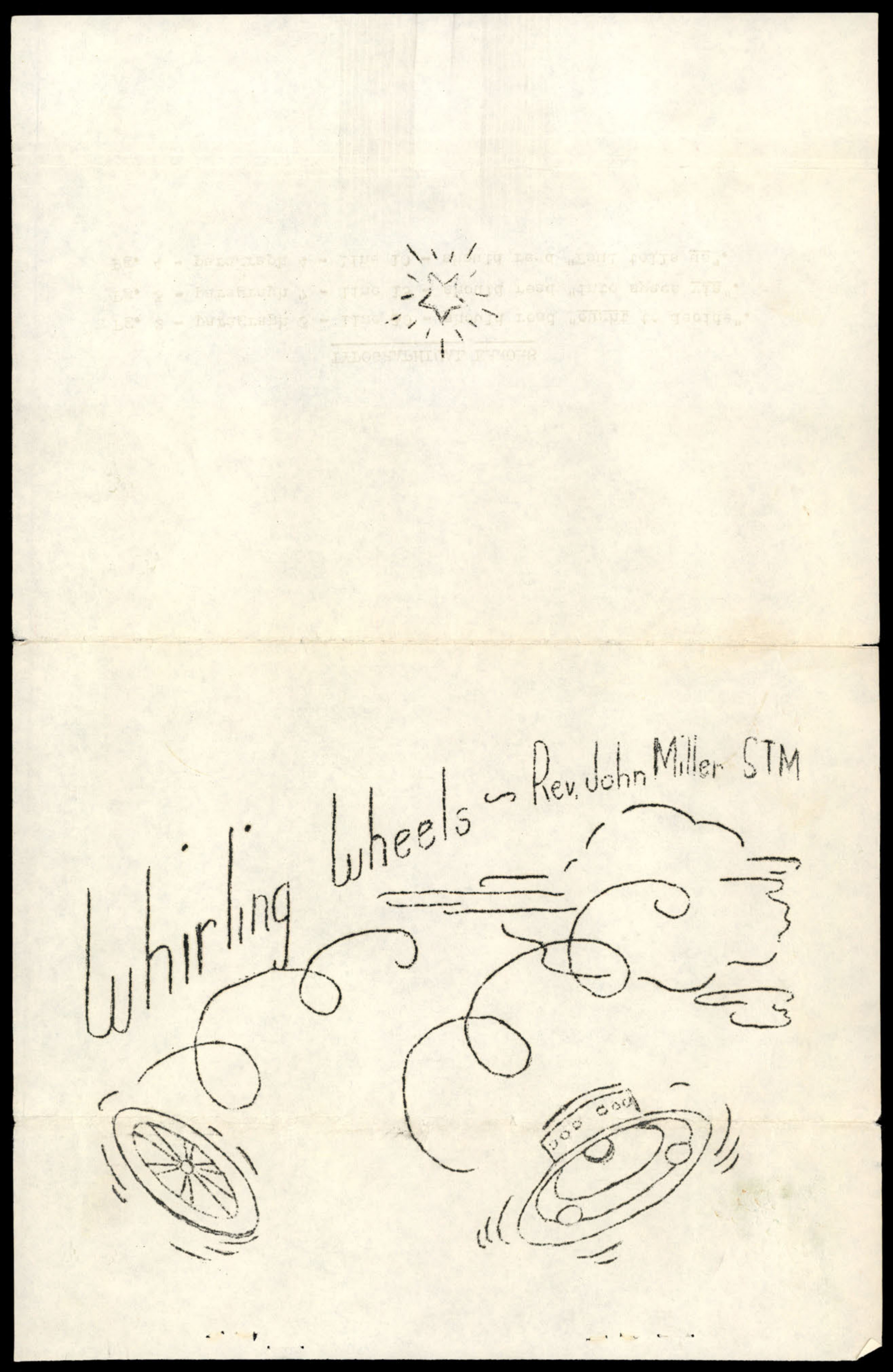
A sketch depicting flying saucers, titled 'whirling wheels'.

Seal of the United States Department of Justice

Hotel logo or emblem at top of page
Lenticular cloud formation
Unpiloted surveillance unit photographed offshore from Los Angeles in 1989
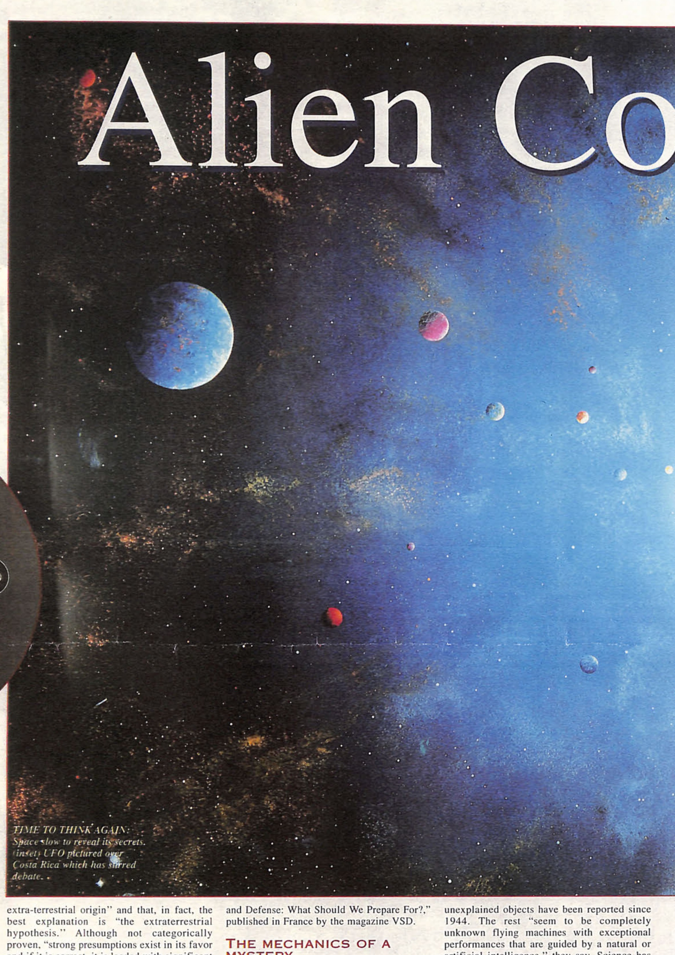
Space scene with planets and title 'Alien Co' with circular inset photo showing unidentified object
Space scene with planets and stars, titled 'ncept' at top
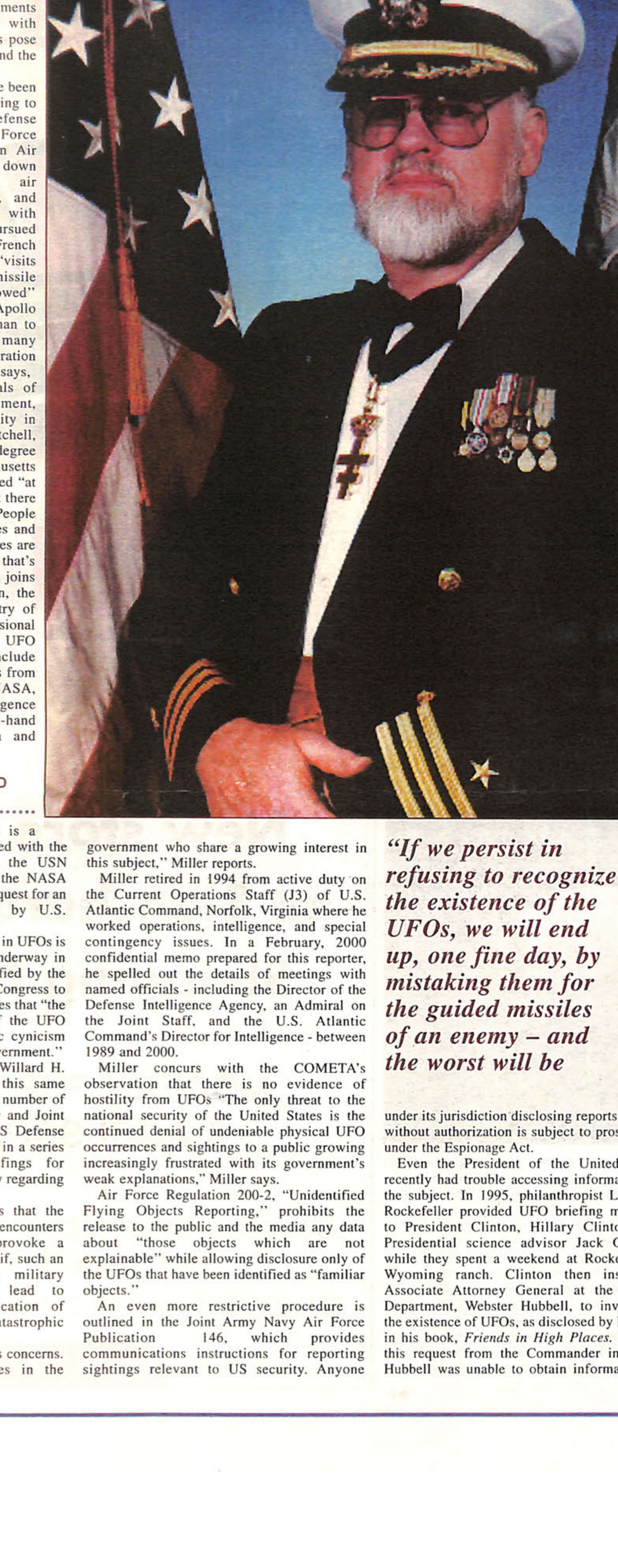
US Naval Reserve Commander Willard H. Miller in military dress uniform with medals
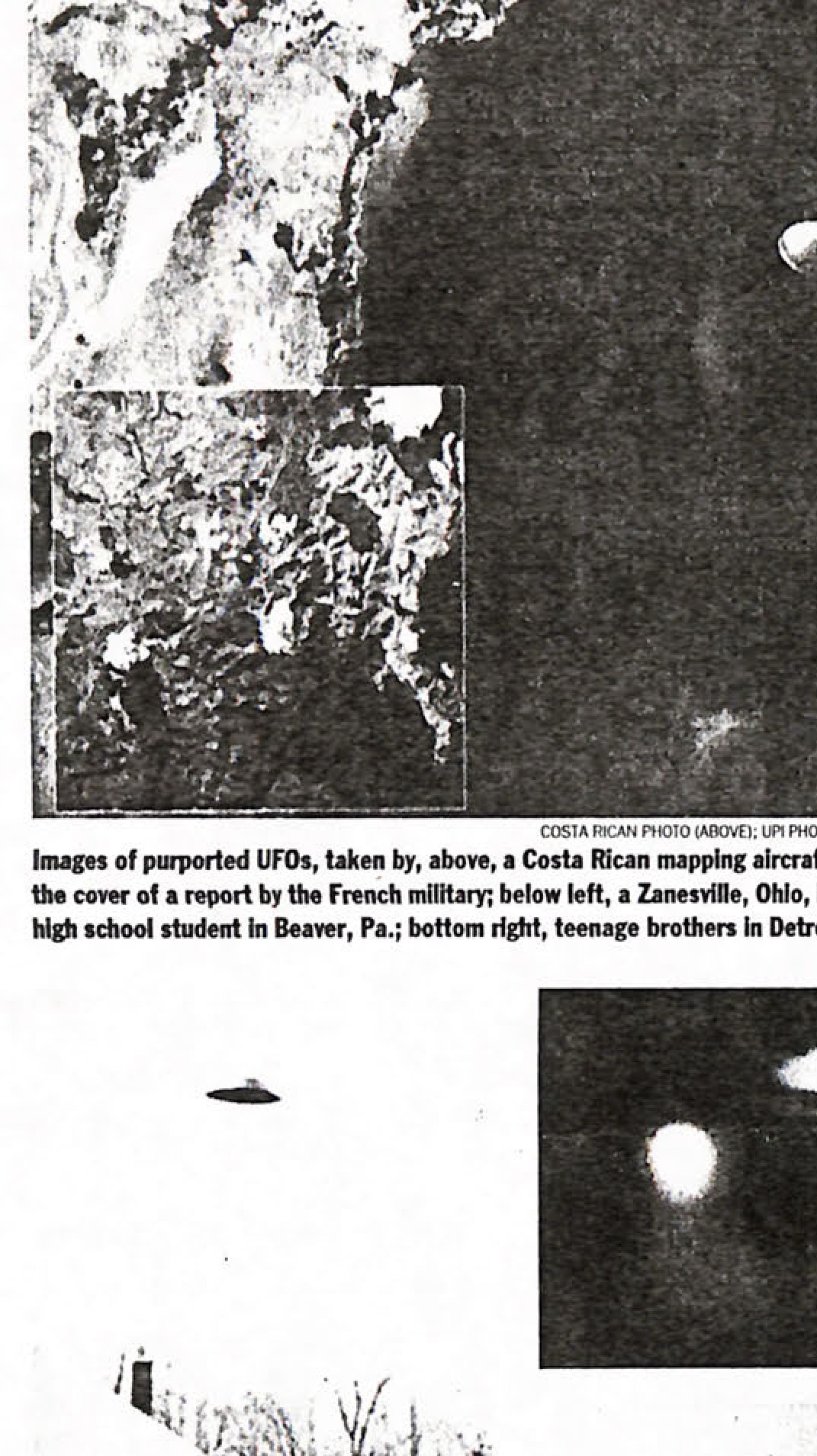
Images of suspected UFOs, taken in above, a Costa Rica mapping aircraft in 1971 at left; a photograph on the cover of a report by the French military; below left, a Zanesville, Ohio, barber in 1966; below right, a high school student in Beaver, Pa.; bottom right, teenage brothers in Detroit in 1967.

Seal of the Department of War, Intelligence and Security.
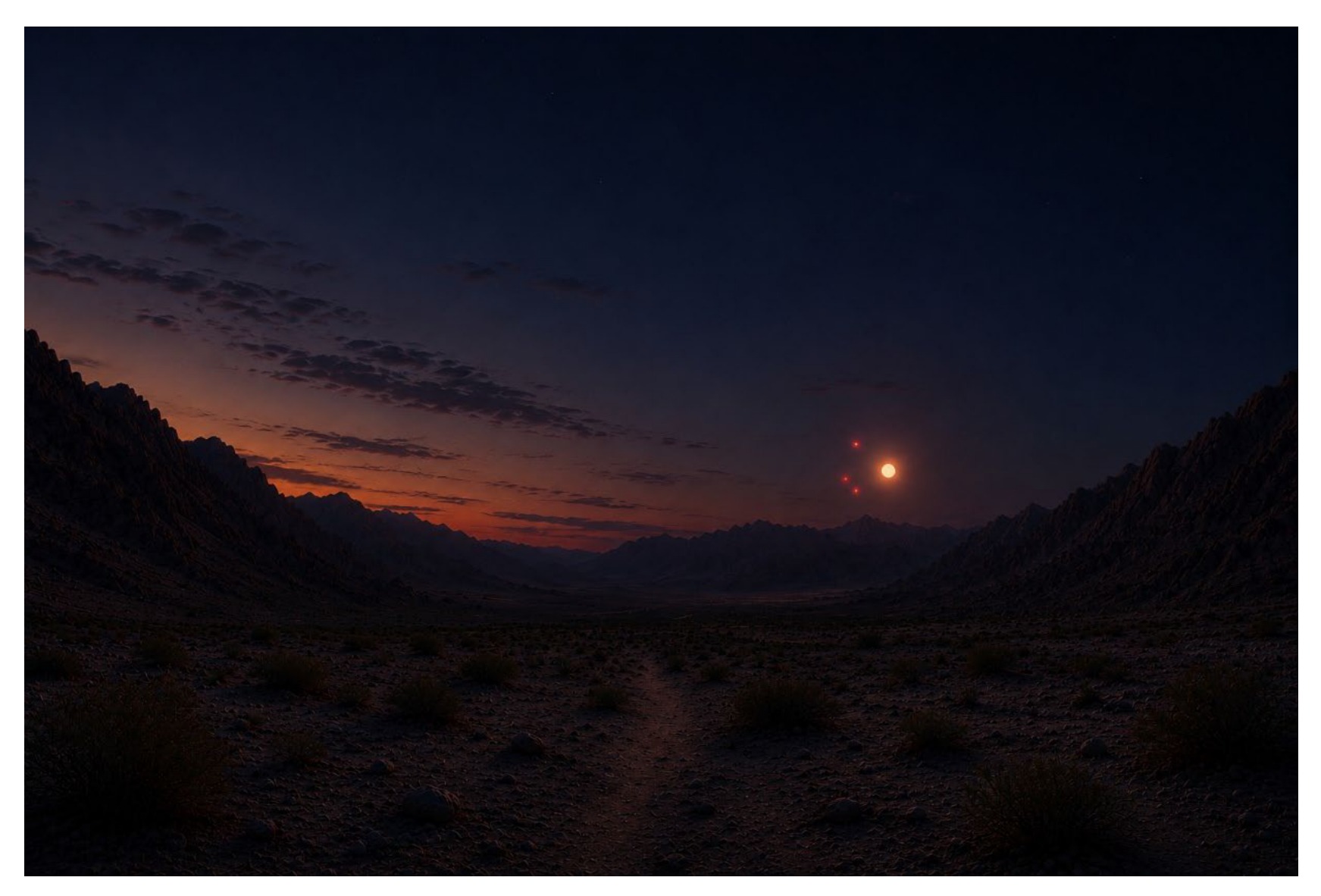
AI-generated image for Incident 1, showing orbs in a dusky mountain valley.
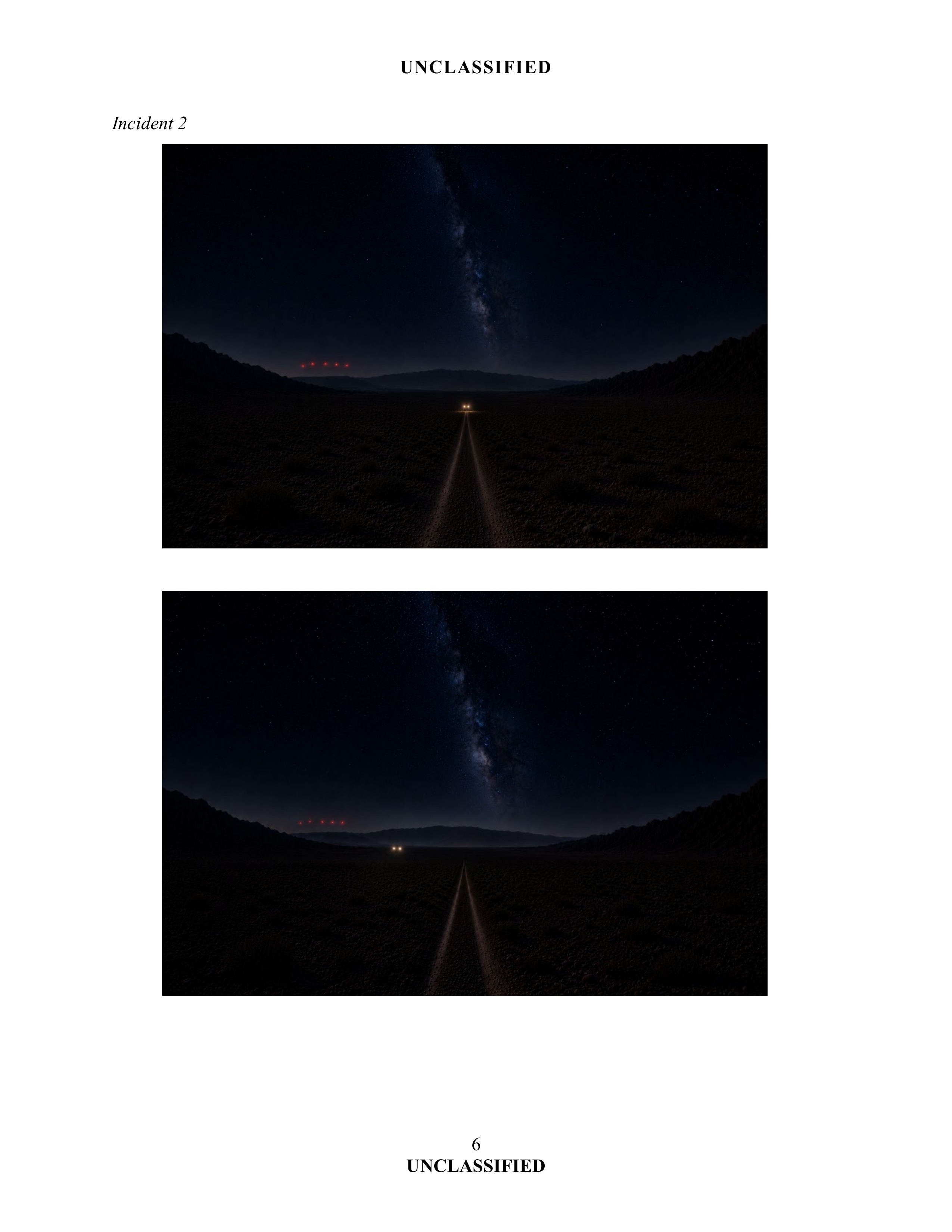
AI-generated image for Incident 2, view 1.
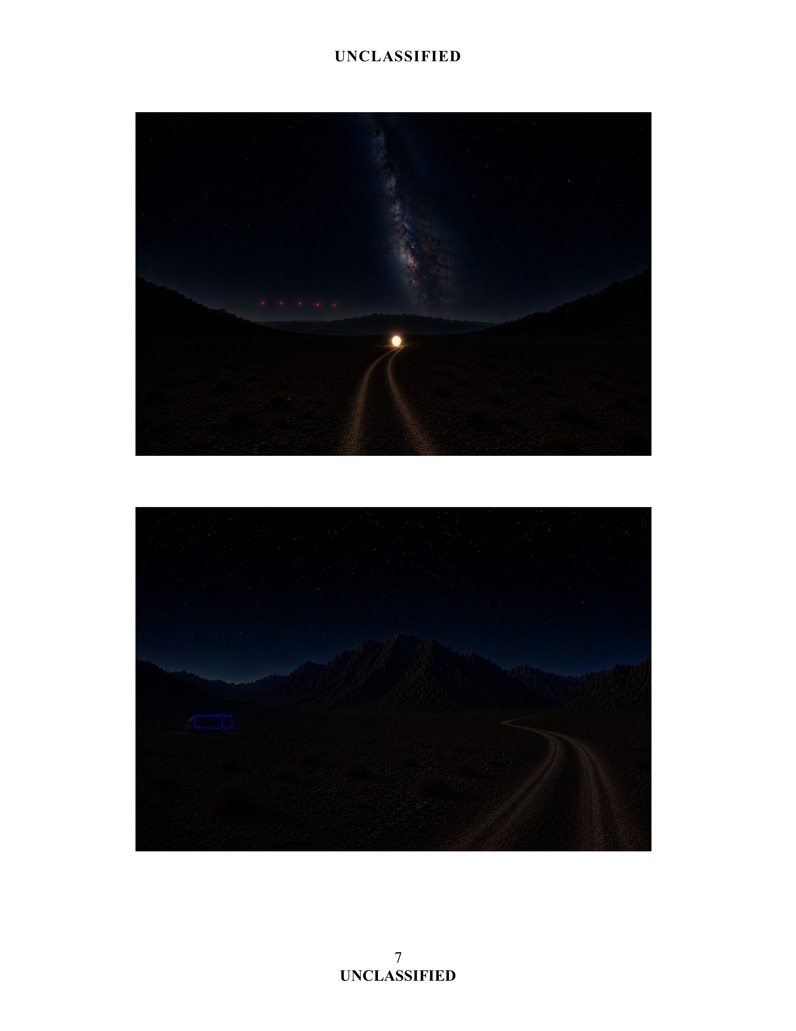
AI-generated image for Incident 2, view 3.
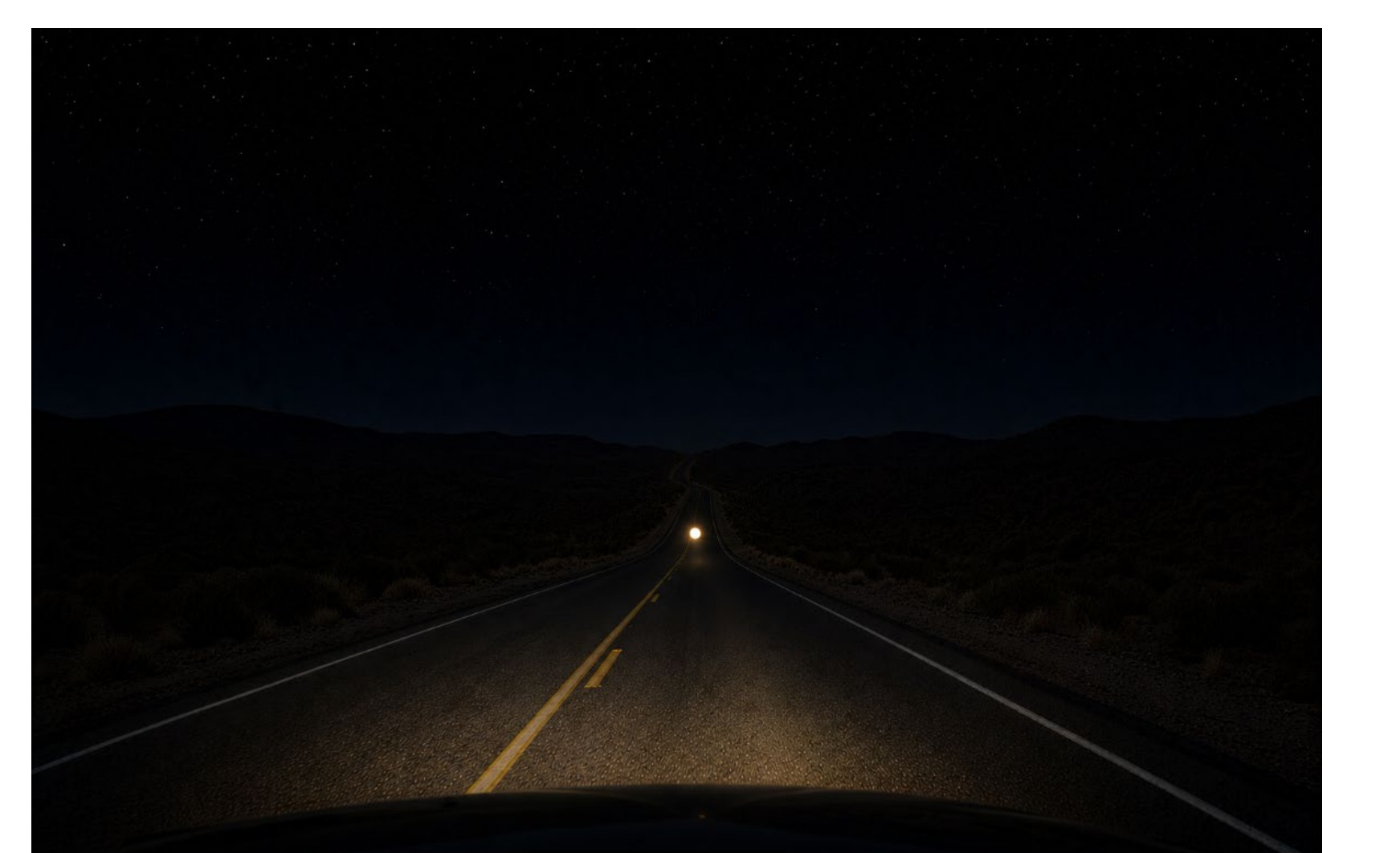
AI-generated image for Incident 3, view 1.
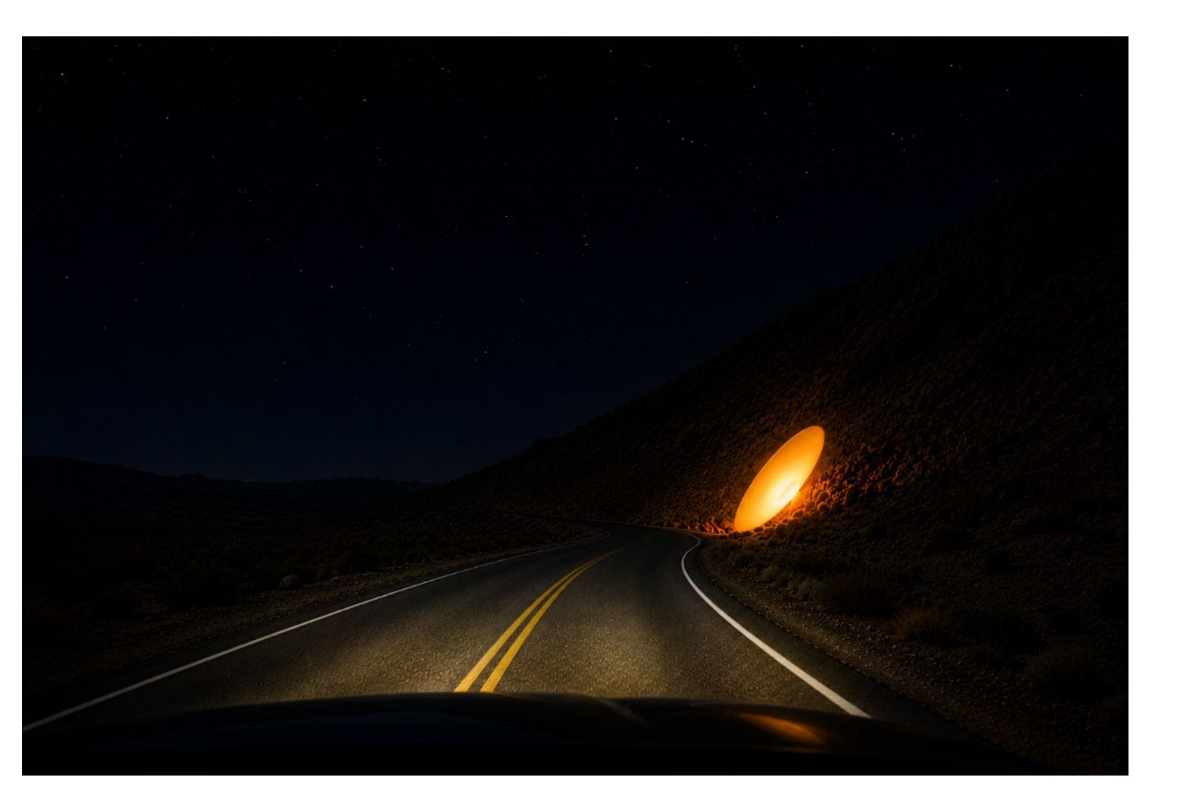
AI-generated image for Incident 3, view 2.

Newspaper masthead: The Evening Journal
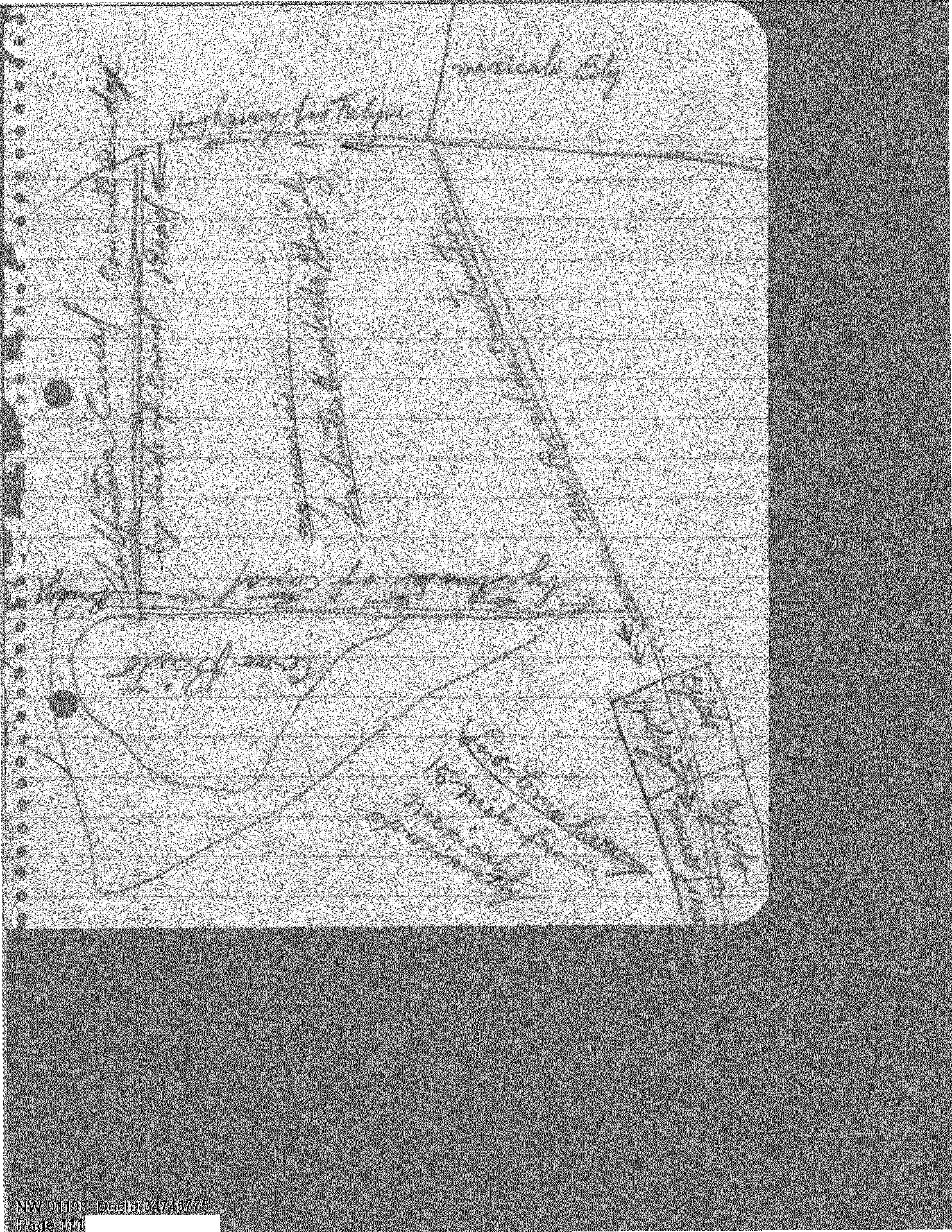
A hand-drawn map showing the location of a UFO sighting near Cerro Prieto, Mexico.

NASA logo

Apollo Program logo
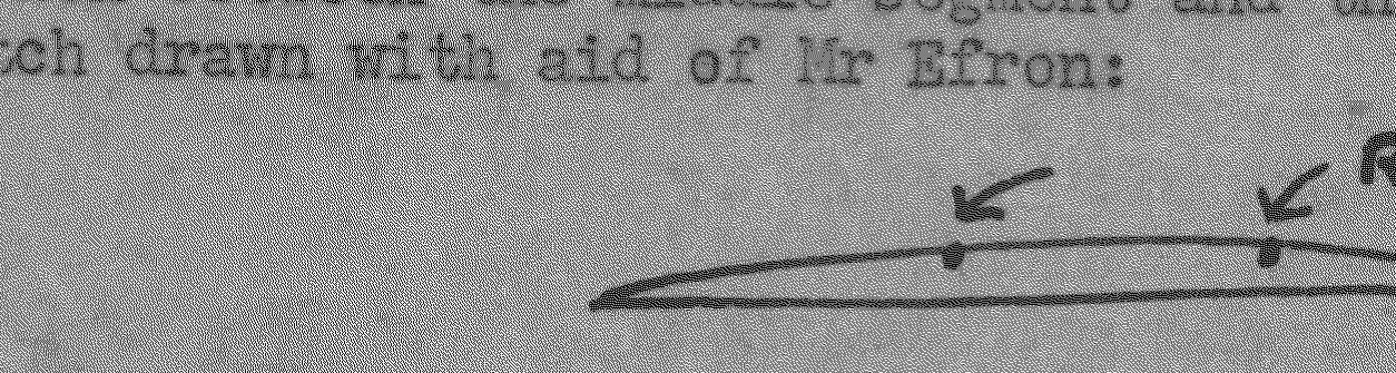
Hand-drawn diagram showing relative position of 2 lights on disc
Two simple sketches showing radar installations - one grid-pattern and one striped pattern
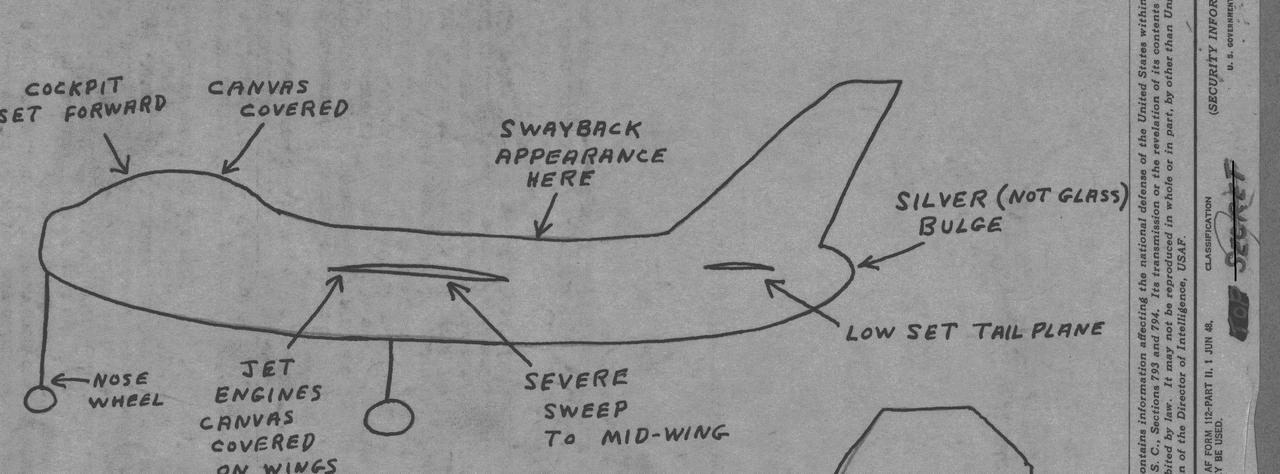
Side profile sketch of jet bomber aircraft with labeled features
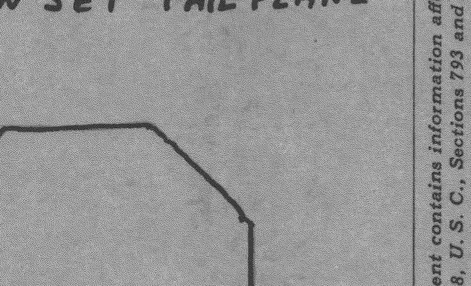
Octagonal design pattern showing brick/asphalt seams at airfield ramp
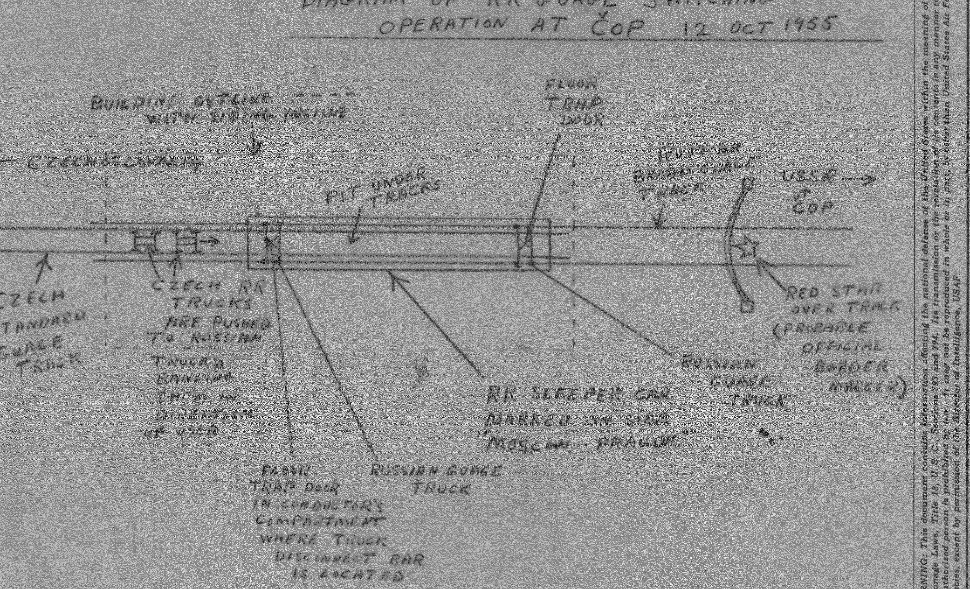
Diagram showing railroad gauge switching operation at Czechoslovakia-USSR border, 12 Oct 1955

A large redacted box labeled '1.4g'.
A green file folder with a white label.
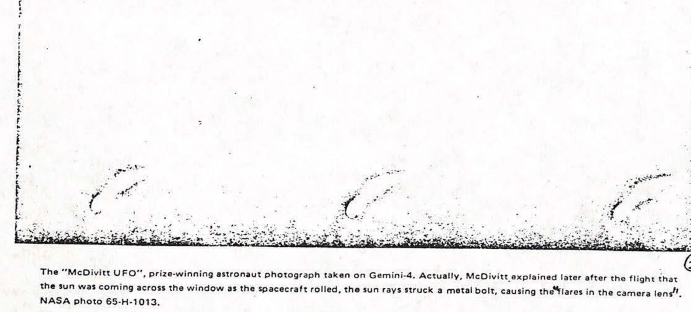
The "McDivitt UFO", prize-winning astronaut photograph taken on Gemini-4. Actually, McDivitt explained later after the flight that the sun was coming across the window as the spacecraft rolled, the sun rays struck a metal bolt, causing the flares in the camera lens. NASA photo 65-H-1013.
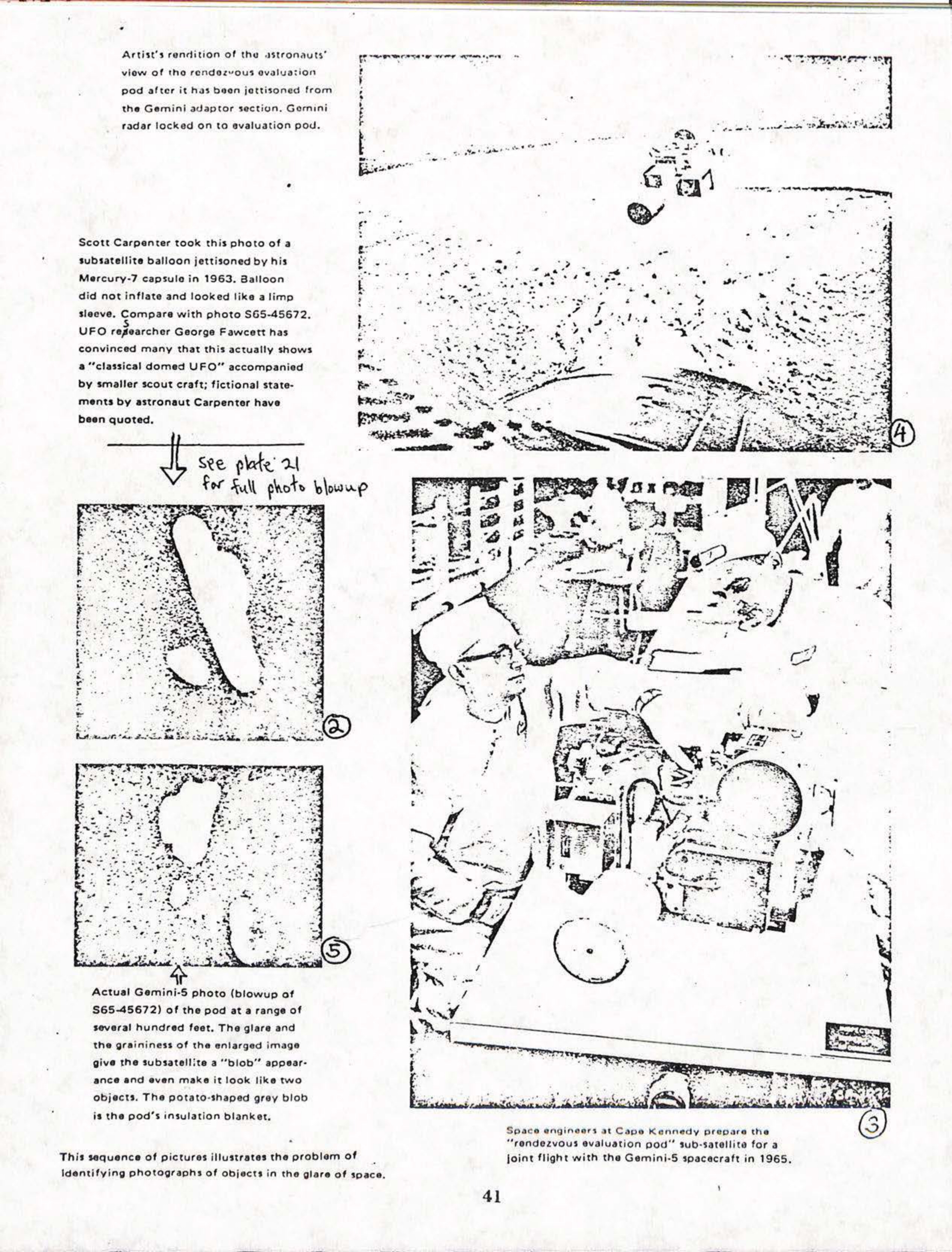
Artist's rendition of the astronauts' view of the rendezvous evaluation pod after it has been jettisoned from the Gemini adaptor section. Gemini radar locked on to evaluation pod.
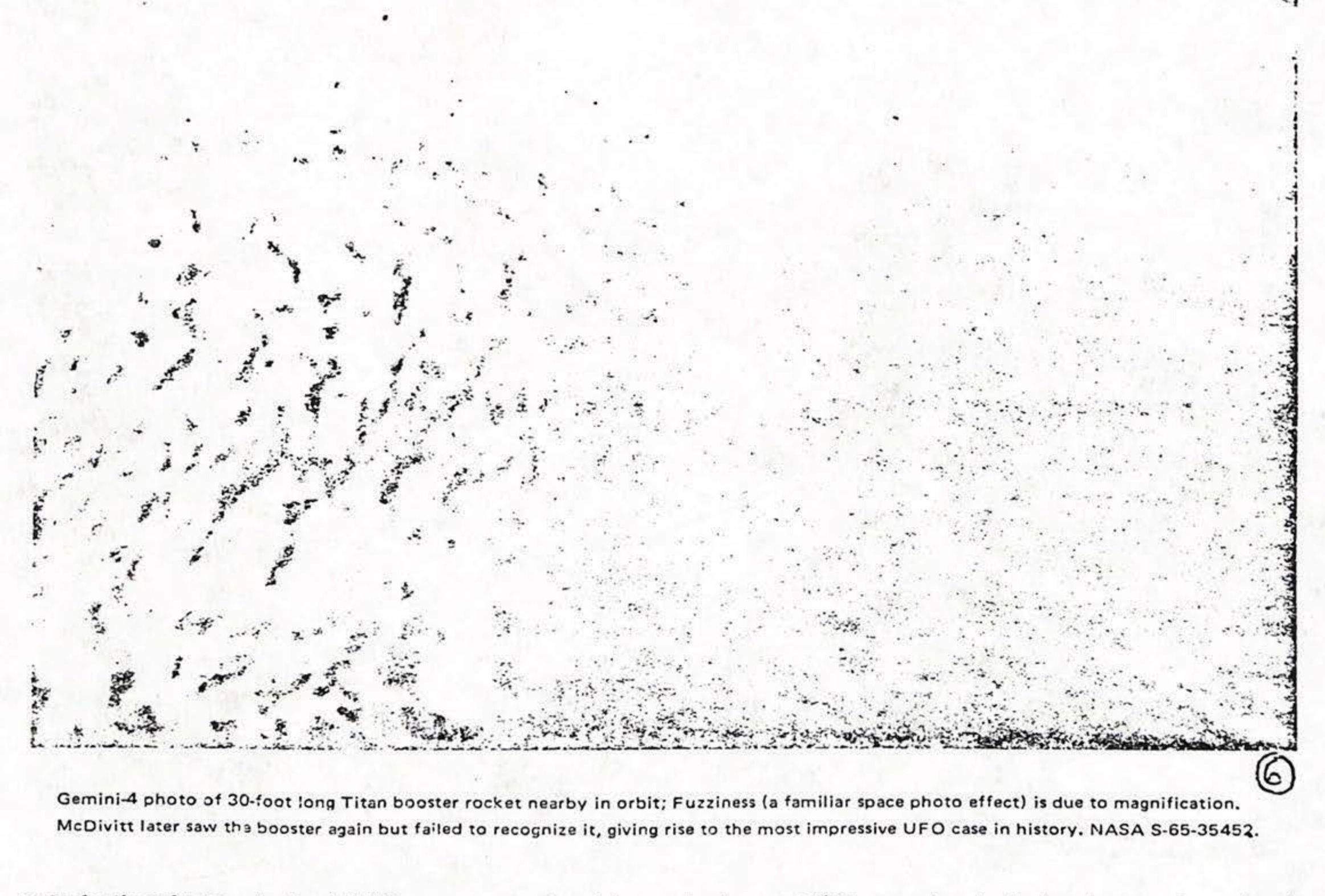
Gemini-4 photo of 30-foot long Titan booster rocket nearby in orbit; Fuzziness (a familiar space photo effect) is due to magnification. McDivitt later saw the booster again but failed to recognize it, giving rise to the most impressive UFO case in history. NASA S-65-35452.
A sketch of an object in space.
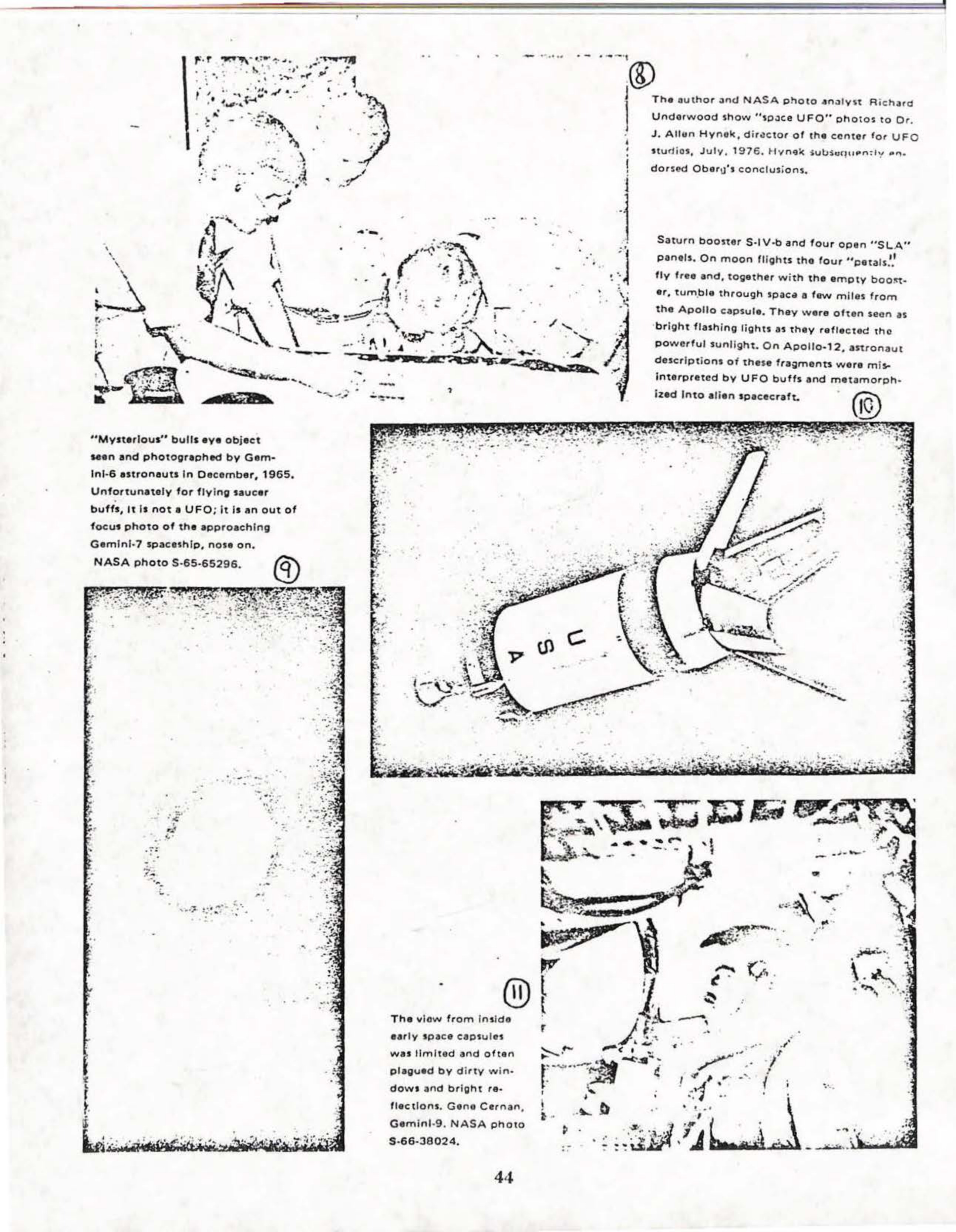
The author and NASA photo analyst Richard Underwood show "space UFO" photos to Dr. J. Allen Hynek, director of the center for UFO studios, July, 1976. Hynek subsequently endorsed Oberg's conclusions.
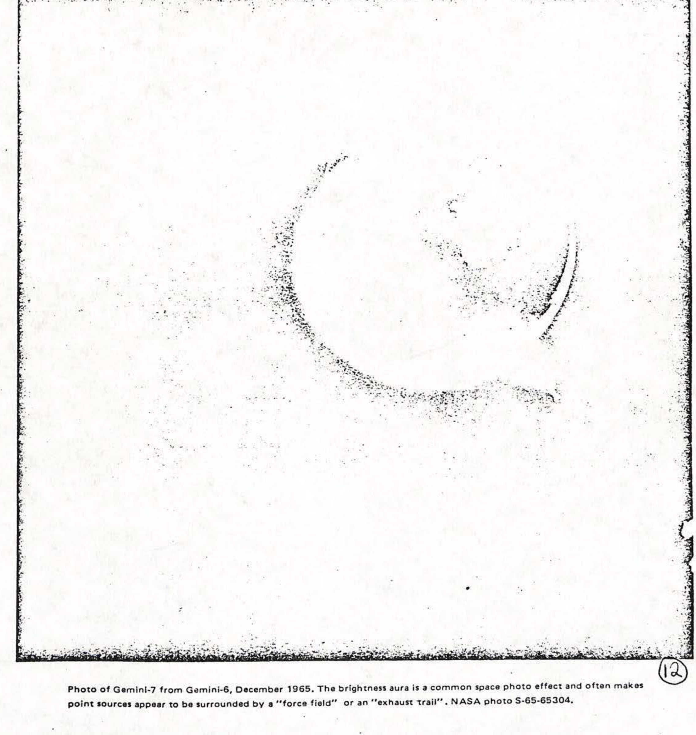
Photo of Gemini-7 from Gemini-6, December 1965. The brightness aura is a common space photo effect and often makes point sources appear to be surrounded by a "force field" or an "exhaust trail". NASA photo S-65-65304.
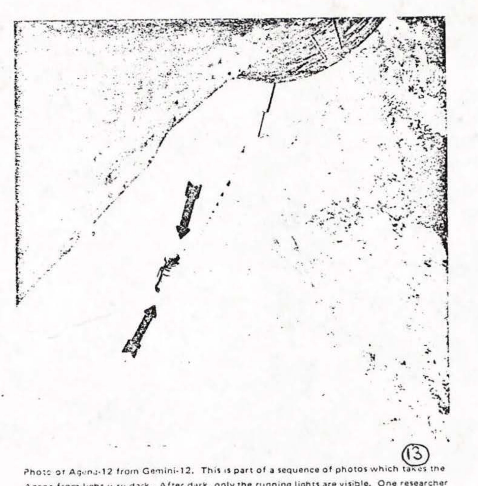
Photo of Agena-12 from Gemini-12. This is part of a sequence of photos which takes the Agena from light to dark. After dark, only the running lights are visible. One researcher has widely published this latter photograph as a "UFO", "said by NASA to be Agena tracking lights". NASA photo S-66-63101.
"Said to be ranging lights" on Gemini-12, according to Sandler. Compare with earlier photo showing Agena in the sunlight. Deliberate slanting of evidence.
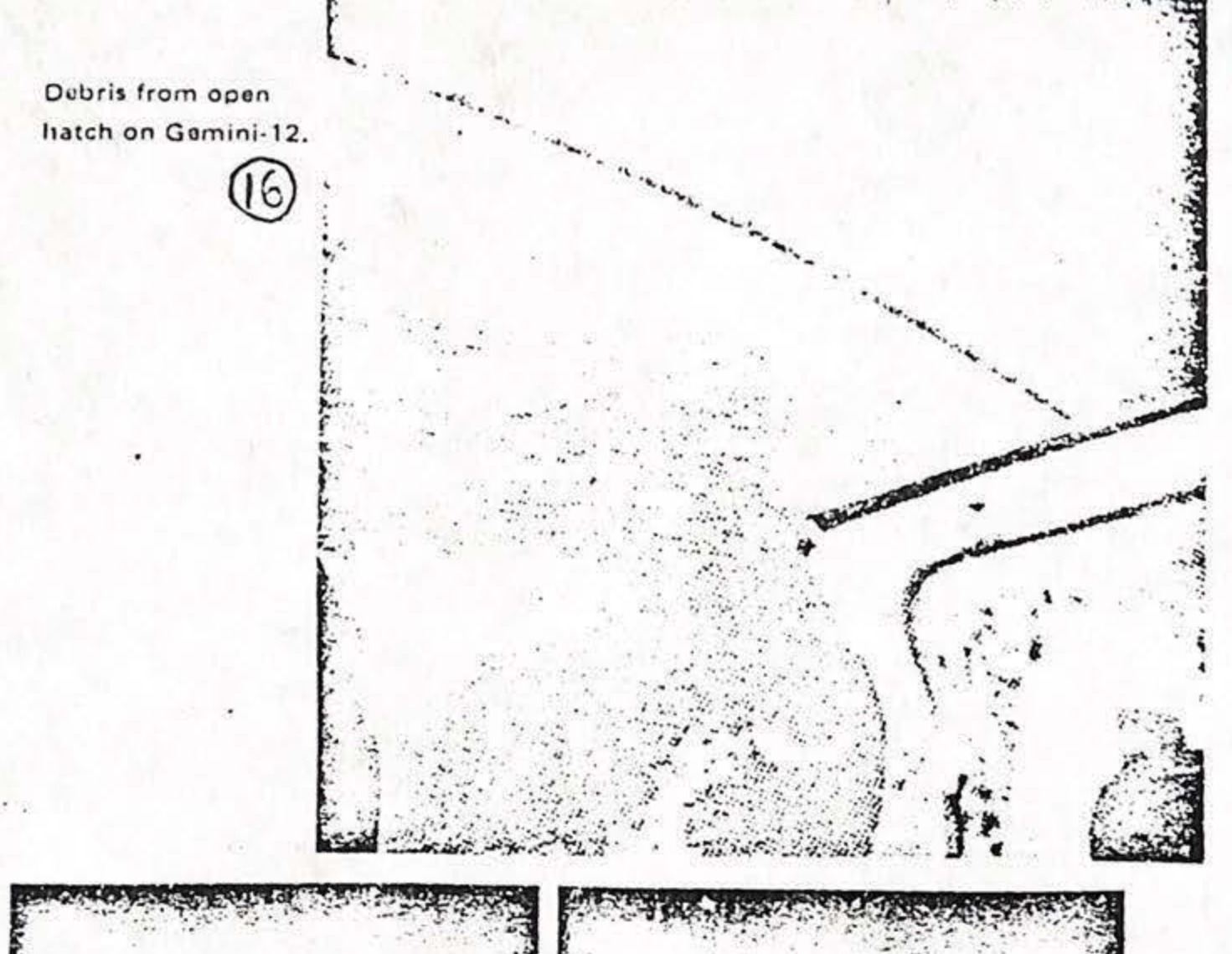
Debris from open hatch on Gemini-12.
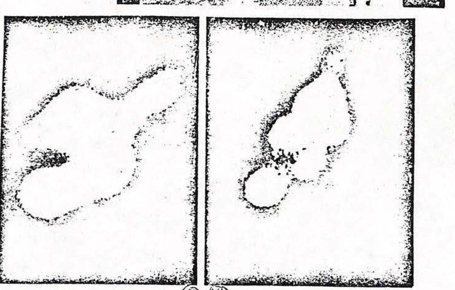
Blowups of Gemini-11 photos of Proton-3. Sun glare and extreme magnification contribute to bizarre appearance.
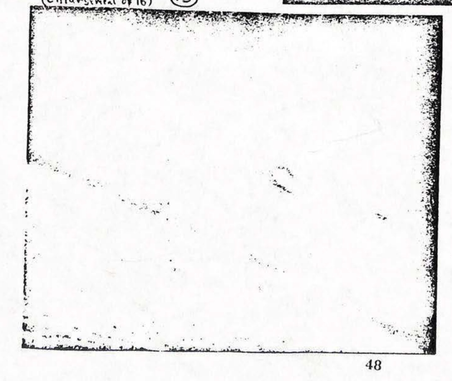
Fragment in focus at range of 3 to 5 feet-Sandler calls it "unidentifiable", and Mallan and Barry also use it. (enlargement of 16)
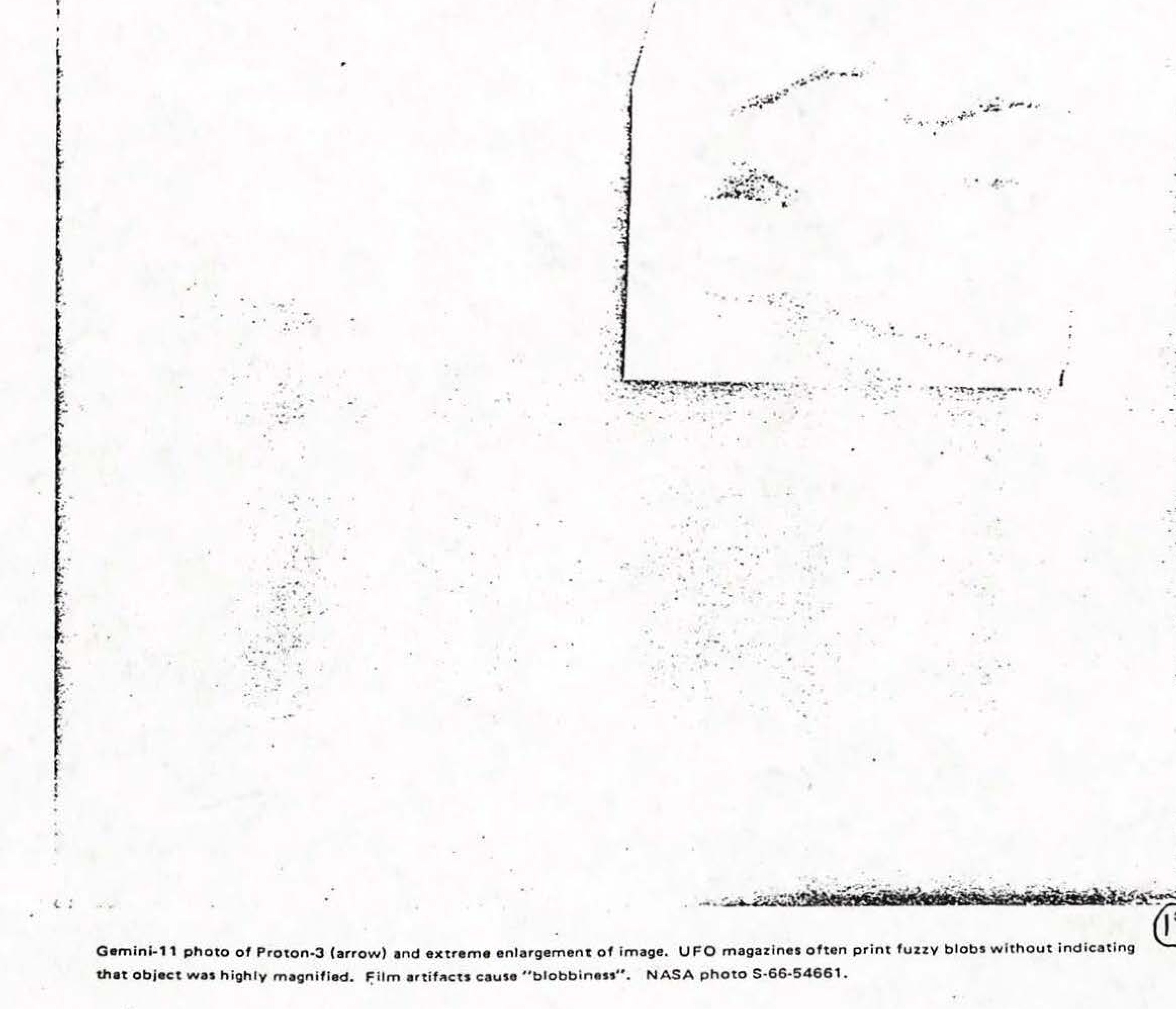
Gemini-11 photo of Proton-3 (arrow) and extreme enlargement of image. UFO magazines often print fuzzy blobs without indicating that object was highly magnified. Film artifacts cause "blobbiness". NASA photo S-66-54661.
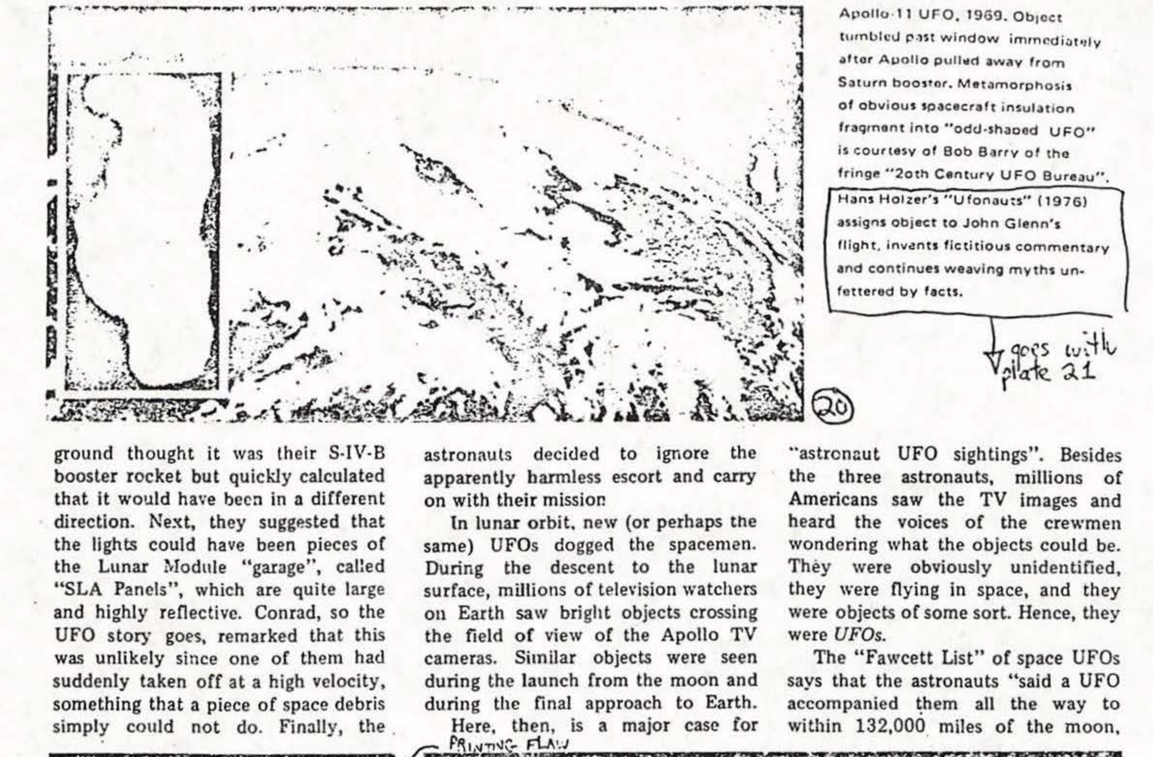
Apollo 11 UFO, 1969. Object tumbled past window immediately after Apollo pulled away from Saturn booster. Metamorphosis of obvious spacecraft insulation fragment into "odd-shaped UFO" is courtesy of Bob Barry of the fringe "20th Century UFO Bureau". Hans Holzer's "Ufonauts" (1976) assigns object to John Glenn's flight, invents fictitious commentary and continues weaving myths unfettered by facts.
Mercury-7. "Domed UFO" on Scott Carpenter's flight in 1963. Smears and glares change from one frame to the next while astronaut was snapping pictures of limp balloon sub-satellite. see plates 2,3,4,5
Two objects drifting out of open hatch (lower right) of Gemini-12. Both specks are out of focus and hence are within several feet of camera. -which had a very large depth of field. Object on right, in focus, is a scrap of paper. NASA photo S-66-62871.
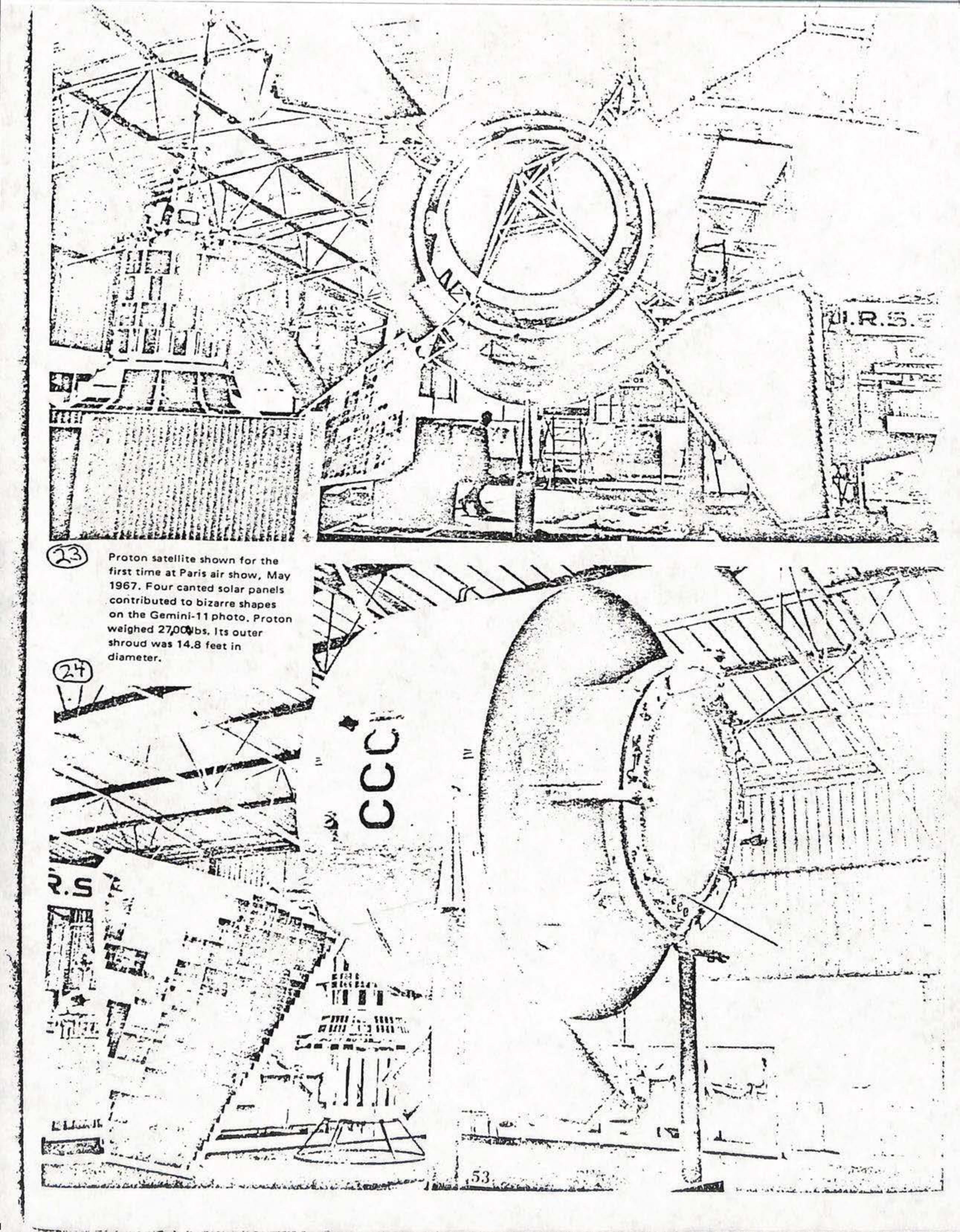
Proton satellite shown for the first time at Paris air show, May 1967. Four canted solar panels contributed to bizarre shapes on the Gemini-11 photo. Proton weighed 27,00 lbs. Its outer shroud was 14.8 feet in diameter.
Published newspaper story on UFSs captions this photo: "These two UFOs were photographed on July 19, 1969-the day before Apollo's historic moon landing-- during Buzz Aldrin's scheduled lunar photo session. Note the similarity to the shot snapped three years earlier during Gemini-12."
This photo was snapped only moments after Aldrin's other Apollo 11 shot. Here the two UFOs have begun their separation and a halo-like force field between the two is clearly shown.
Gemini-7 photo of sunlight glinting off roll thruster rockets on nose. Photo forgers airbrushed the nose/Earth boundary out, making the two lights appear to be floating in space. NASAphoto S65-63722.
NASA photo (right) SL3-118-2140 and variations (above and below) as published with erroneous captions.
Shot during Sky Lab III second manned Sky Lab Flight 263 day of 1973-1645 Zulu Time. NASA Photo SL3-118-2140 (4 shots taken) Listed as unidentified object or satellite by NASA Photo Evaluation Lab.
Another variation of the Skylab photo.
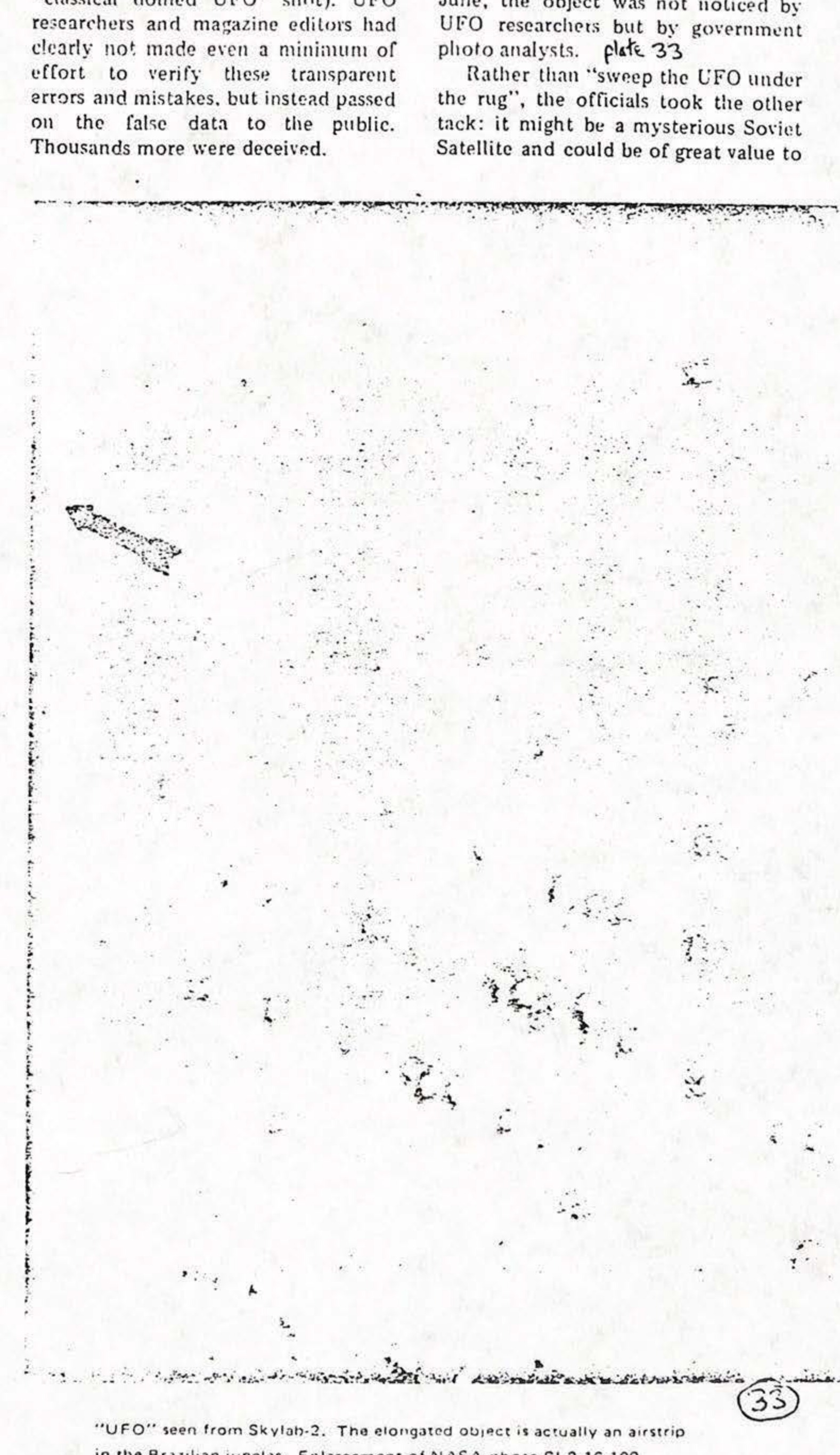
"UFO" seen from Skylab-2. The elongated object is actually an airstrip in the Brazilian jungles. Enlargement of NASA photo SL2-16-109.
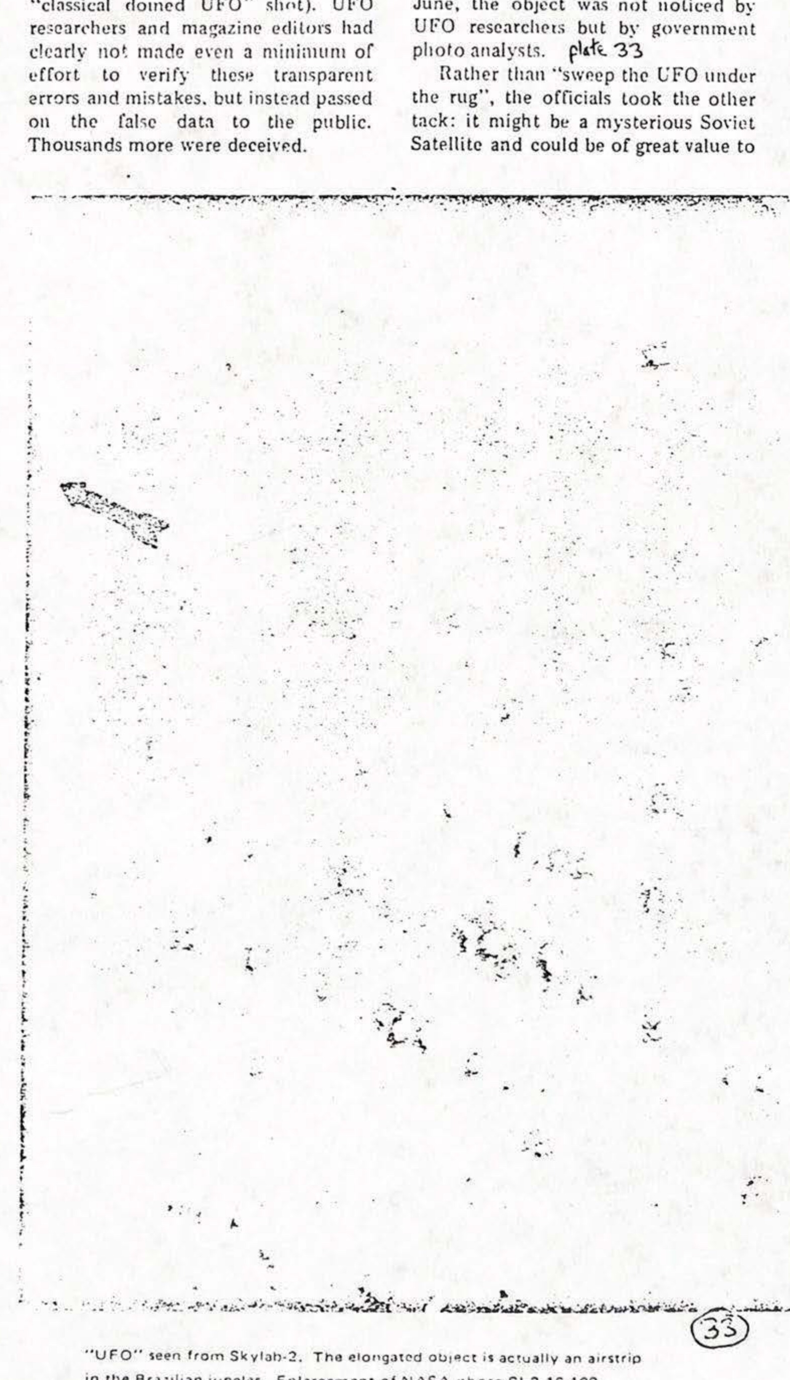
"UFO" seen from Skylab-2. The elongated object is actually an airstrip in the Brazilian jungles. Enlargement of NASA photo SL2-16-109.
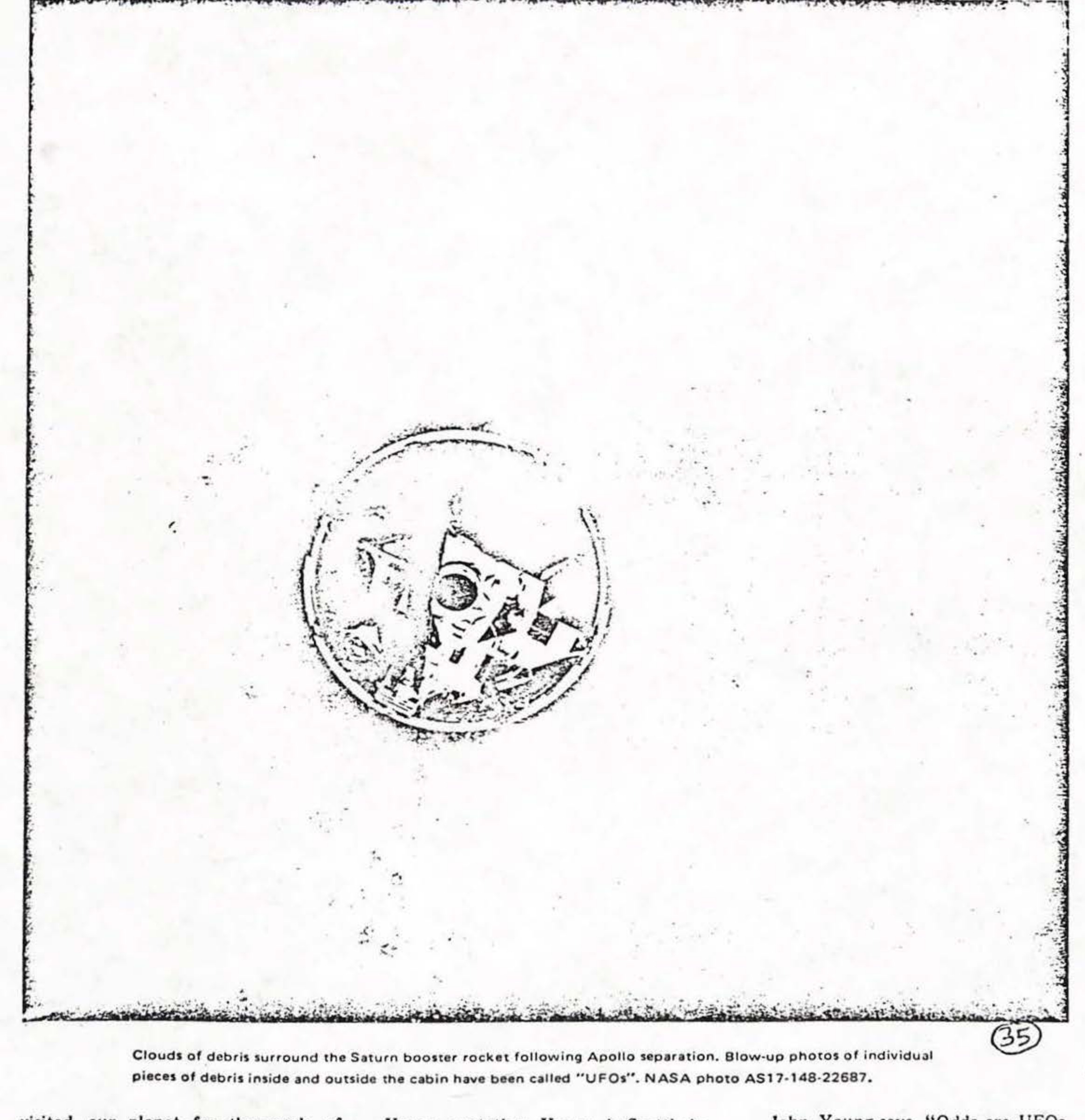
Clouds of debris surround the Saturn booster rocket following Apollo separation. Blow-up photos of individual pieces of debris inside and outside the cabin have been called "UFOs". NASA photo AS17-148-22687.
A common source of space and other UFOs is shown here. The aura and the lens-shaped disc is actually a sunrise photographed from Skylab. NASA photo SL3-118-2177.
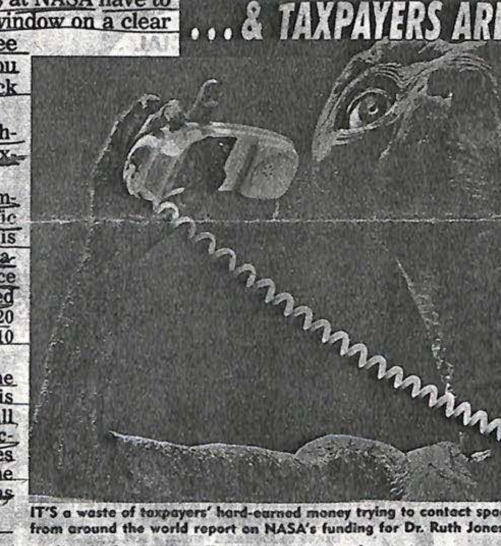
A person on a telephone.
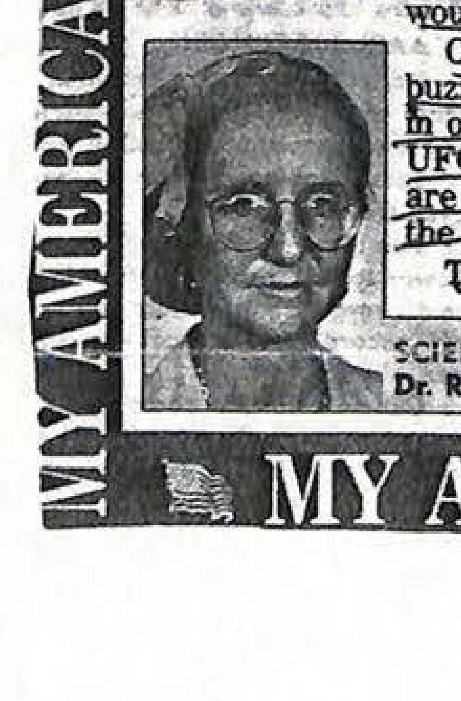
Inset photo of Dr. Ruth Jones Hamer.
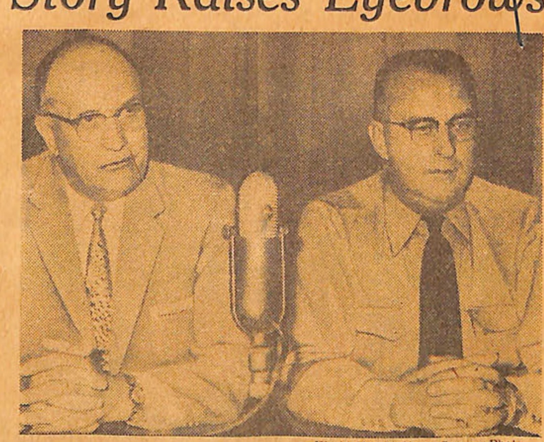
-World-Herald News Service Photo. Schmidt (left) and Kearney Police Chief Nelson... In "heart-to-heart" talk.
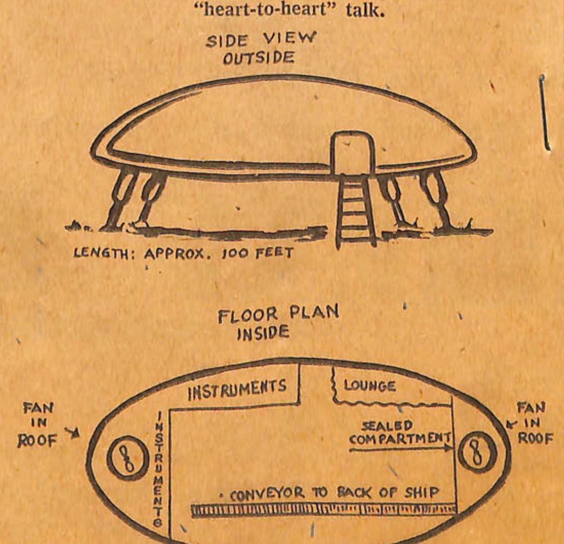
SIDE VIEW OUTSIDE LENGTH: APPROX. 100 FEET FLOOR PLAN INSIDE INSTRUMENTS LOUNGE SEALED COMPARTMENT FAN IN ROOF FAN IN ROOF CONVEYOR TO BACK OF SHIP The Schmidtnik... As described by the grain buyer.
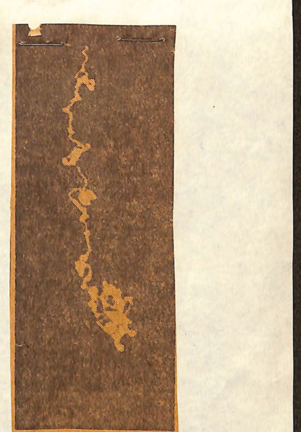
Associated Press J. G. Kirby of Dallas made this photo of a diamond shaped object flying through the sky while he and his family were driving near Amarillo, Tex., in August, 1956. The photo was turned over to the FBI and has just been released after intensive study. The Air Force described the glow as "radiation vapor."
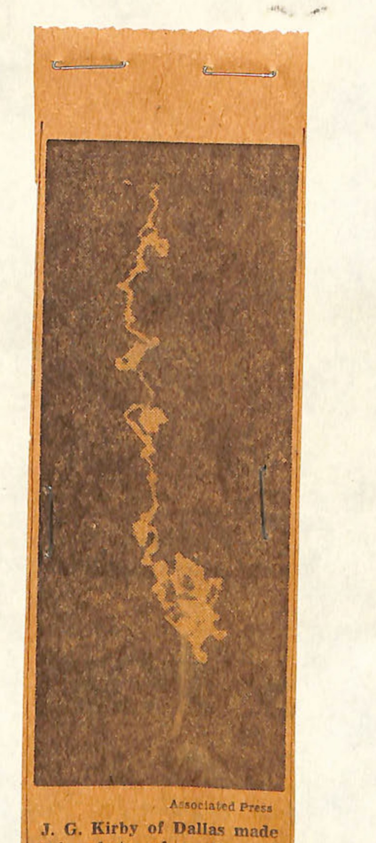
Associated Press J. G. Kirby of Dallas made this photo of a diamond shaped object flying through the sky while he and his family were driving near Amarillo, Tex., in August, 1956. The photo was turned over to the FBI and has just been released after intensive study. The Air Force described the glow as "radiation vapor."
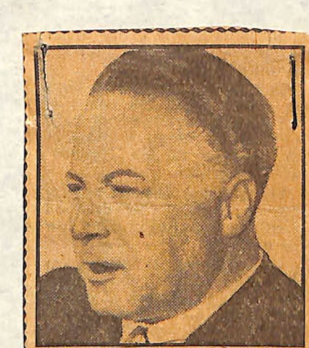
GEORG KLEIN
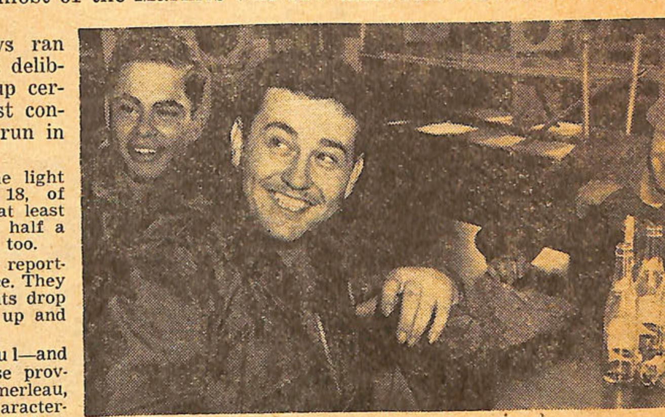
Photo of three men, one smiling prominently in the center.
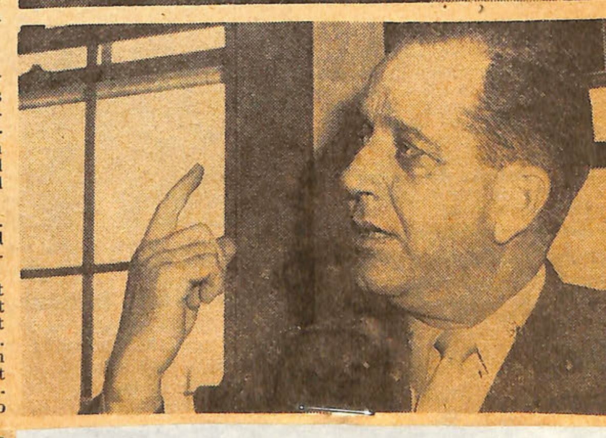
Photo of a man pointing.
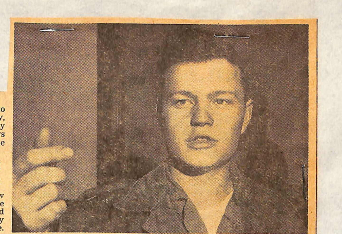
Pfc. Bennett (top front) grabbed a butcher knife and said: "It's landing in the tank shed!" Maj. Pomerleau (middle photo) is skeptical, but still curious. Pfc. Viets (bottom photo) saw enough to convince him "that was no airplane." -News Staff Photos by Gene Thomas
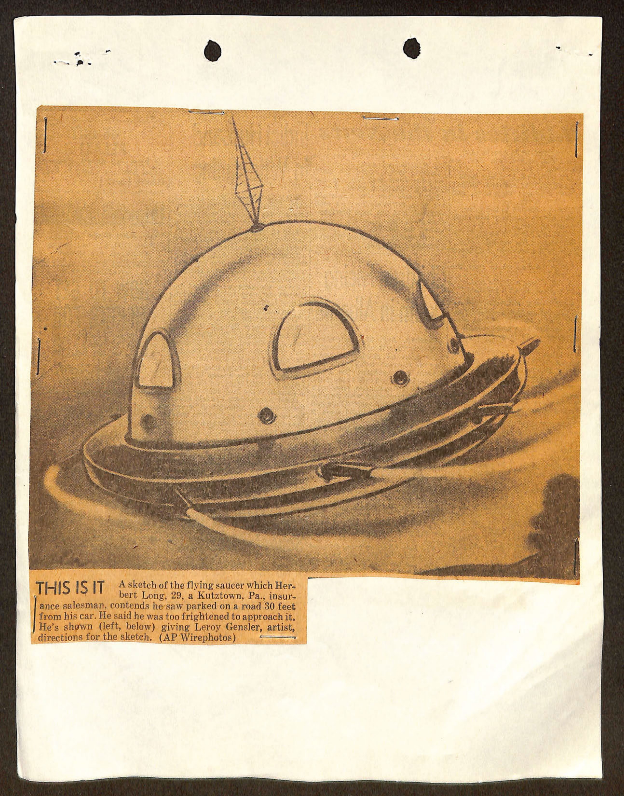
A sketch of the flying saucer which Herbert Long, 29, a Kutztown, Pa., insurance salesman, contends he saw parked on a road 30 feet from his car. He said he was too frightened to approach it. He's shown (left, below) giving Leroy Gensler, artist, directions for the sketch. (AP Wirephotos)
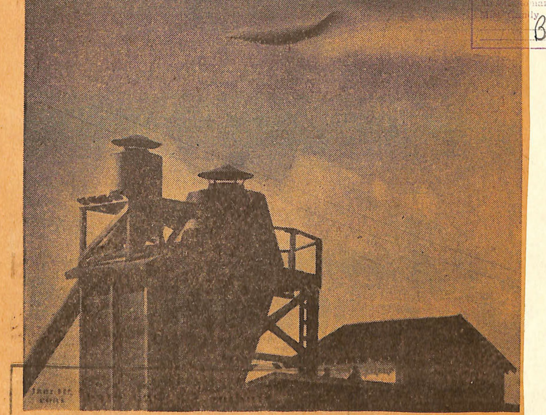
FLYING SAUCER MAYBE?-The unknown object over the building in the picture, photographed above Anacortes, moves swiftly through the sky, seemingly a part of a cloud formation. But is it? Walter Elliott of Anacortes was preparing to take a picture of the building when he noticed the unusual saucer-like object in his view finder, so he snapped the picture at 1/100th of a second. Elliott was unable to determine the nature of the unusual object which quickly disappeared. (Associated Press Wirephoto.)
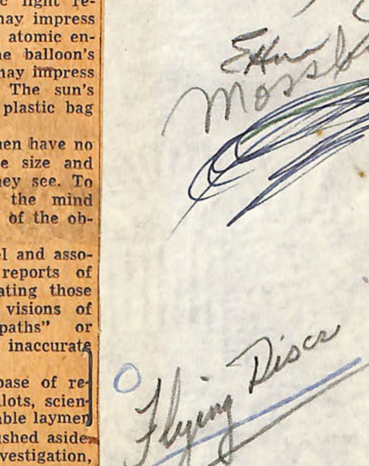
Hand-drawn sketch of flying saucer or balloon-like object
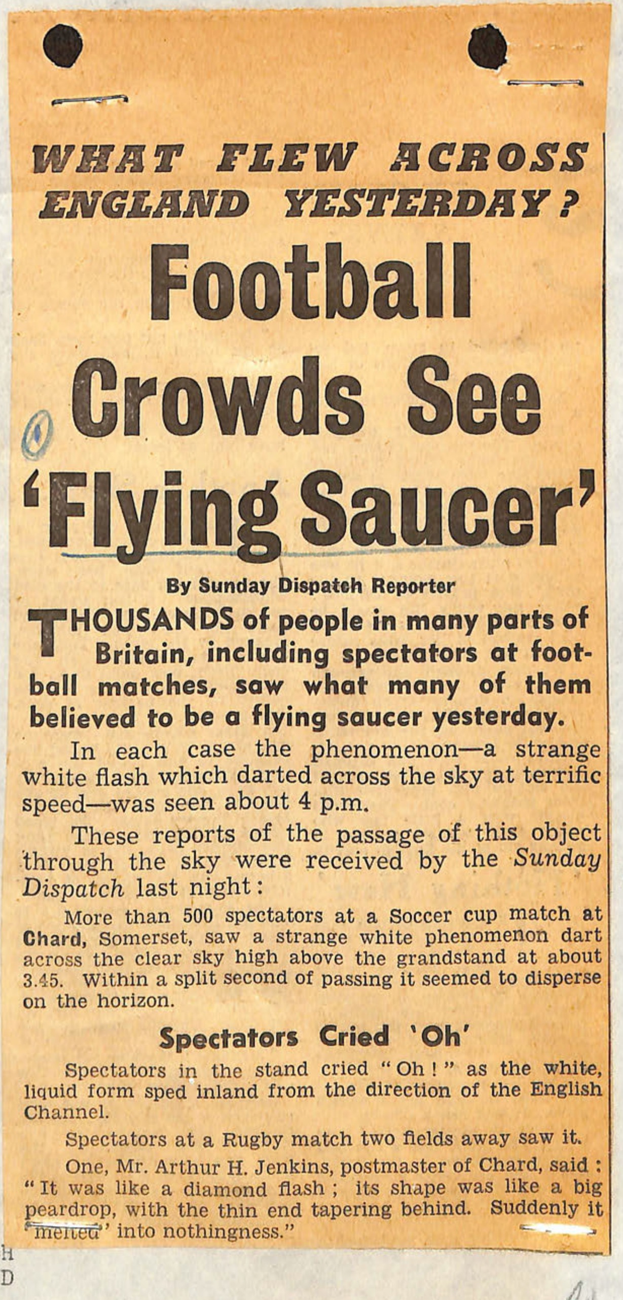
Newspaper clipping from Sunday Dispatch about flying saucer sightings over England
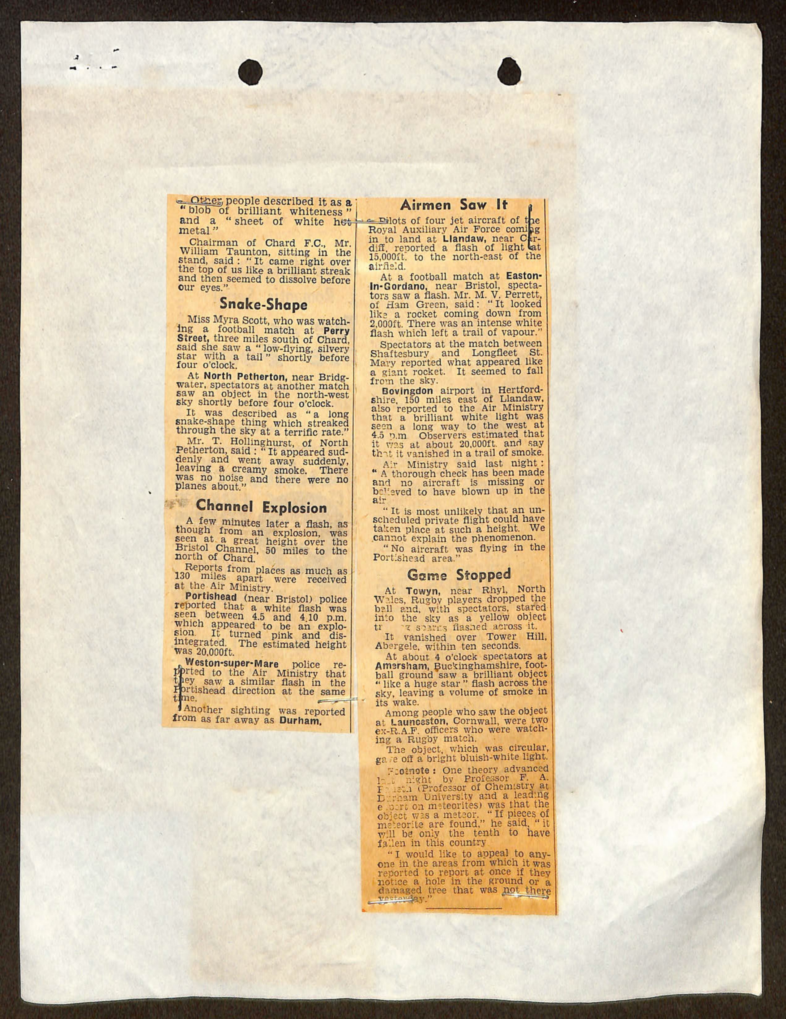
Newspaper clipping describing multiple UFO sightings across England and Wales, including reports from airmen, football spectators, and Air Ministry officials
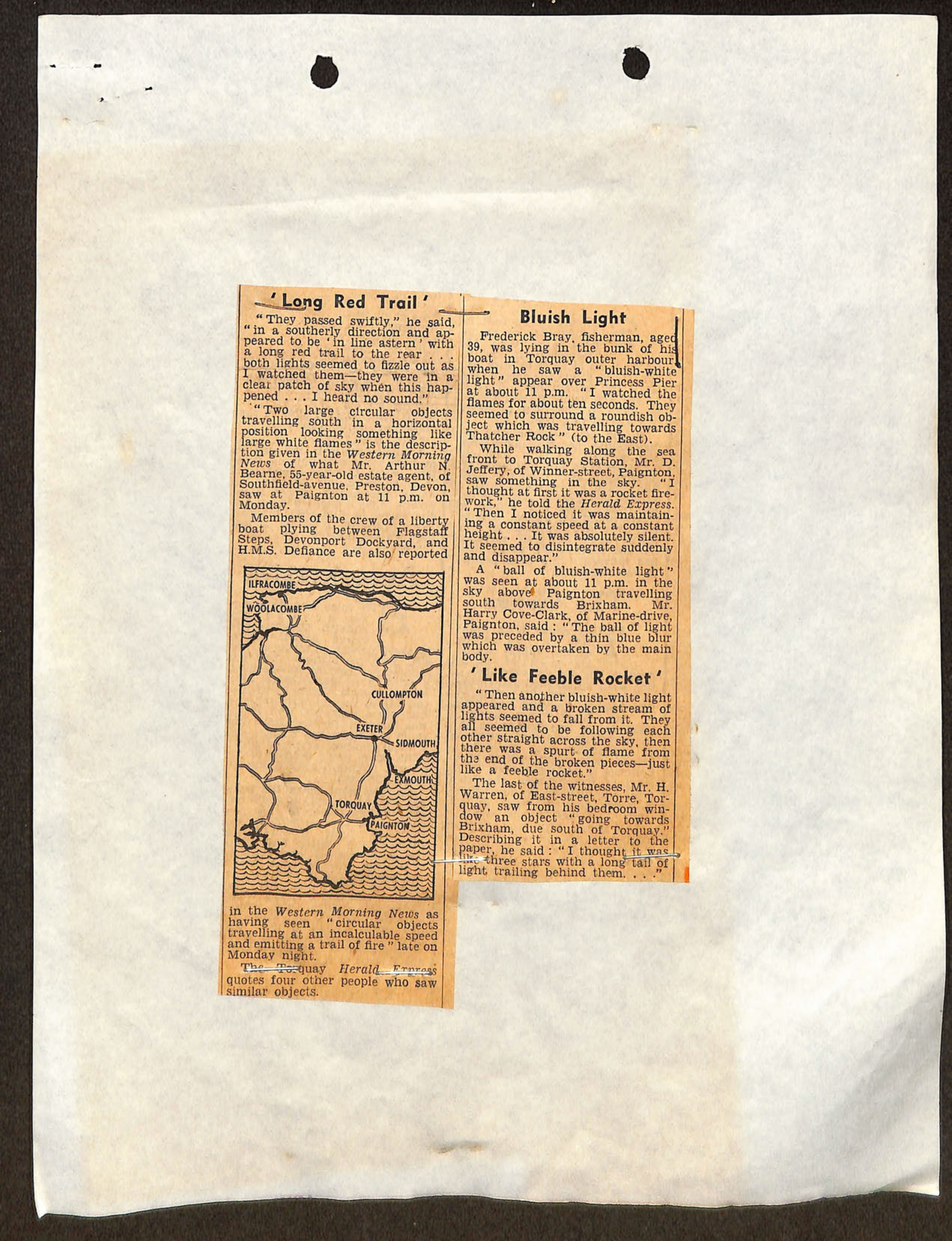
Newspaper clipping with map of Devon coast showing sighting locations and multiple witness accounts of UFO sightings
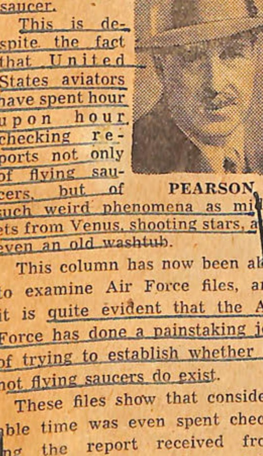
Portrait photograph of Drew Pearson
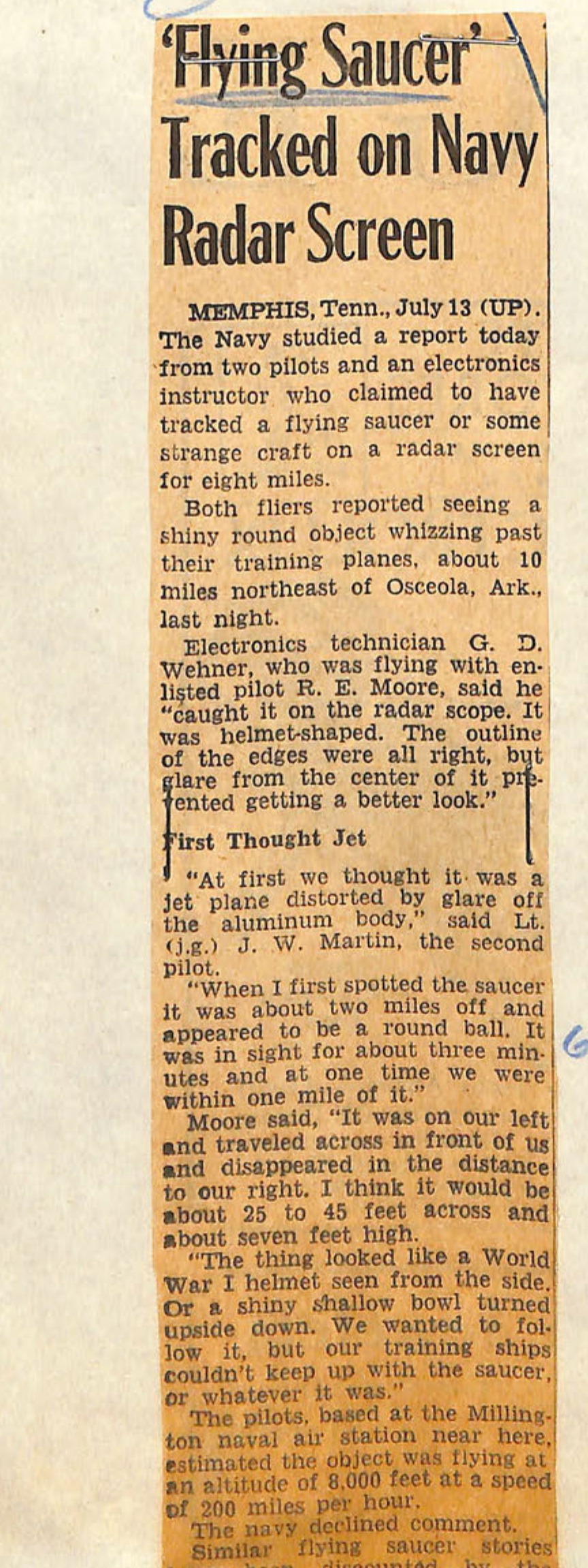
Newspaper clipping about flying saucer tracked on Navy radar screen
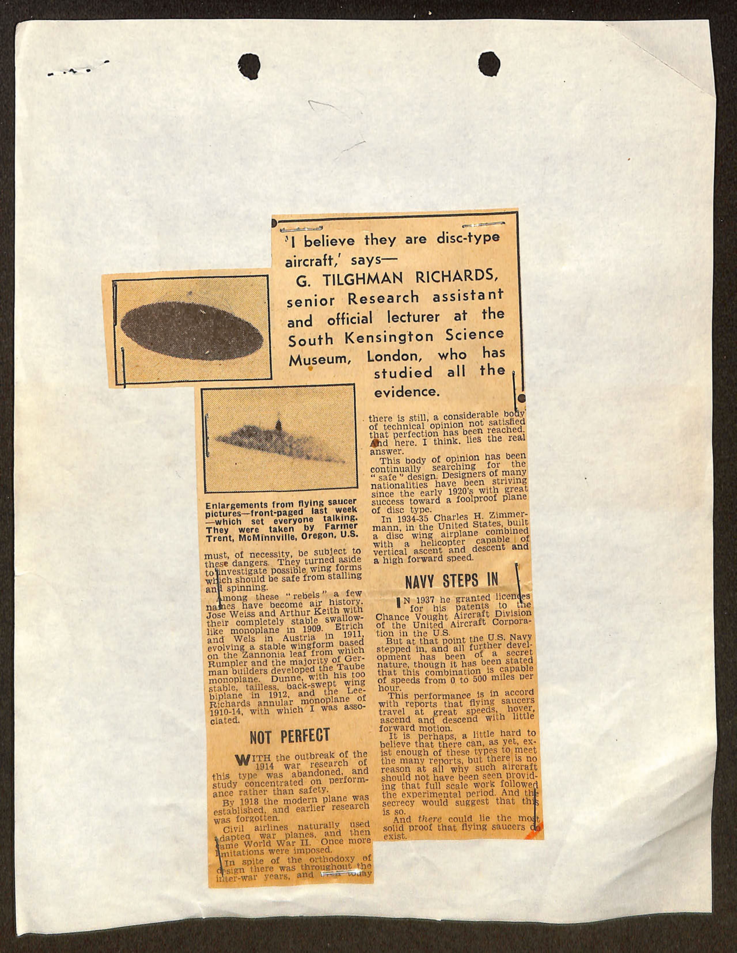
Newspaper clipping with two flying saucer photographs and article by G. Tilghman Richards discussing disc-type aircraft development and Navy involvement
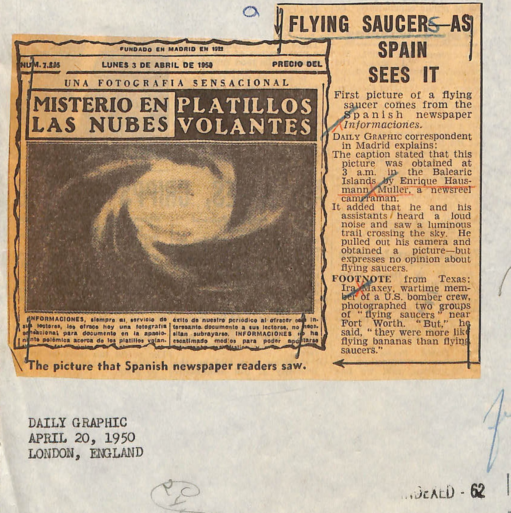
Spanish newspaper clipping showing alleged flying saucer photograph from Balearic Islands with headline 'MISTERIO EN LAS NUBES PLATILLOS VOLANTES' and English translation article
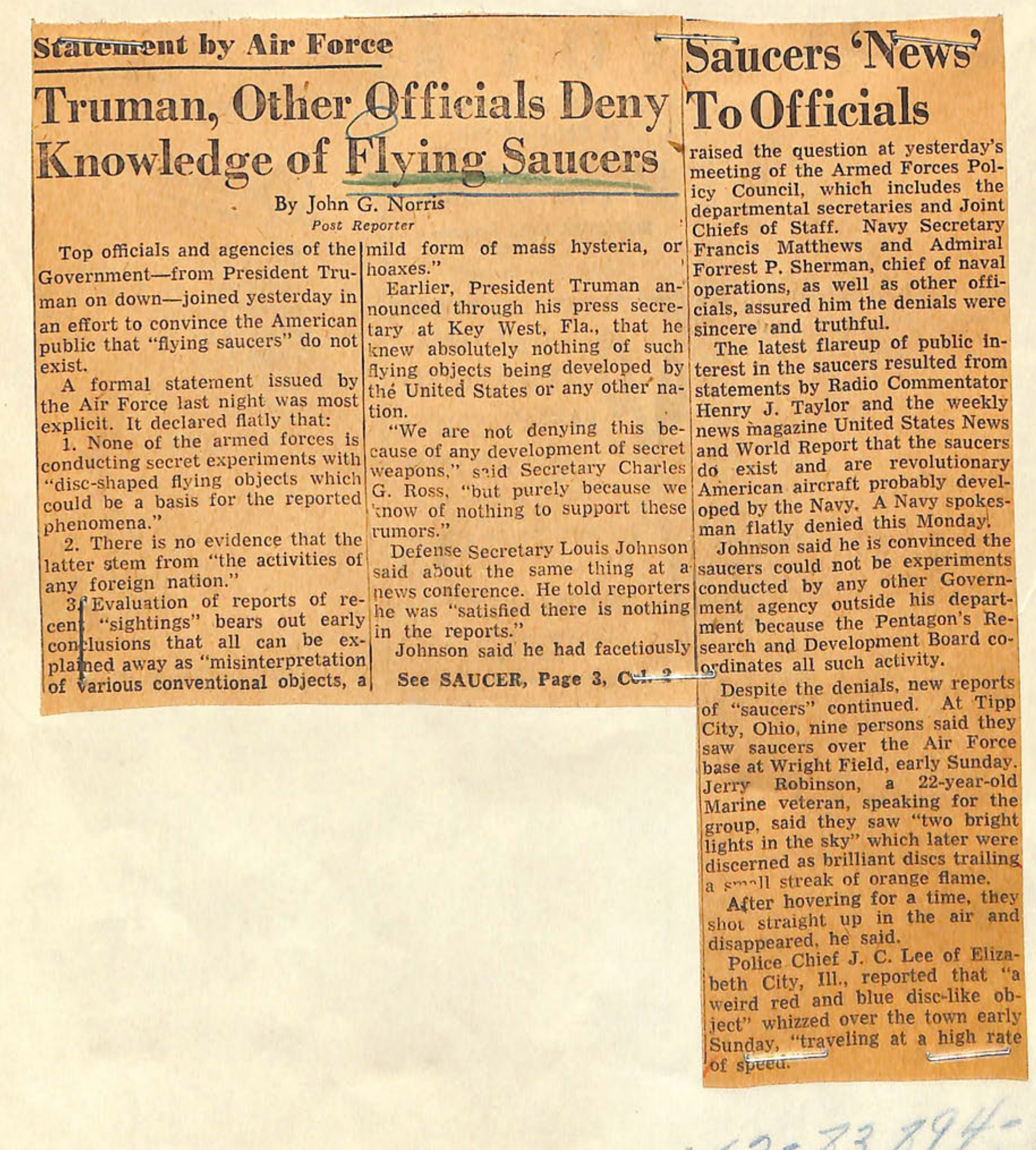
Newspaper clipping from Star Staff Reporter about flying saucer denials by Truman and other officials
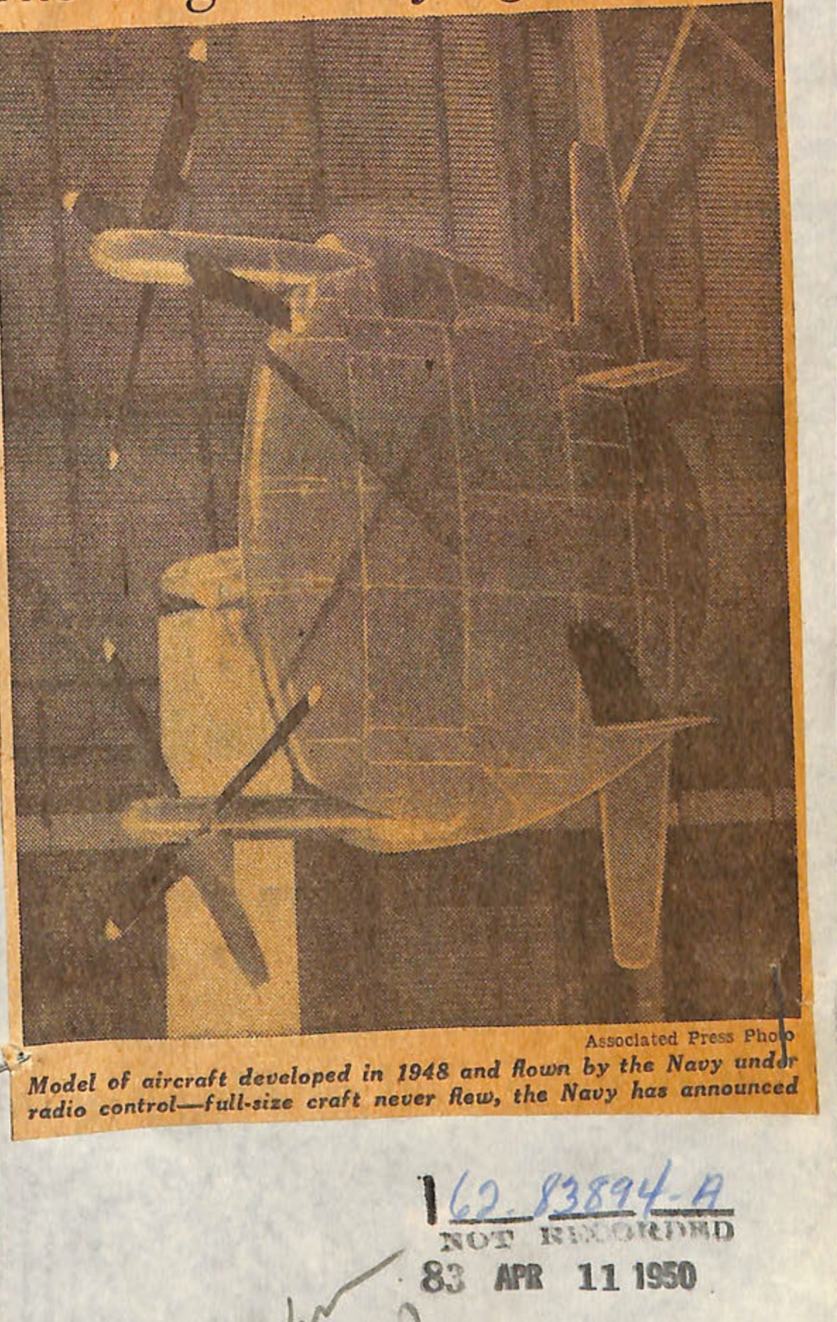
Model of aircraft developed in 1946 and flown by the Navy for radio control—full-size craft never flew, the Navy has announced
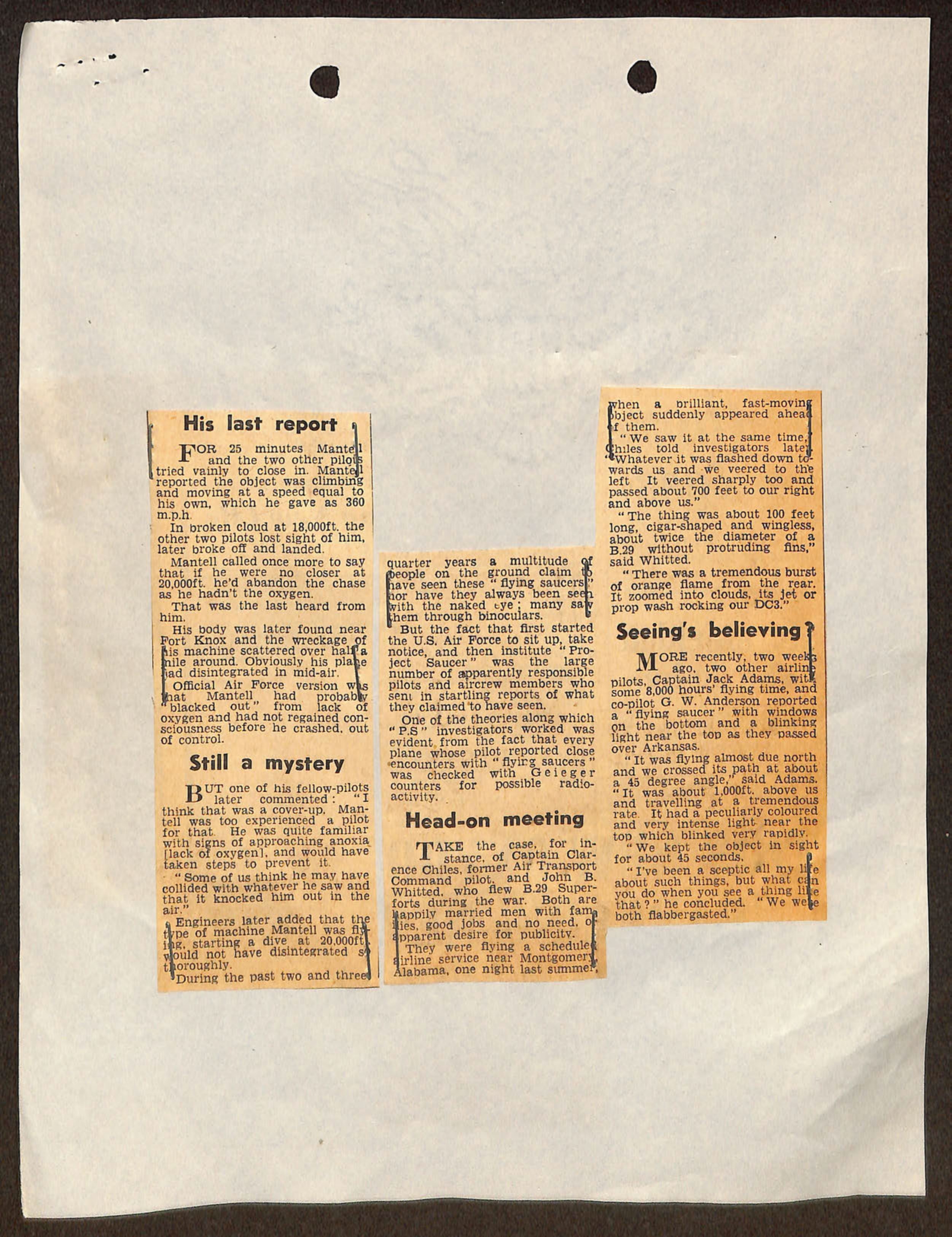
Newspaper clippings about UFO sightings including Mantell incident and pilot testimonies
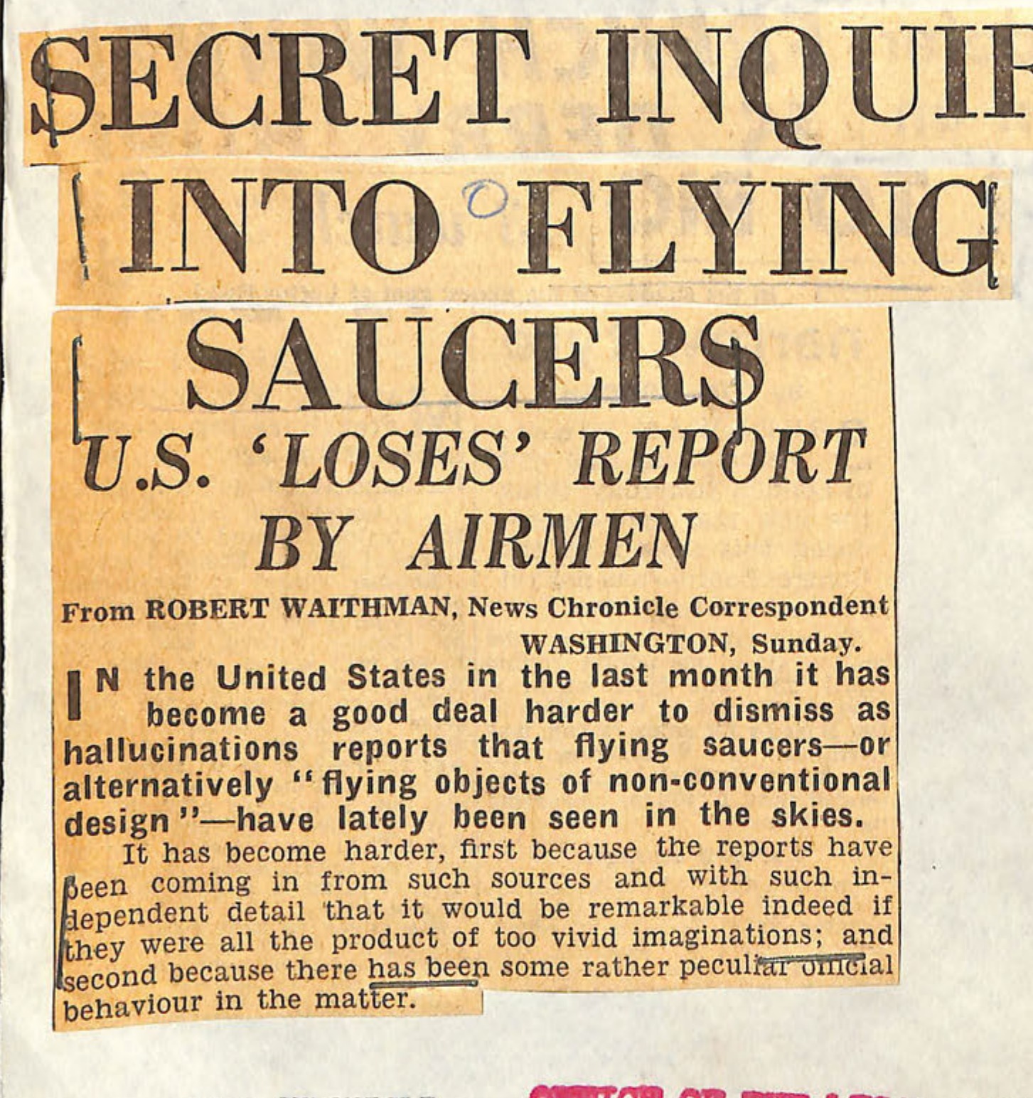
Newspaper clipping showing headline and article about flying saucers inquiry
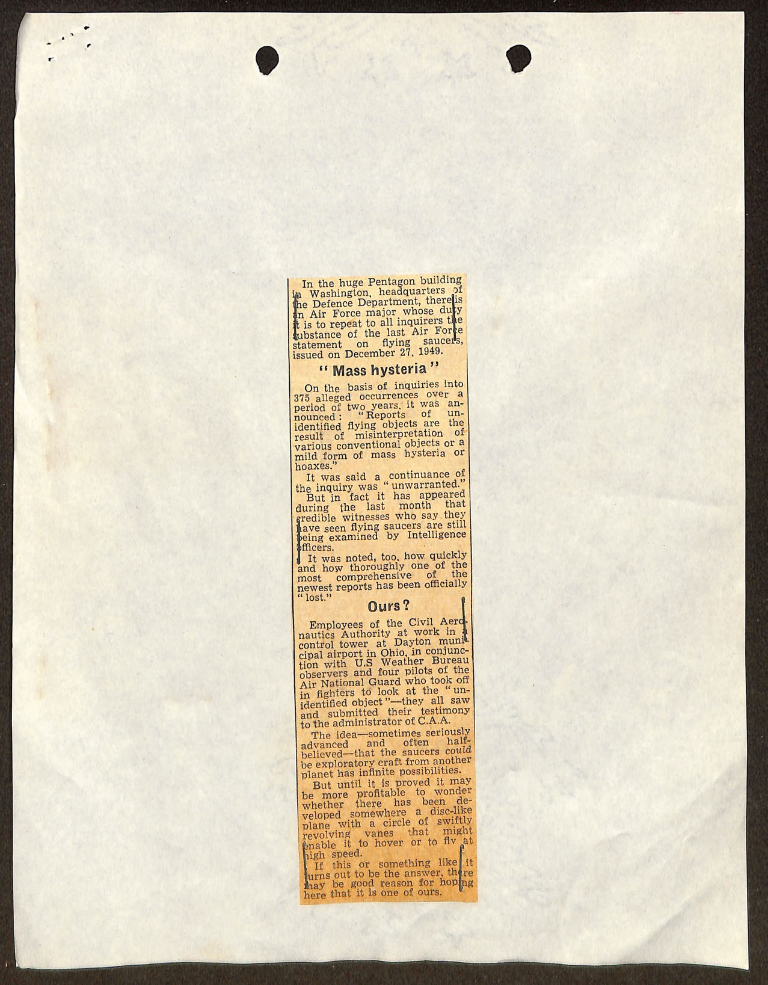
Newspaper clipping discussing Pentagon statement on flying saucers and mass hysteria, dated December 27, 1949
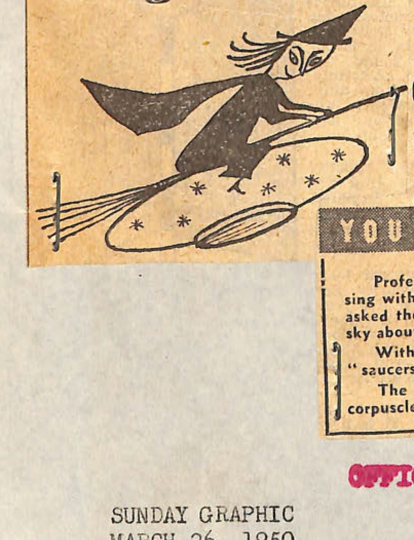
Illustration of flying saucer with cartoon figure riding it
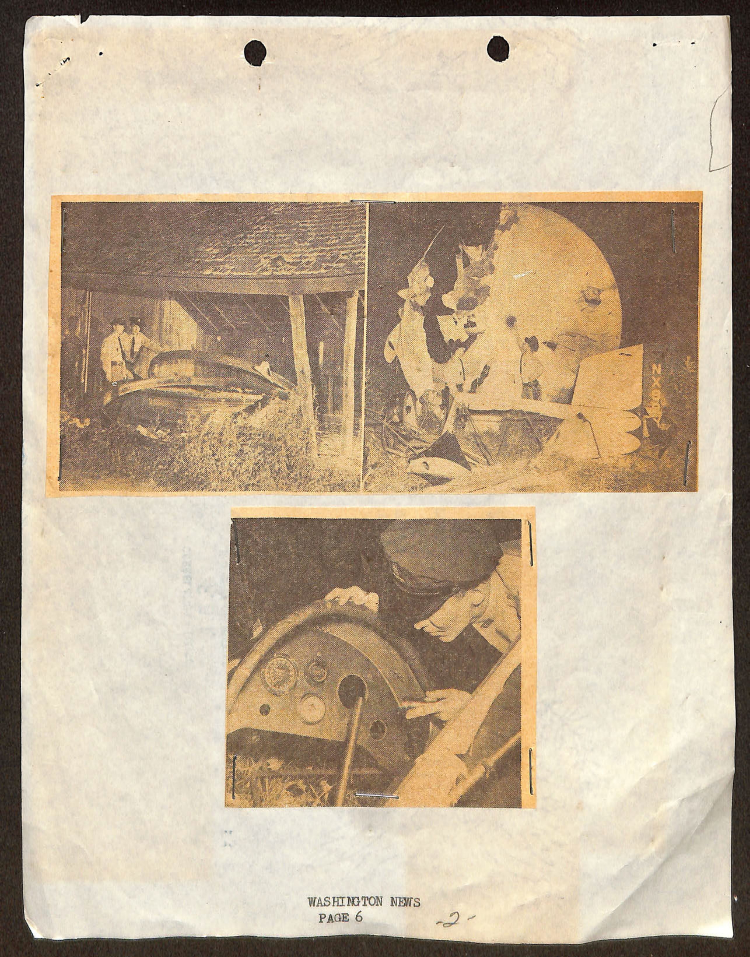
Three photographs of Jonathan E. Caldwell's experimental aircraft found in a barn near Glen Burnie, Md.
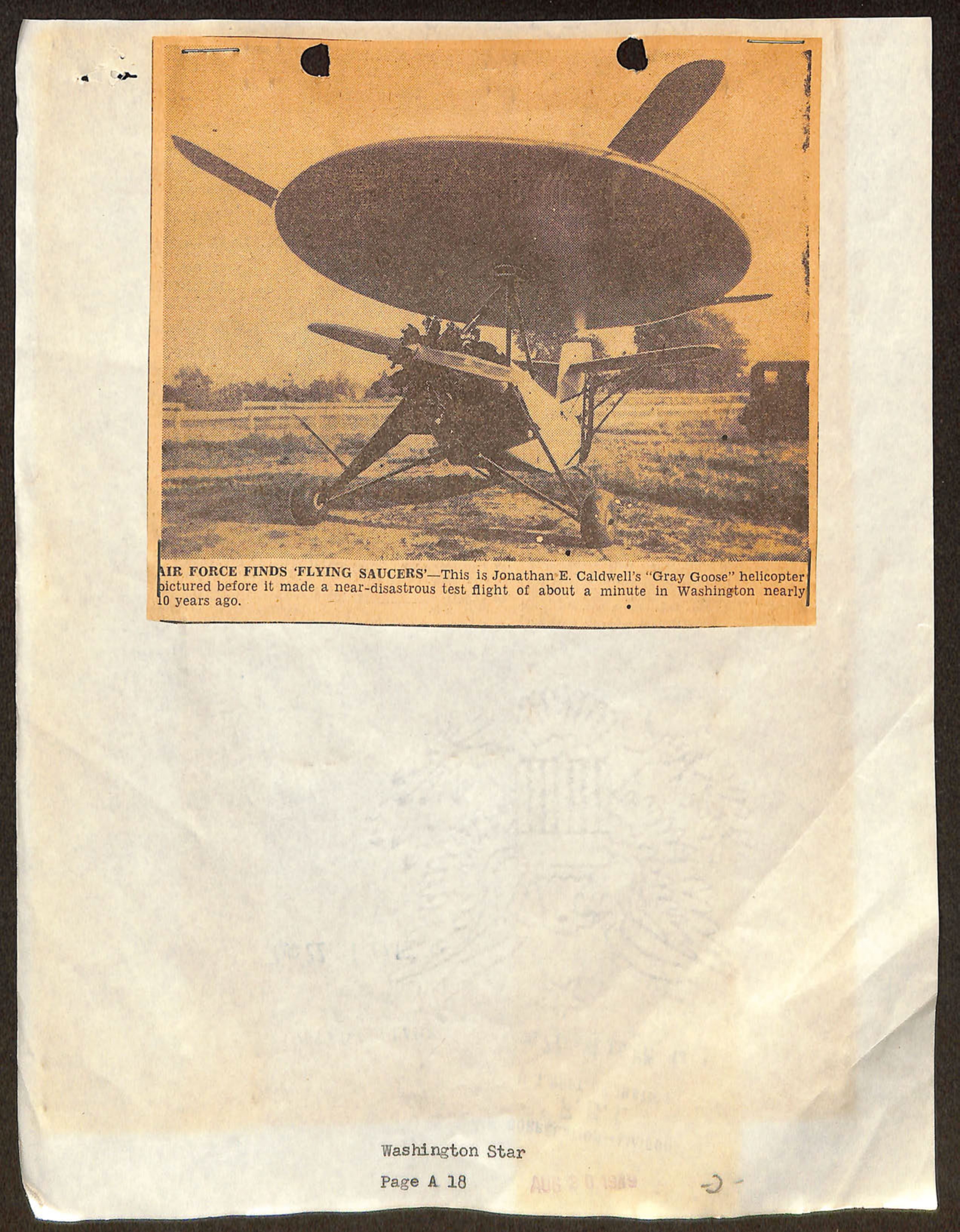
AIR FORCE FINDS 'FLYING SAUCERS' - This is Jonathan E. Caldwell's "Gray Goose" helicopter pictured before it made a near-disastrous test flight of about a minute in Washington nearly 10 years ago.
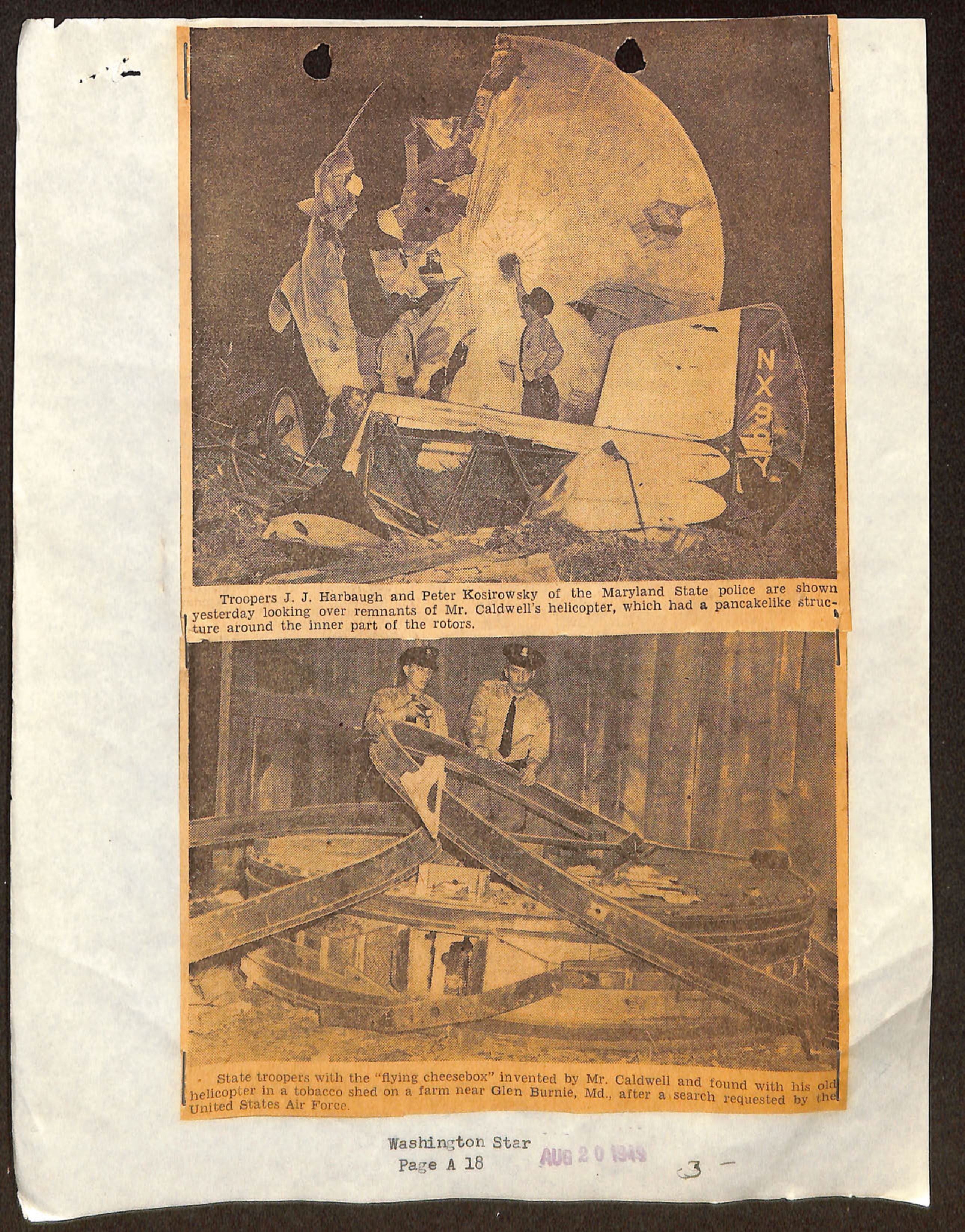
Photos of Maryland State police with remnants of Mr. Caldwell's helicopter and 'flying cheesebox' near Glen Burnie, Md.
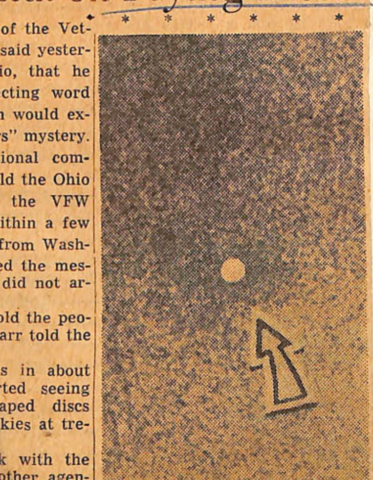
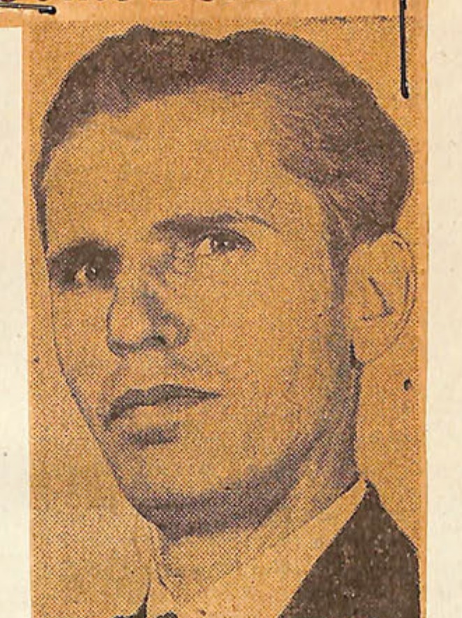
IS IT? Coast Guardsman Frank Ryman, 27, made this picture with a Speed Graphic camera from the front porch of his Seattle, Wash., residence. It shows, says Ryan, a "white saucer" (arrow) that is neither an airplane, a cloud, nor a silver balloon. So, is it a "flapjack" or a saucer? Or maybe a bottle cap? Photo is enlarged about 20 times
Post Staff Photo DAVID ATAMIAN, of 5160 Shoemaker la., Friendship Heights, Md., said he sav three or four flying discs Friday about midnight
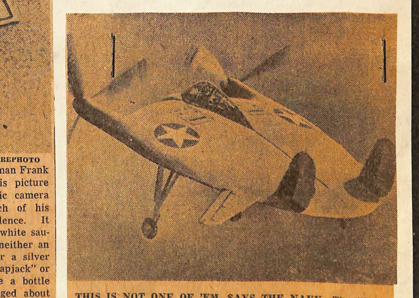
THIS IS NOT ONE OF 'EM, SAYS THE NAVY-The "flying pancake," a wingless plane developed by the Navy, is the only plane it has which might resemble the reported "flying say cers," but officials in Washington said yesterday that thi strange-looking aircraft has never left Bridgeport, Conn. Authorities are still skeptical that the mystery missiles said to has been seen in the skies over the West Coast and as far East as the Carolinas are any sort of new airplane
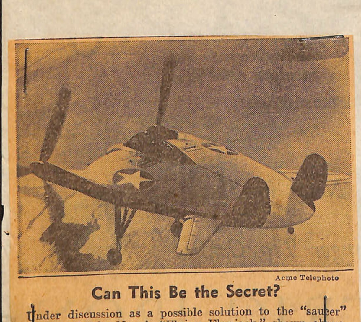
Acme Telephoto Can This Be the Secret? Under discussion as a possible solution to the "saucer" mystery is the Navy's "Flying Flapjack," shown above. Zipping along with its landing gear retracted, this plane would seem to be a supper plate spinning through the sky.
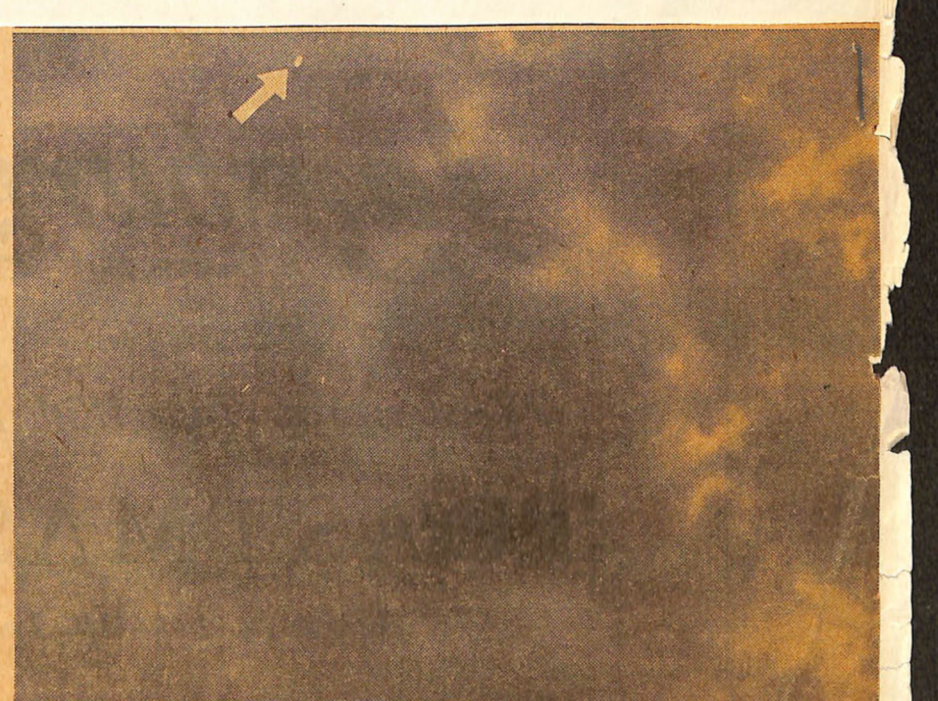
I.N.P. Photo by U.S. Coast Guard Is It Saucer, Sorcery, or Just Plain Sausage? Reports of "flying saucers" were laughed off by authorities until many witnesses, including reliable pilots and servicemen, said they had seen the plate-like objects whizzing overhead. Above is the picture Yeoman Frank Ryman, 27, took in the Seattle twilight when he observed what seemed to him to be a flying saucer 10,000 feet high traveling at 500 miles per hour.
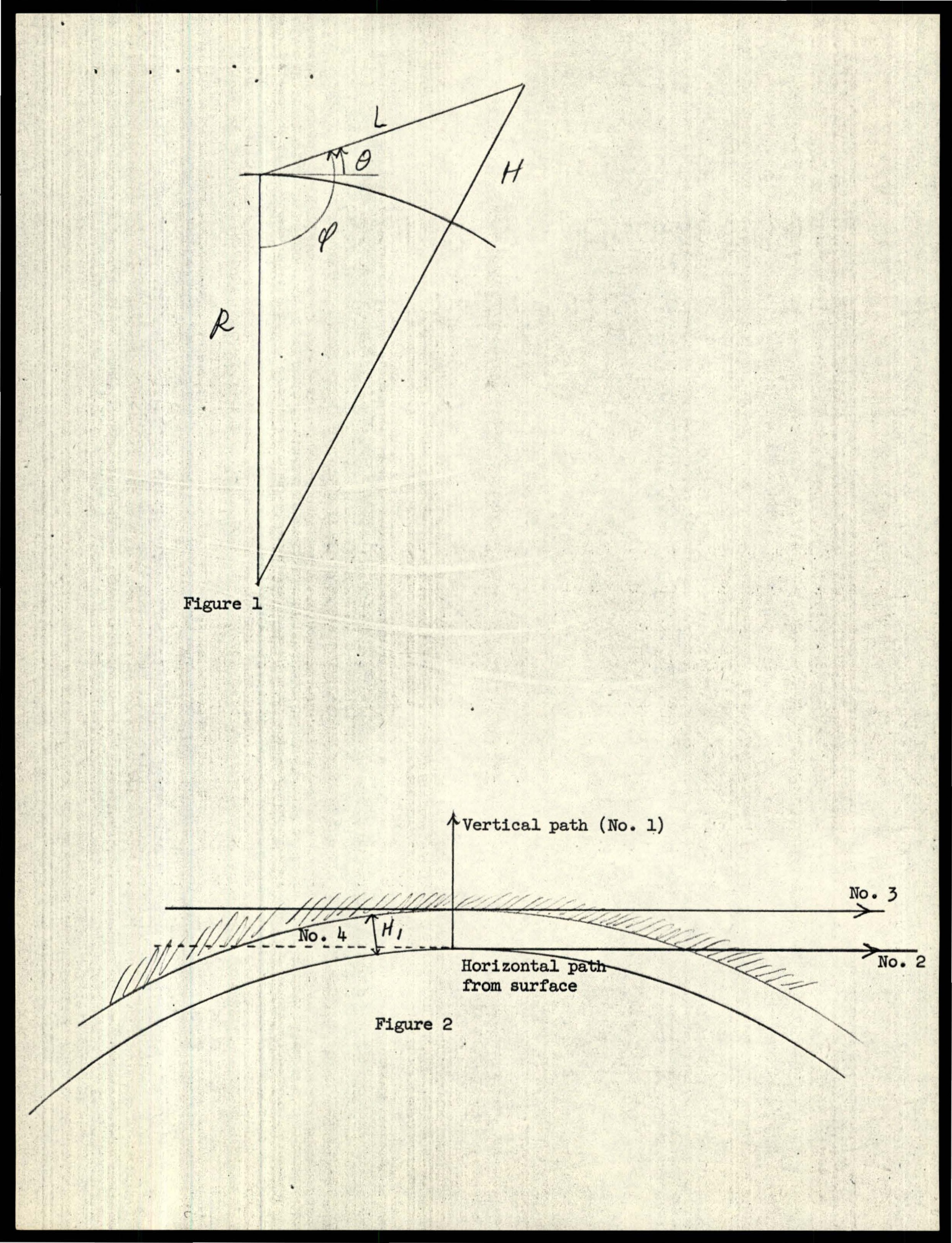
Figure 1 showing variables R, L, H, θ, φ.
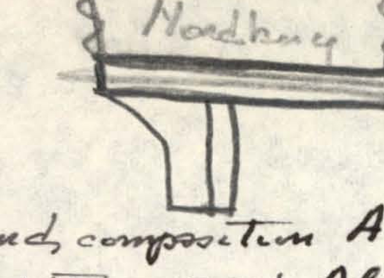
Small diagram labeled 'Nordberg'.
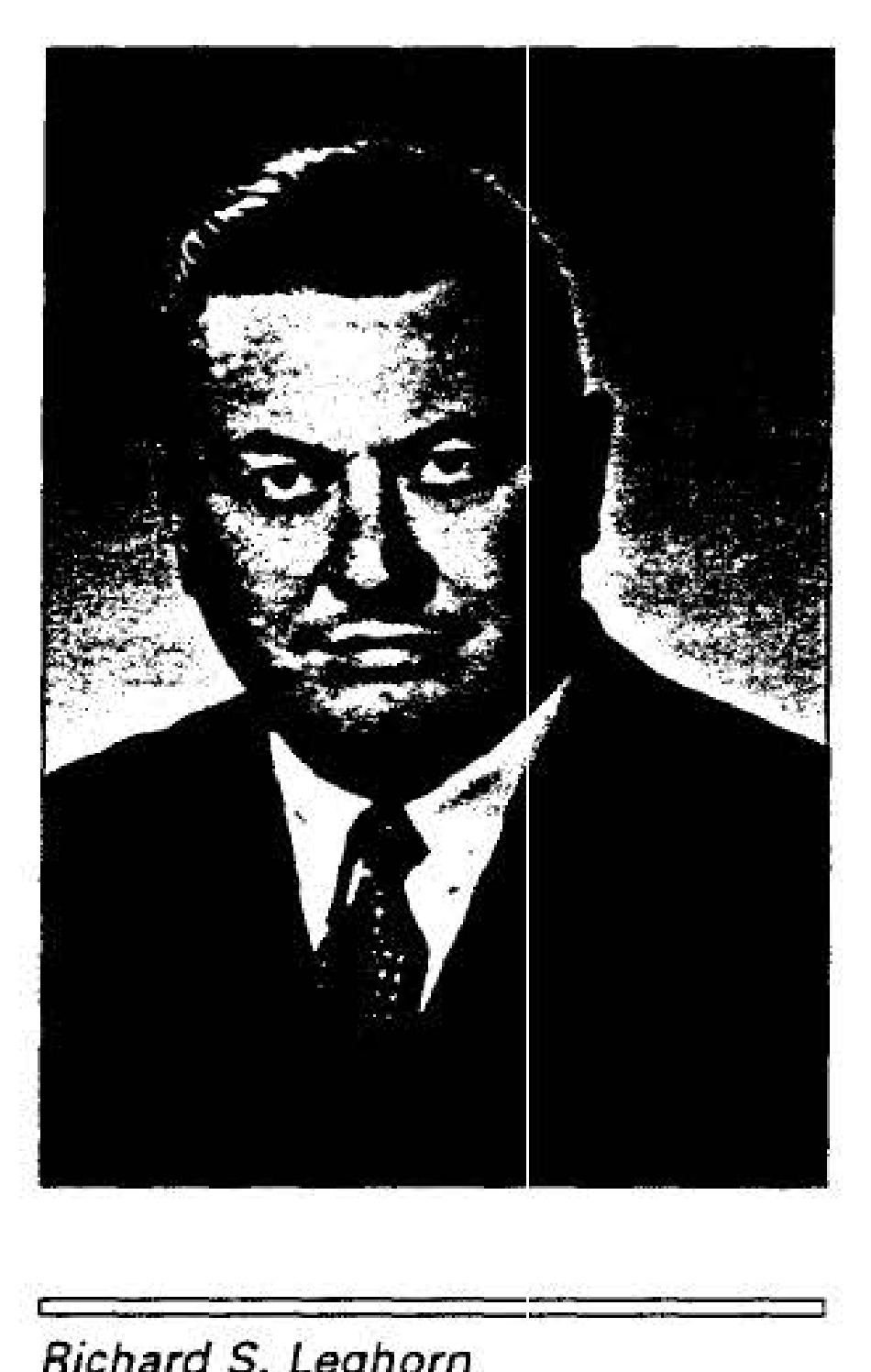
Richard S. Leghorn
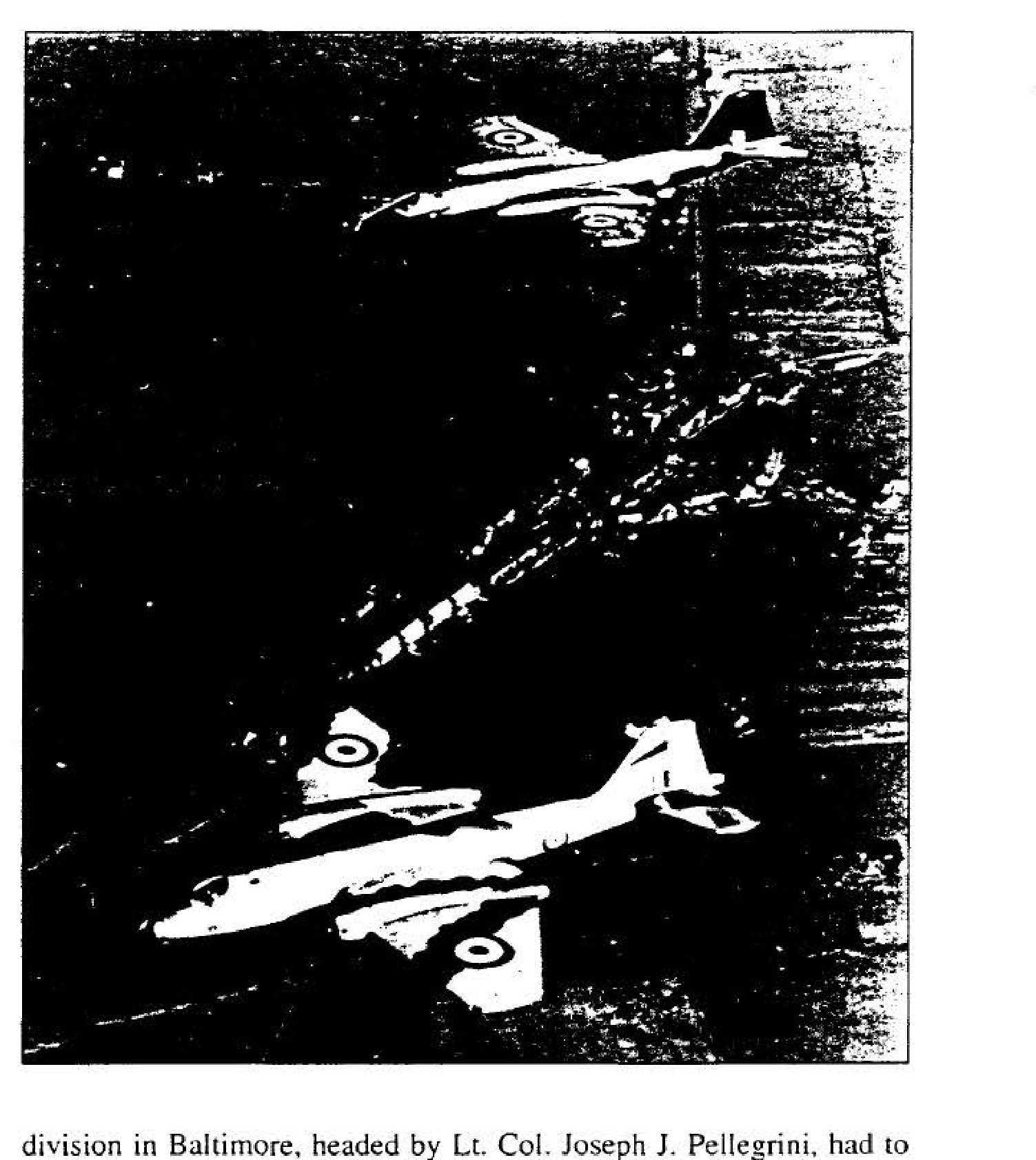
RAF Canberra Mark-PR3
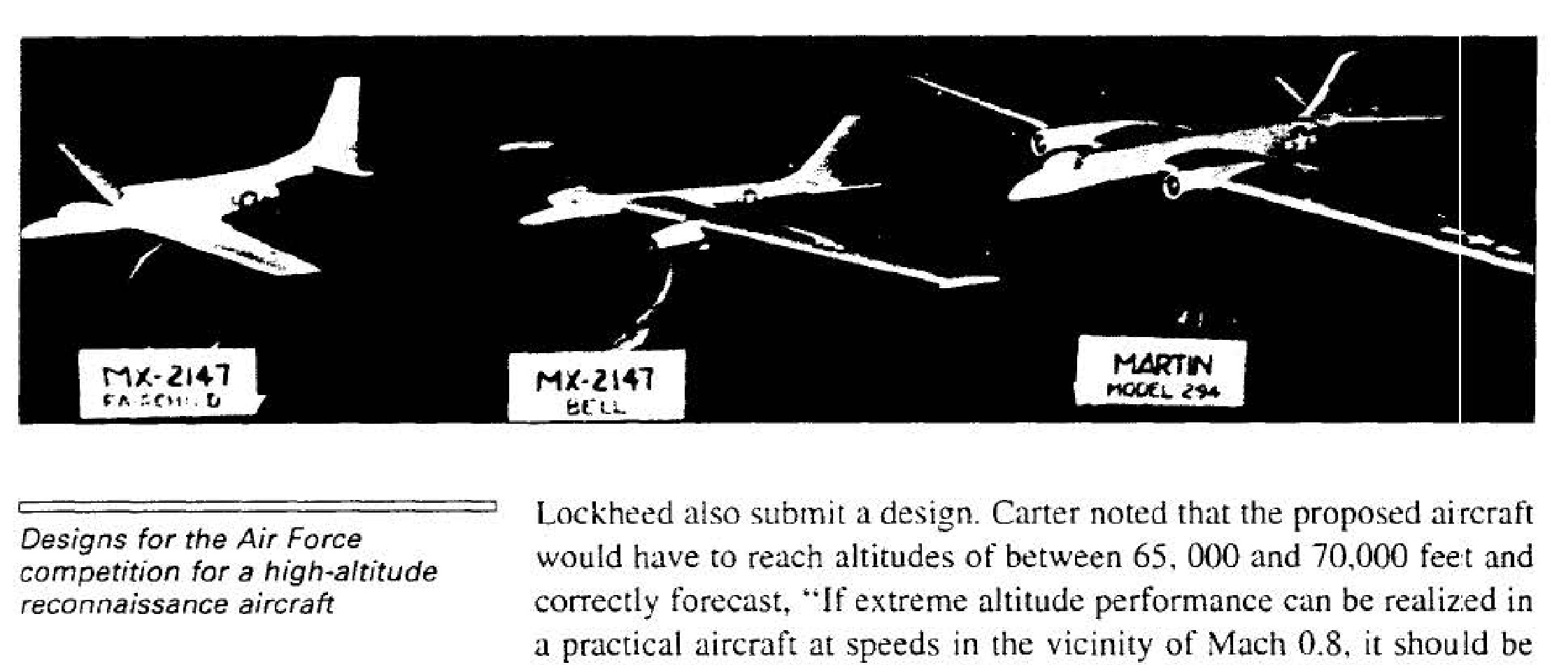
Designs for the Air Force competition for a high-altitude reconnaissance aircraft
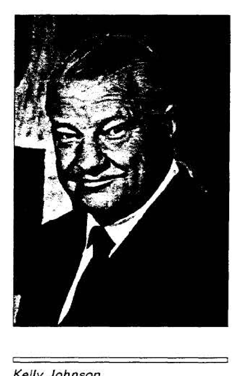
Kelly Johnson
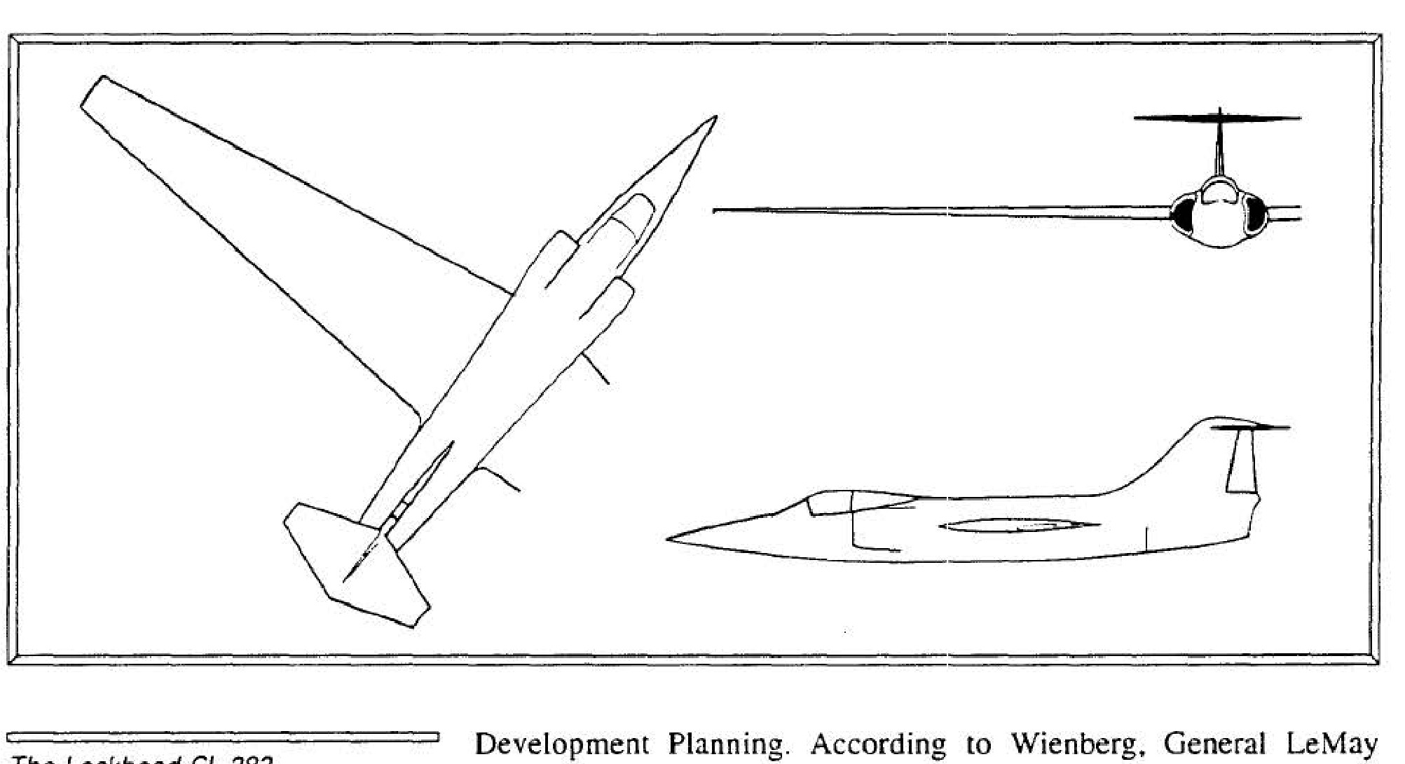
The Lockheed CL-282
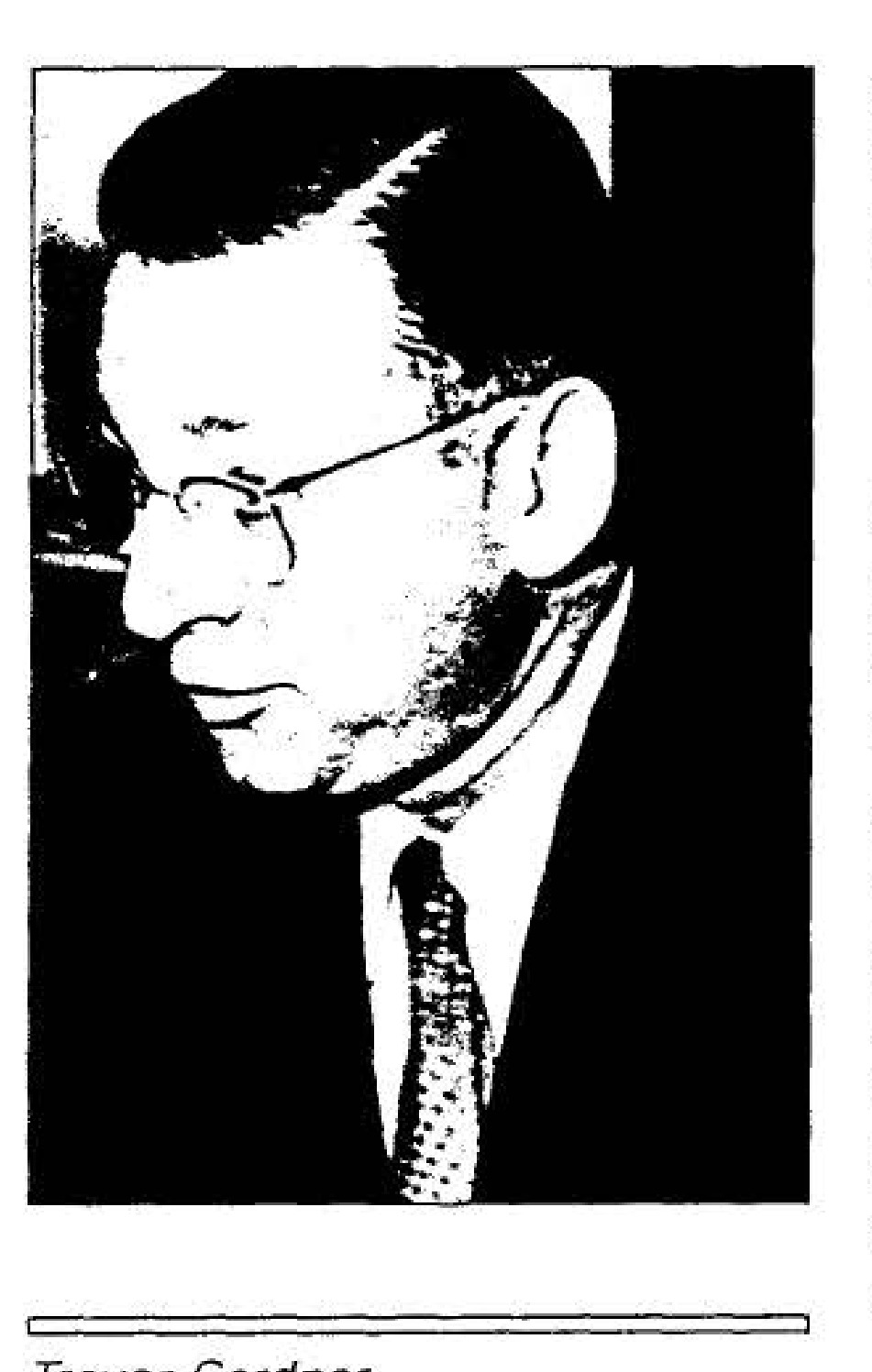
Trevor Gardner
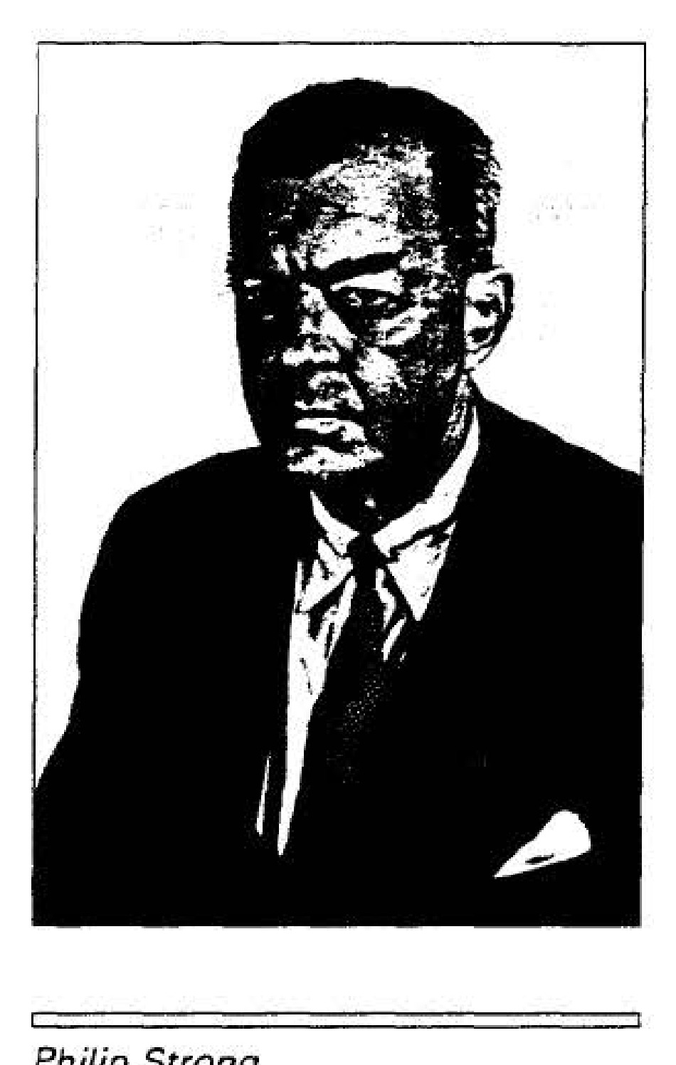
Philip Strong
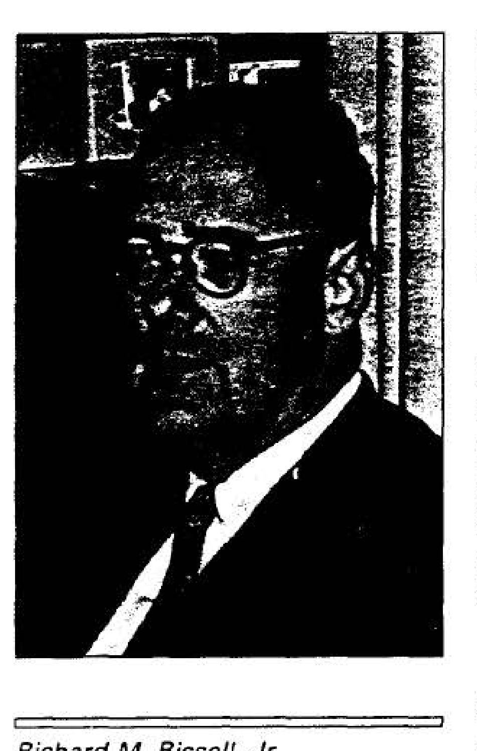
Richard M. Bissell, Jr.
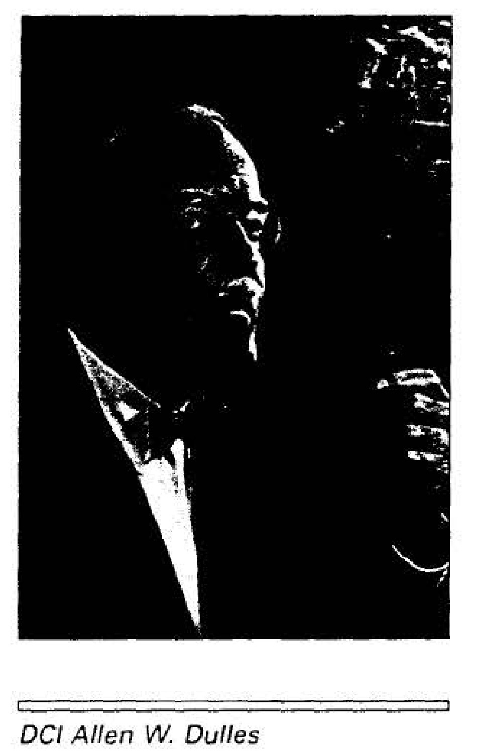
DCI Allen W. Dulles
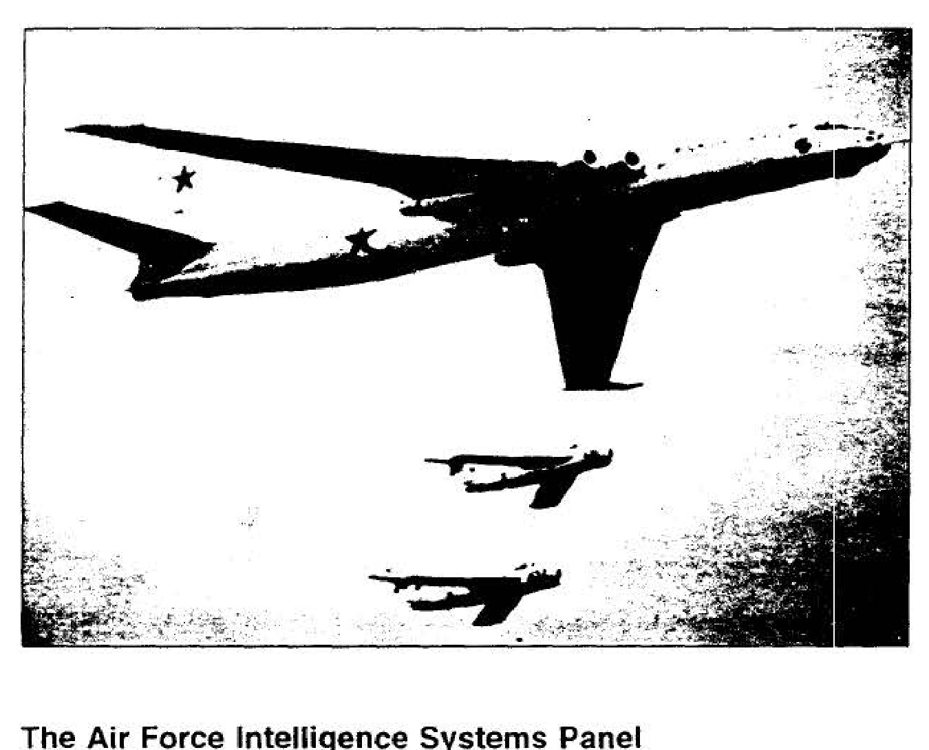
Soviet Myasishchev-4 bomber (the Bison)
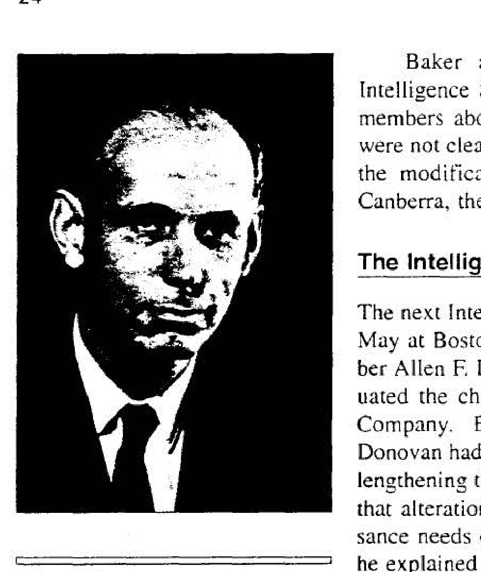
Allen F. Donovan
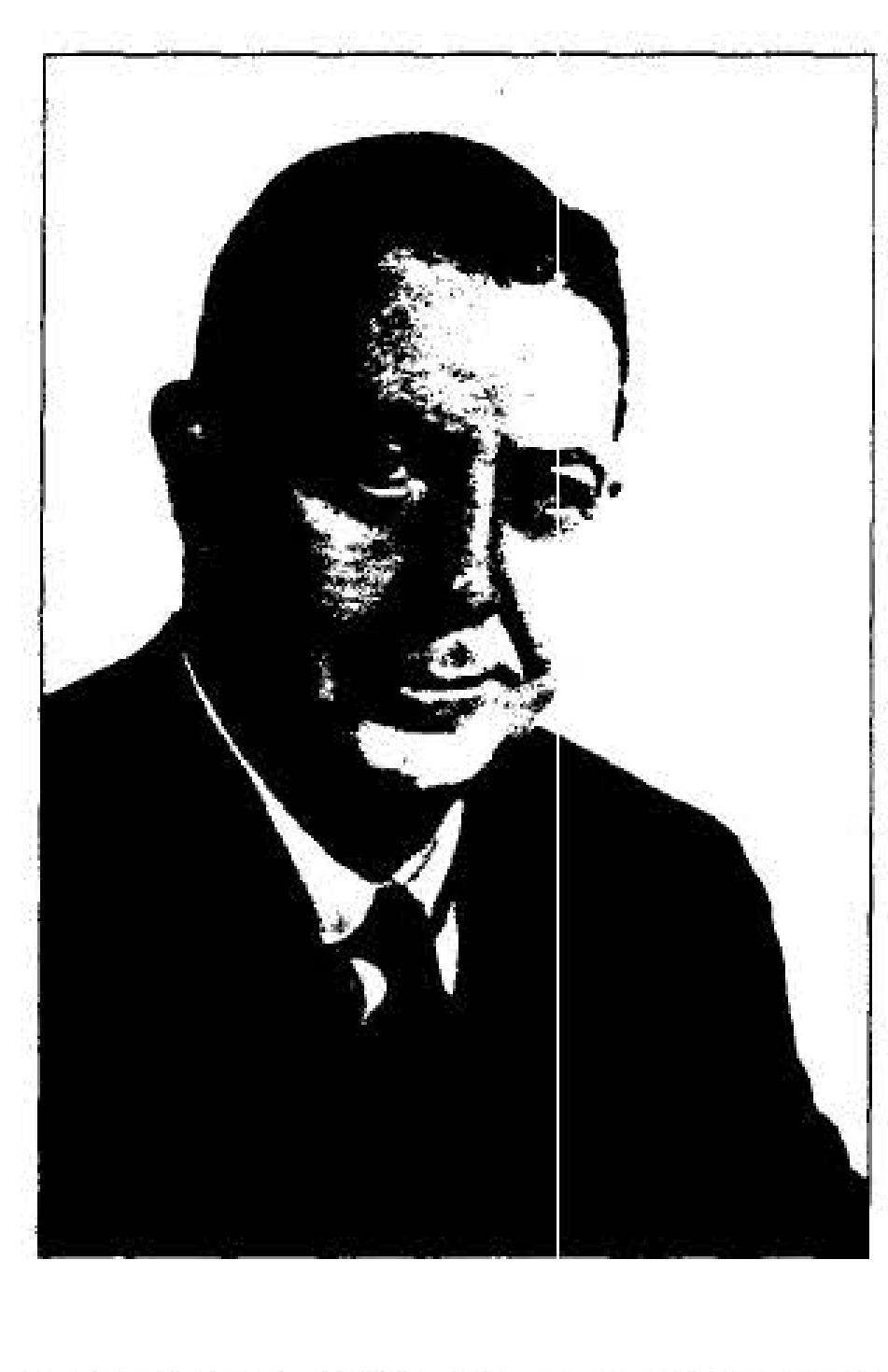
James R. Killian, Jr.
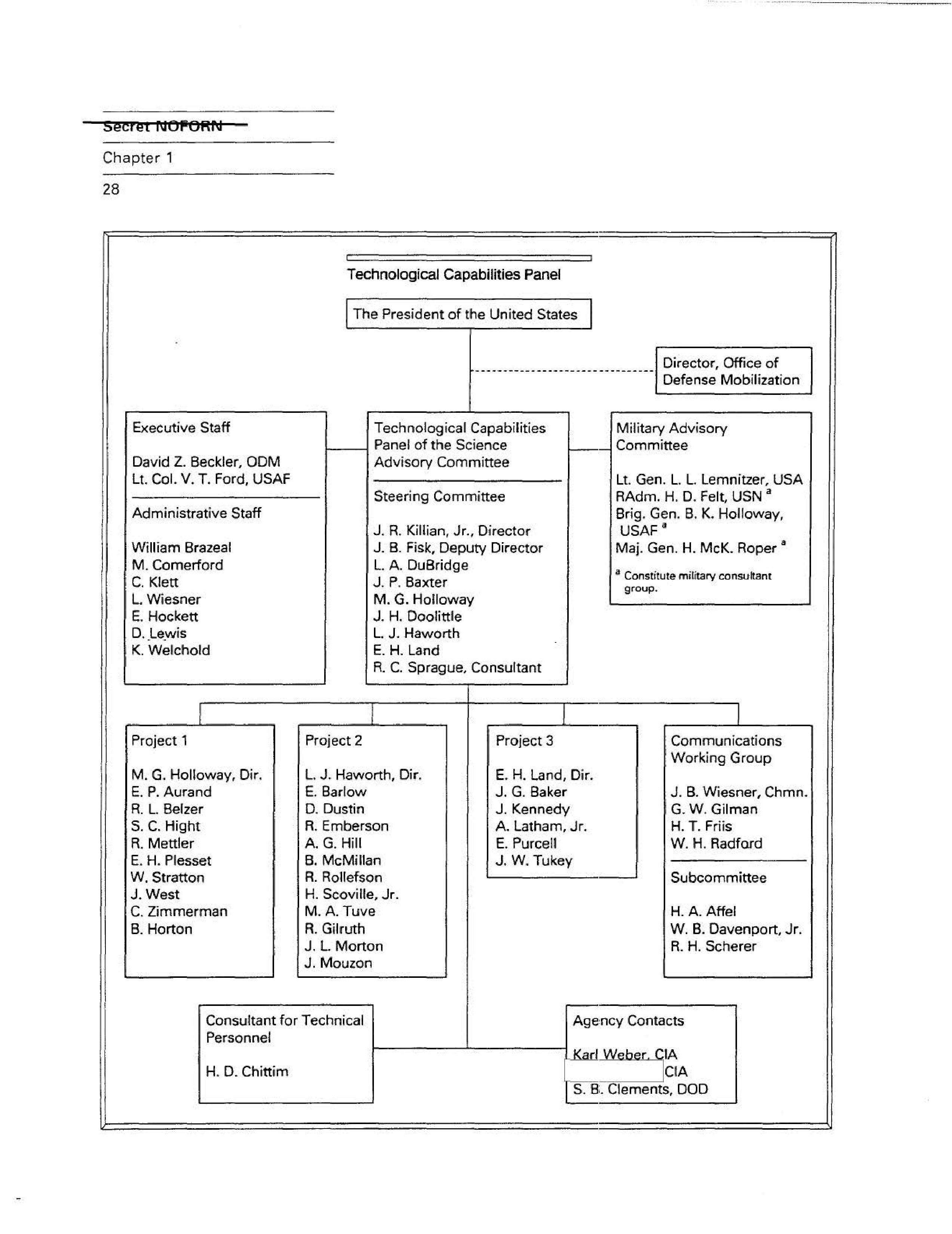
Technological Capabilities Panel
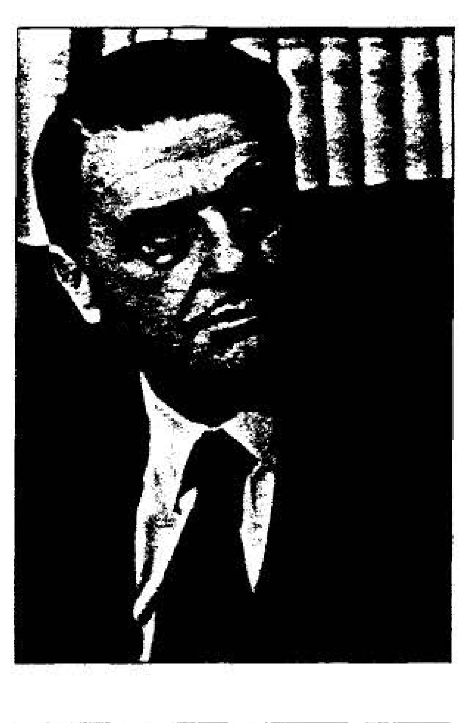
Edwin H. Land
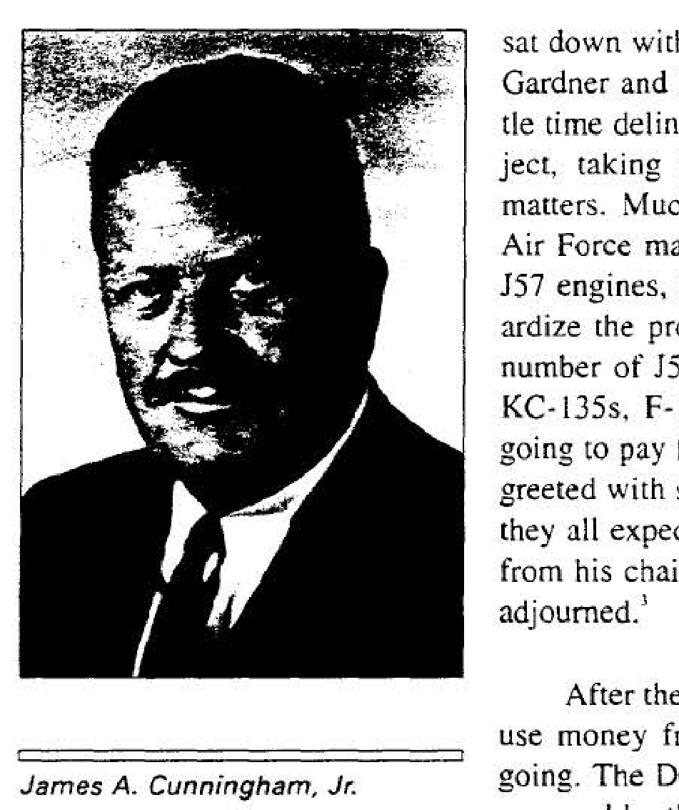
James A. Cunningham, Jr.
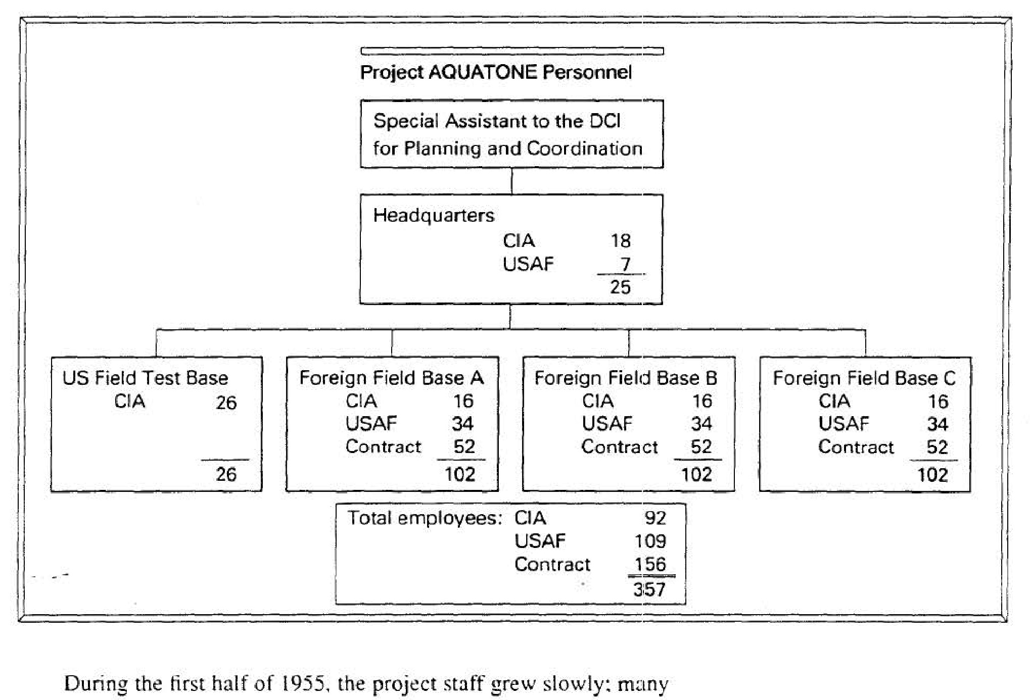
Project AQUATONE Personnel
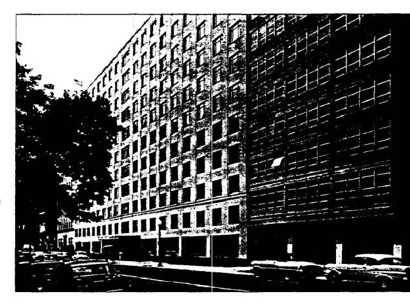
The Matomic Building
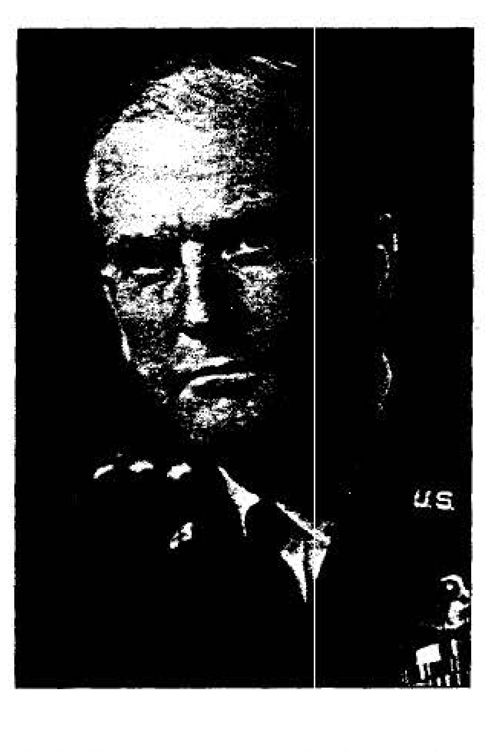
DDCI Charles Pearre Cabell
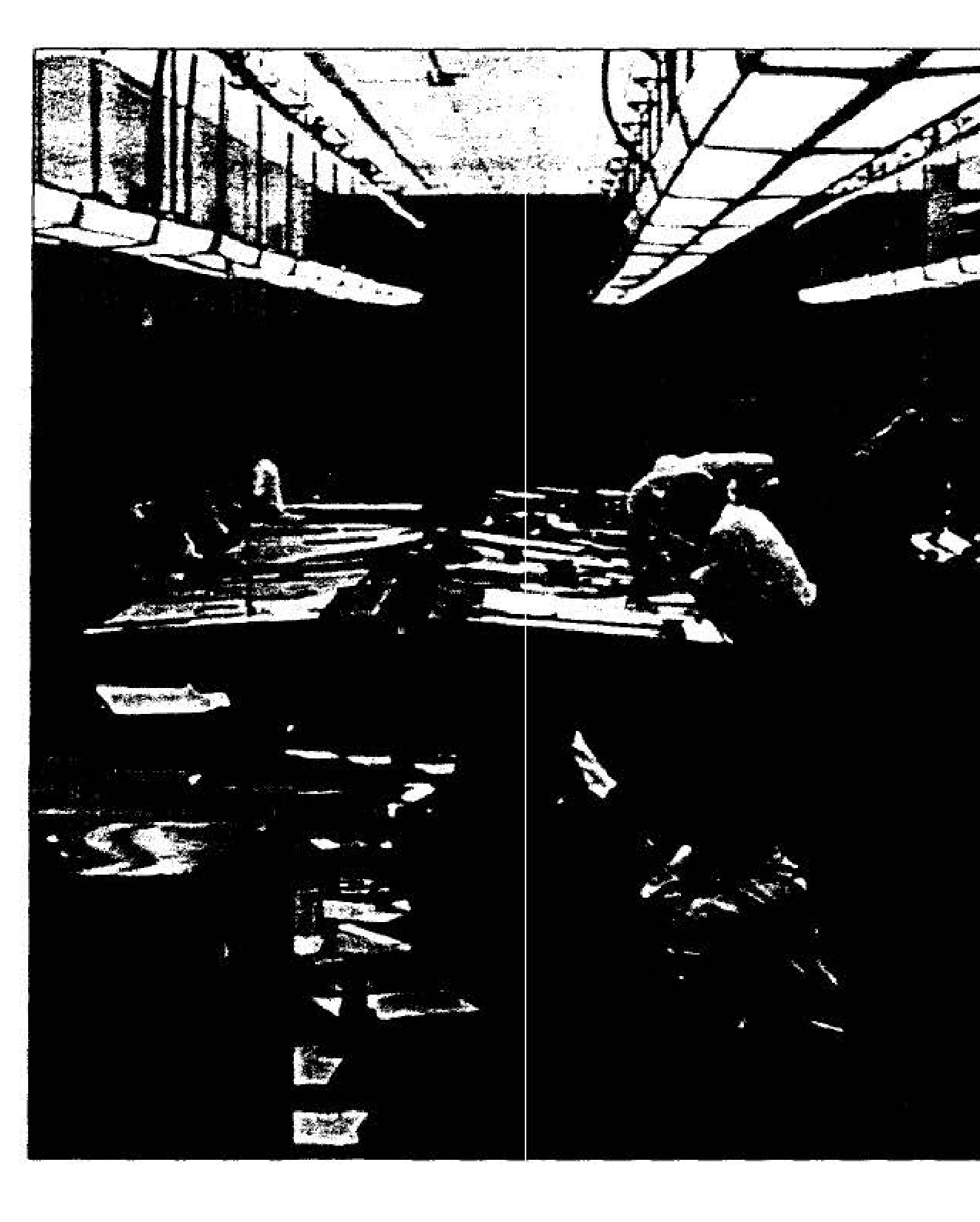
Skunk Works Design Staff
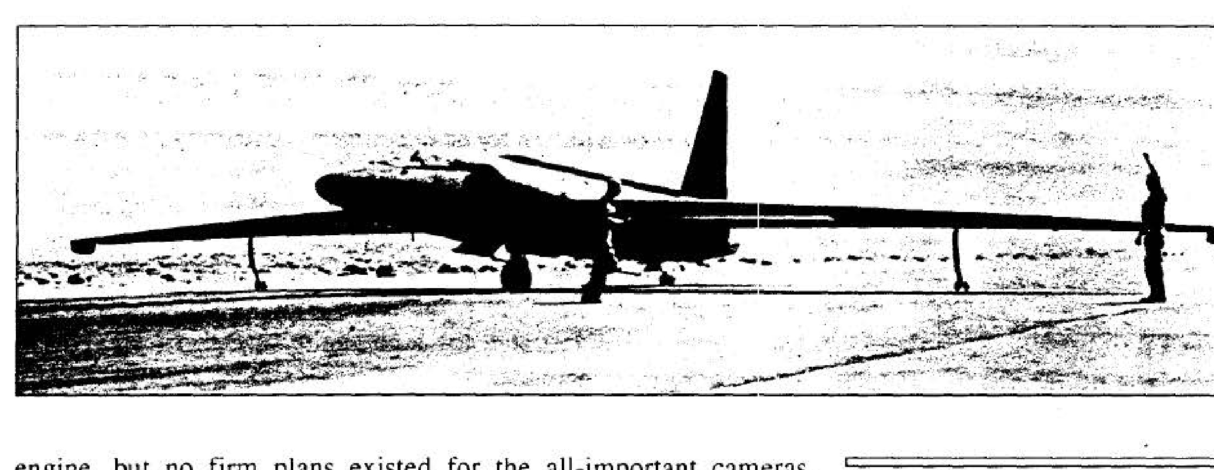
U-2 at testing site before attachment of wings and tail assembly
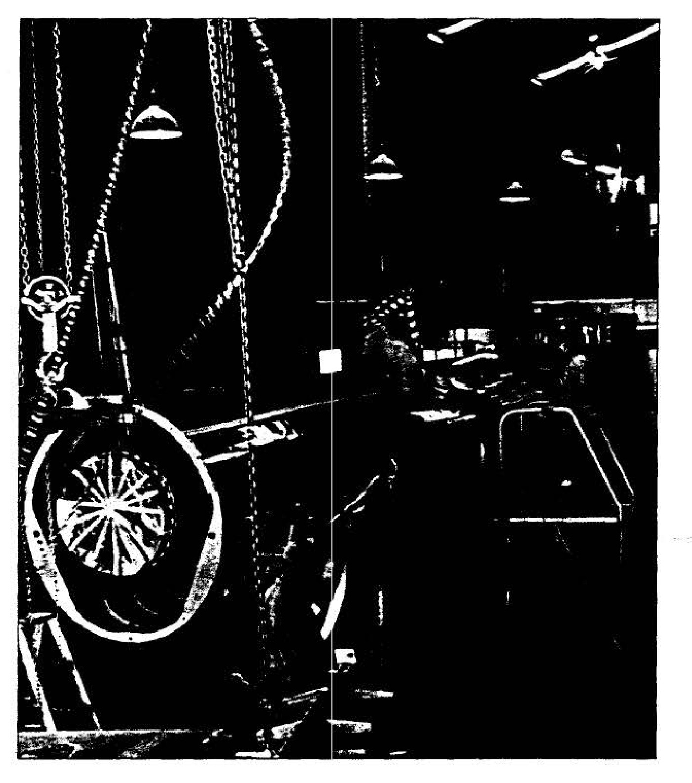
U-2 landing gear and pogos
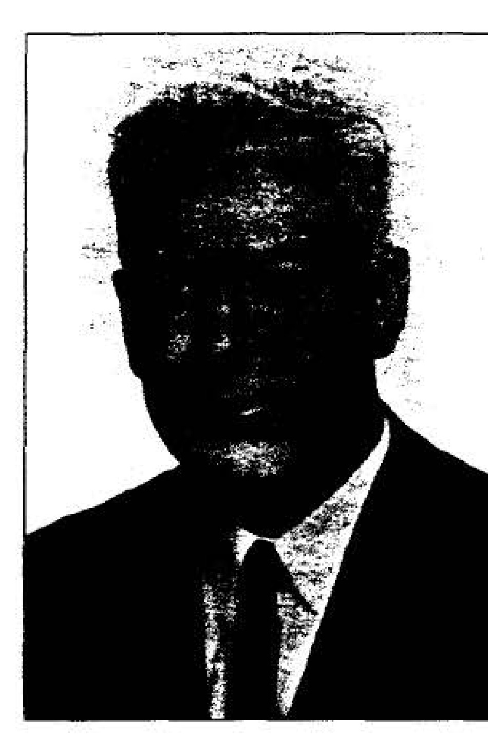
James G. Baker
A-1 camera
A-2 camera

B camera
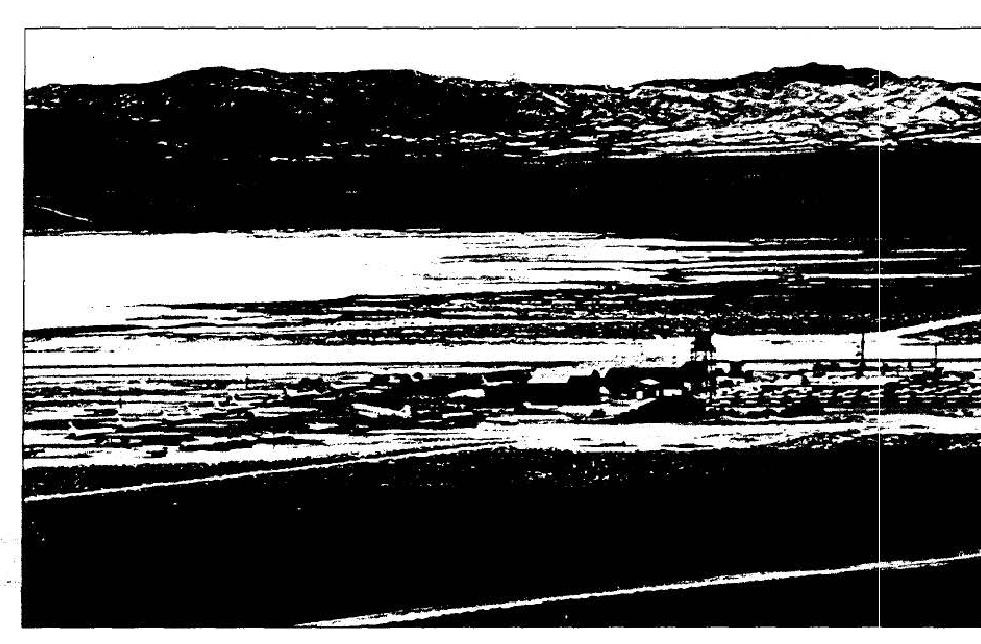
Area 51, the Ranch
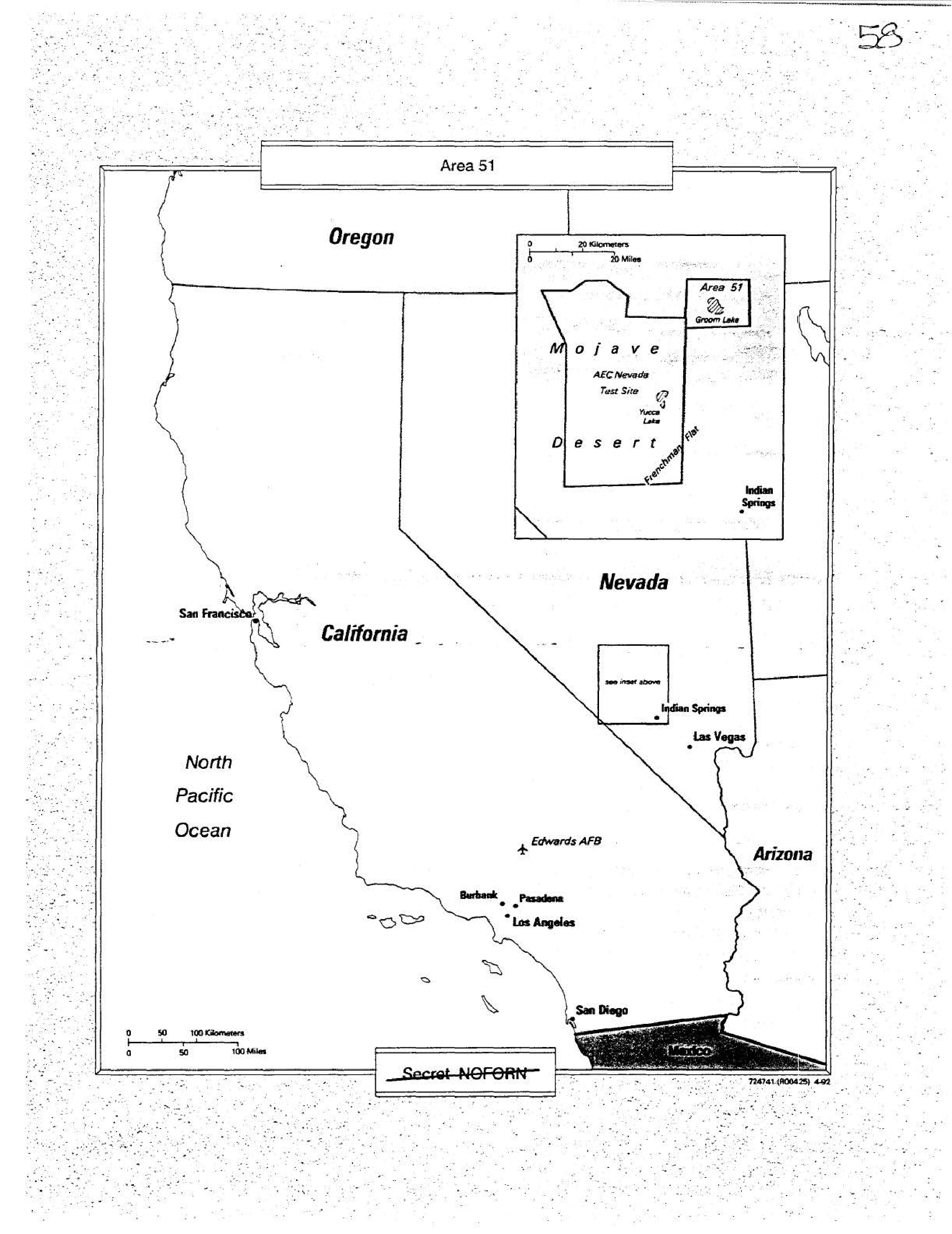
Area 51
Osmund J. Ritland
Leo P. Geary
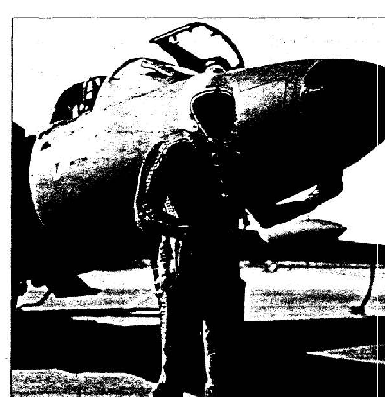
MC-2 partial-pressure suit (seen on pilot Francis Gary Powers)
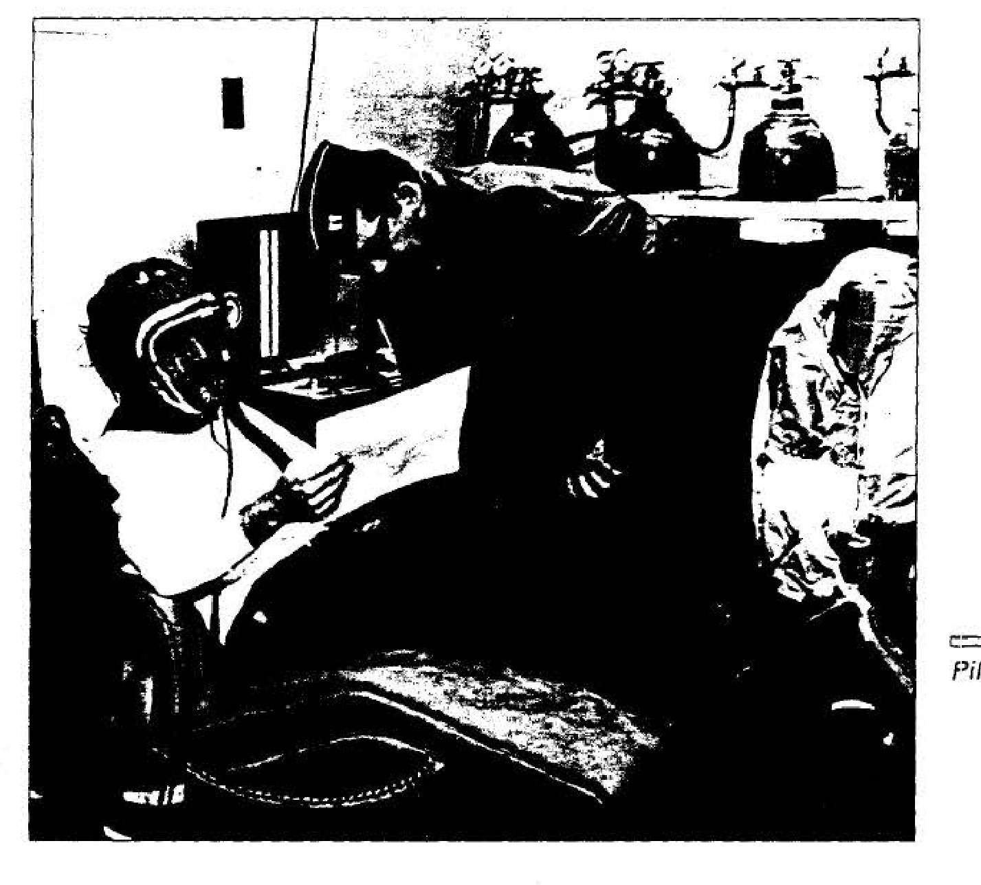
Pilot undergoing prebreathing
Arrival of U-2 prototype at Area 51 (left)
Article 341, the U-2 prototype (below)
First flight of the U-2, 4 August 1955
A-2 camera being installed in U-2
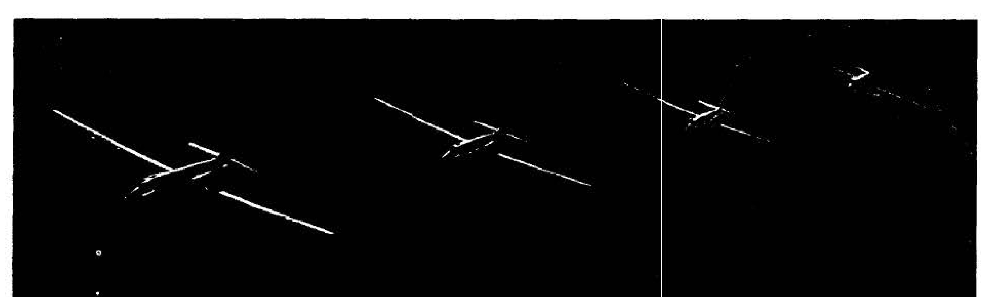
U-2 detachment in formation over Nevada
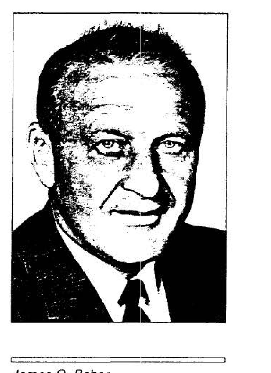
James Q. Reber
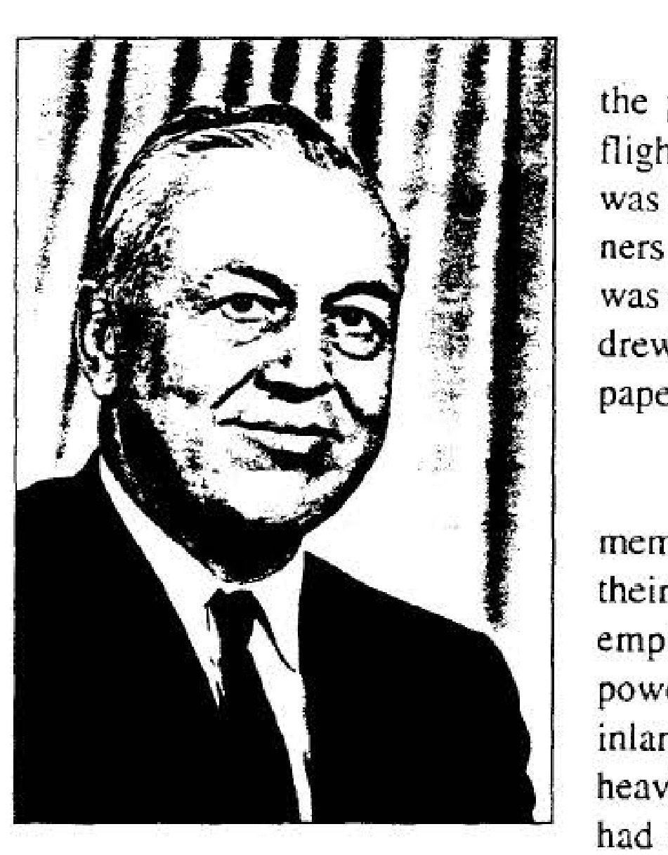
Arthur C. Lundahl
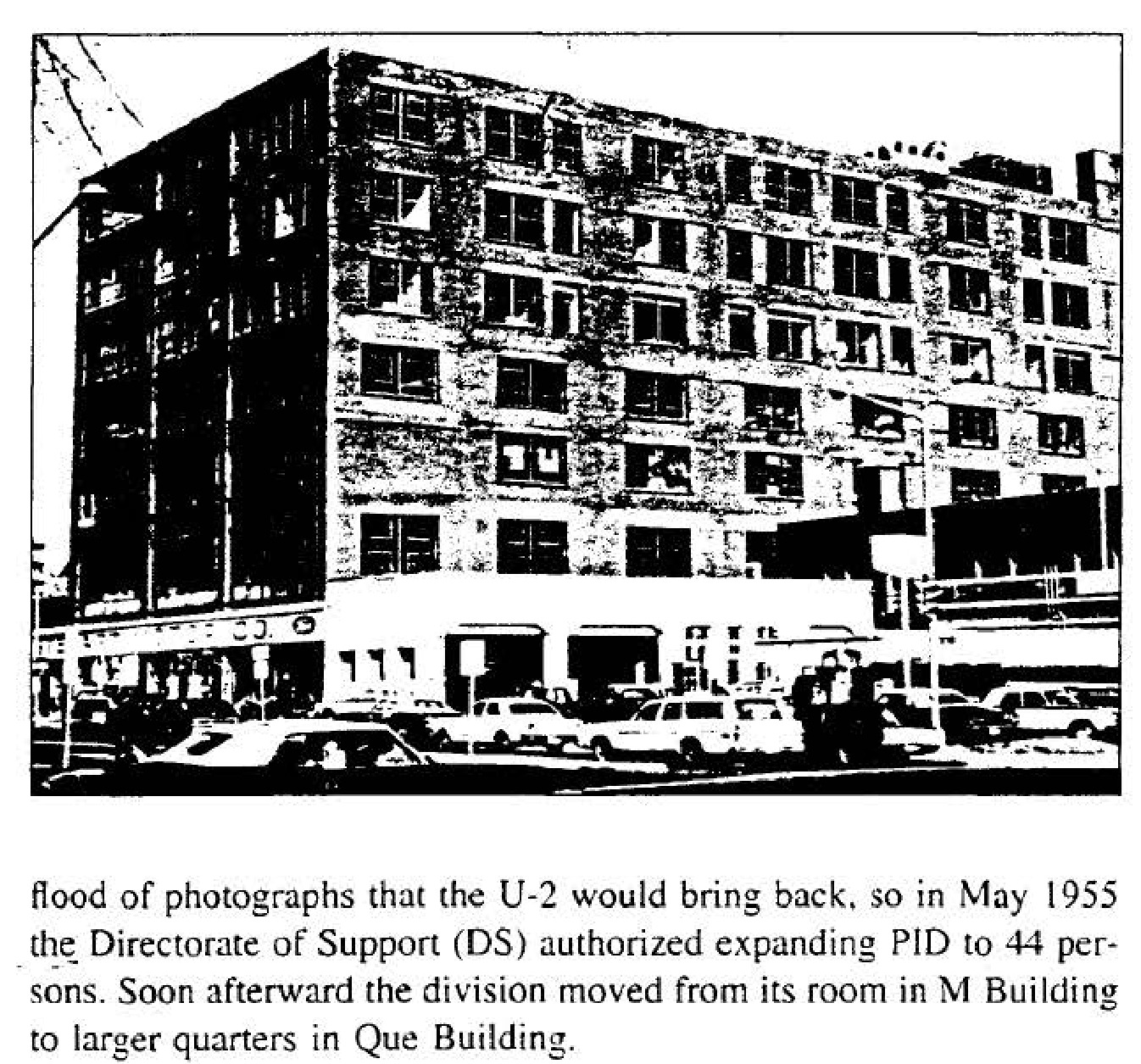
The Steuart Building, home of the Photo-Intelligence Division
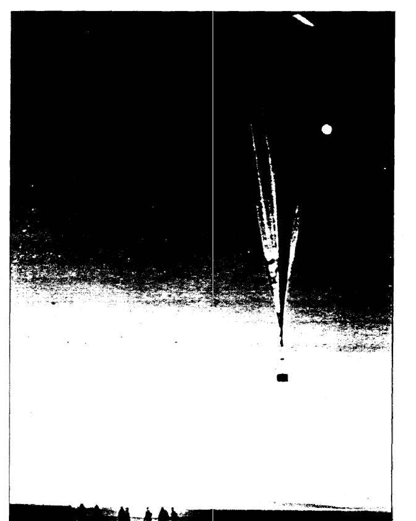
Project GENETRIX balloon launch
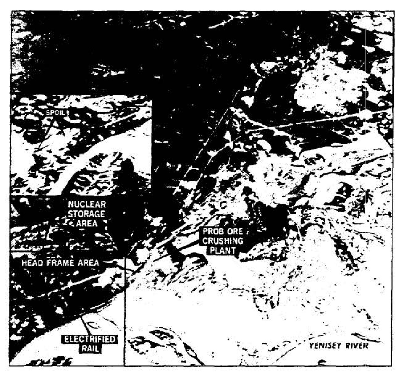
Photograph of Dodonovo Atomic Energy complex taken by a Project GENETRIX balloon
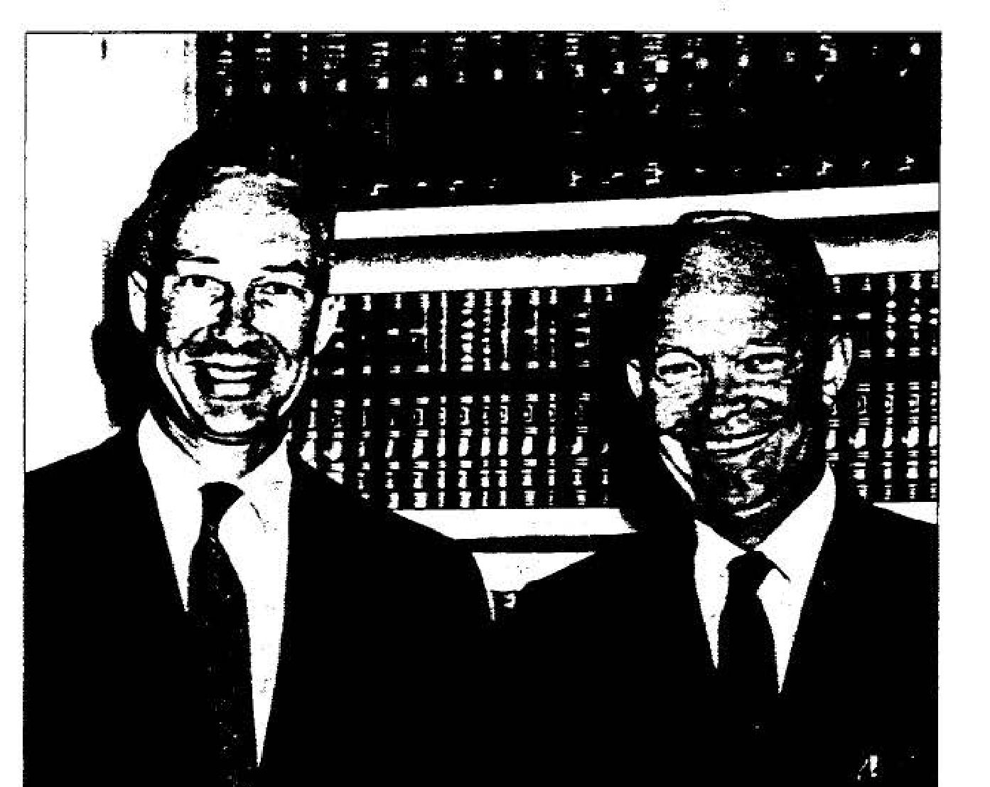
Colonel Goodpaster with President Eisenhower
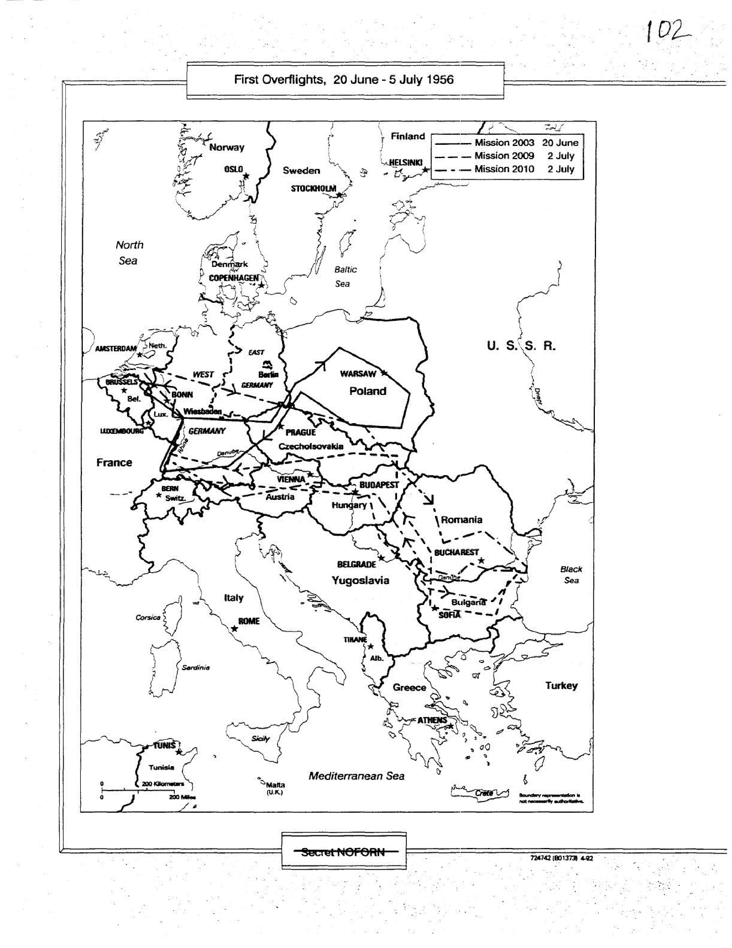
First Overflights, 20 June - 5 July 1956
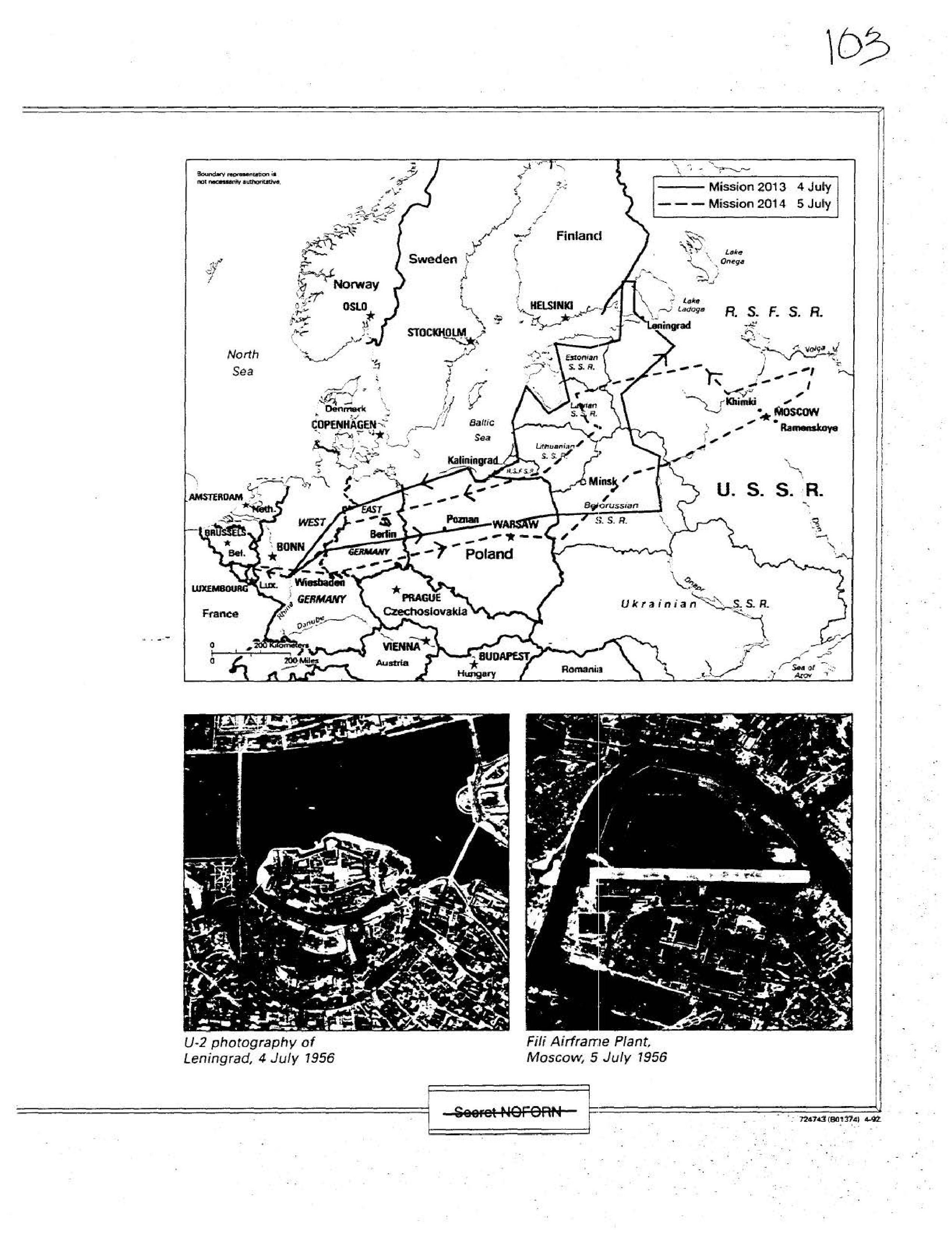
Map showing Mission 2013 (4 July) and Mission 2014 (5 July)
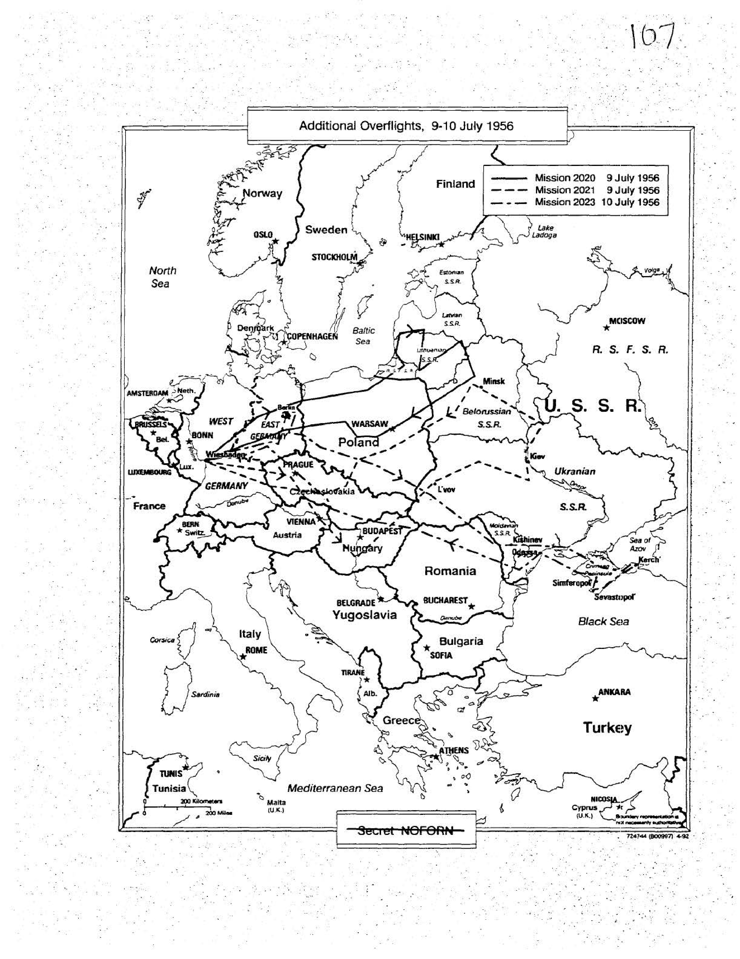
Additional Overflights, 9-10 July 1956
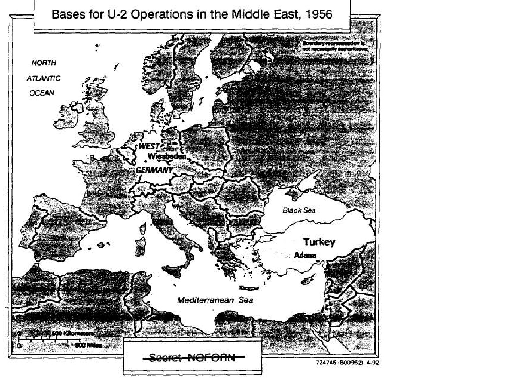
Bases for U-2 Operations in the Middle East, 1956
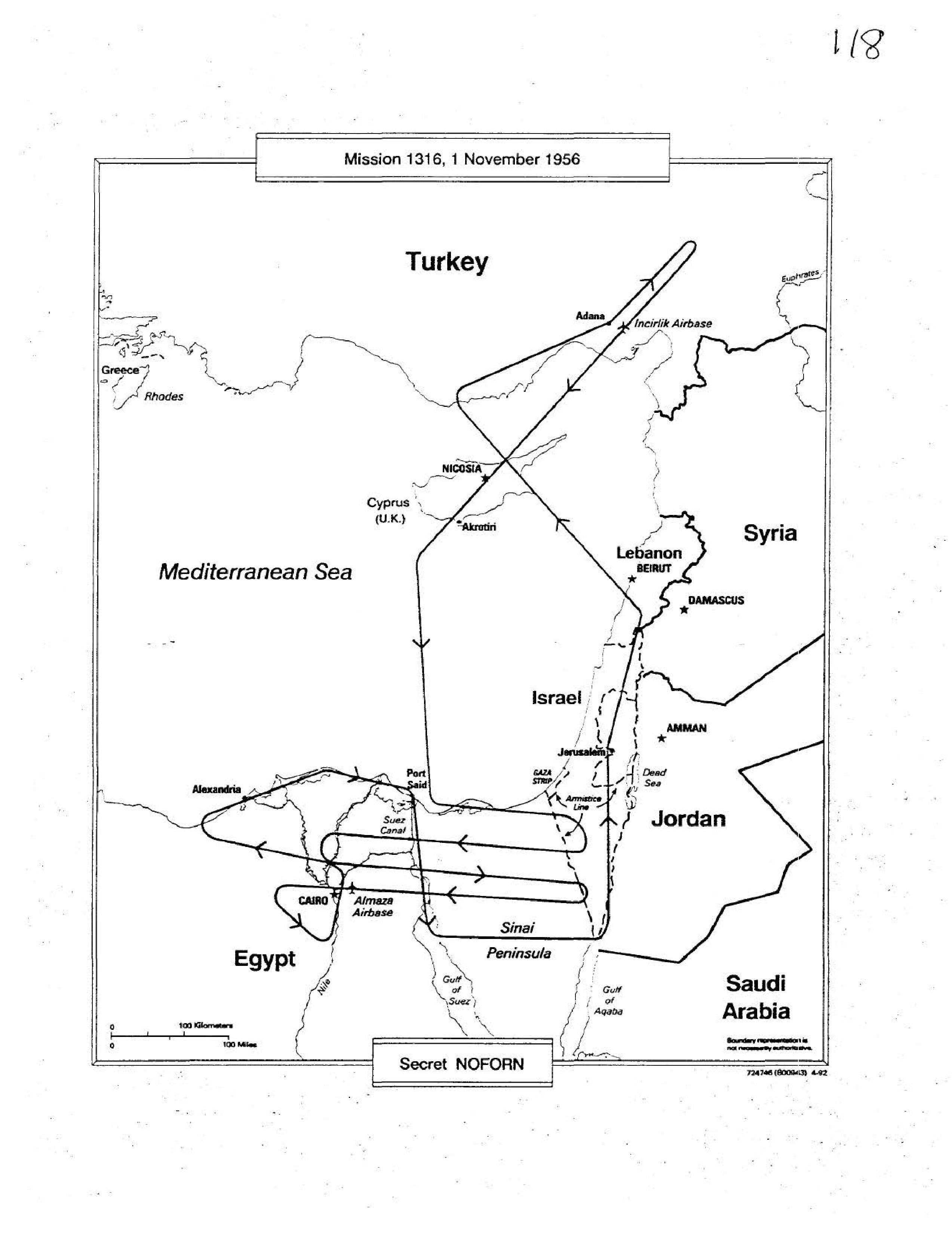
Mission 1316, 1 November 1956
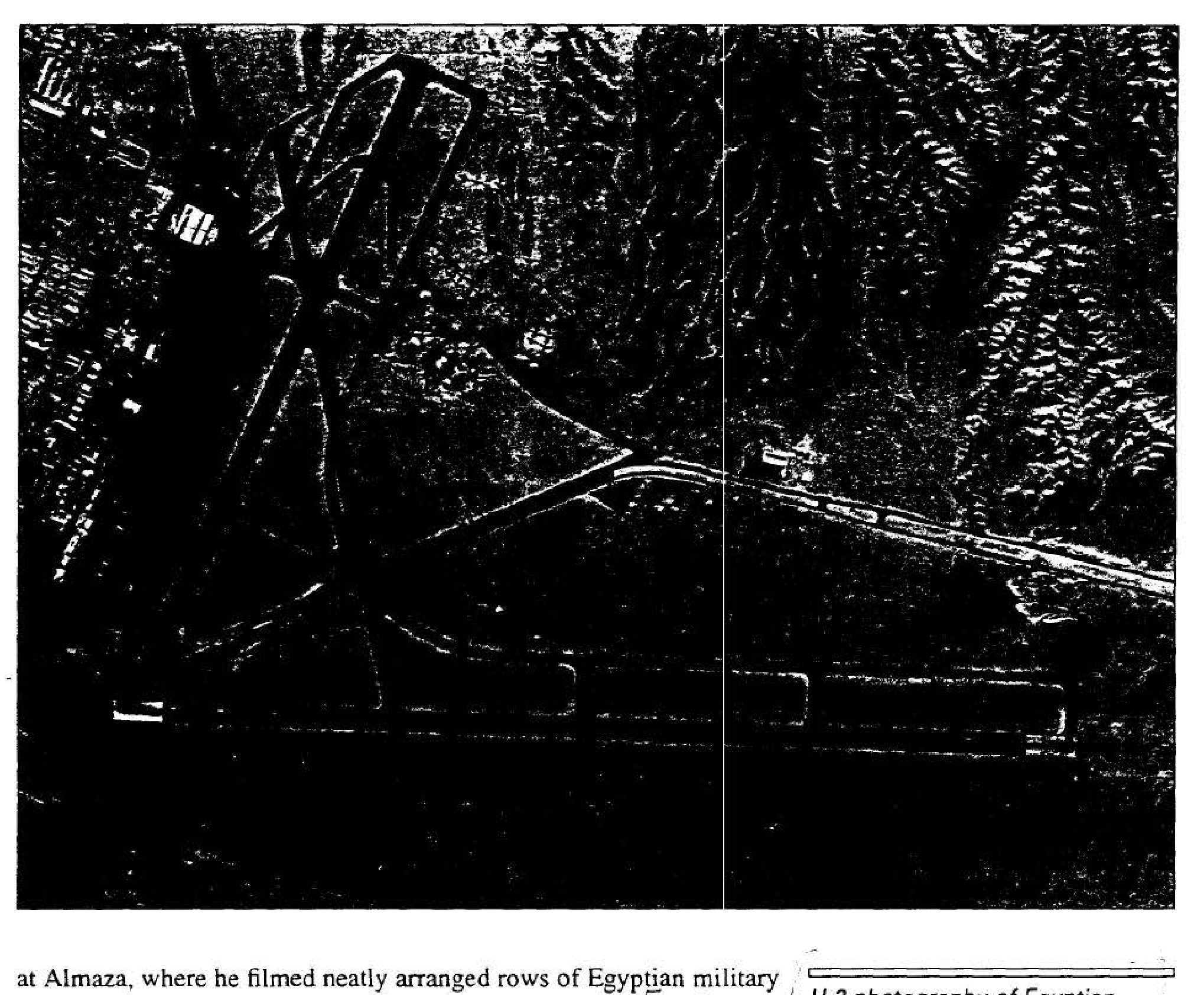
U-2 photography of Egyptian airbase at Almaza, 29 October 1956
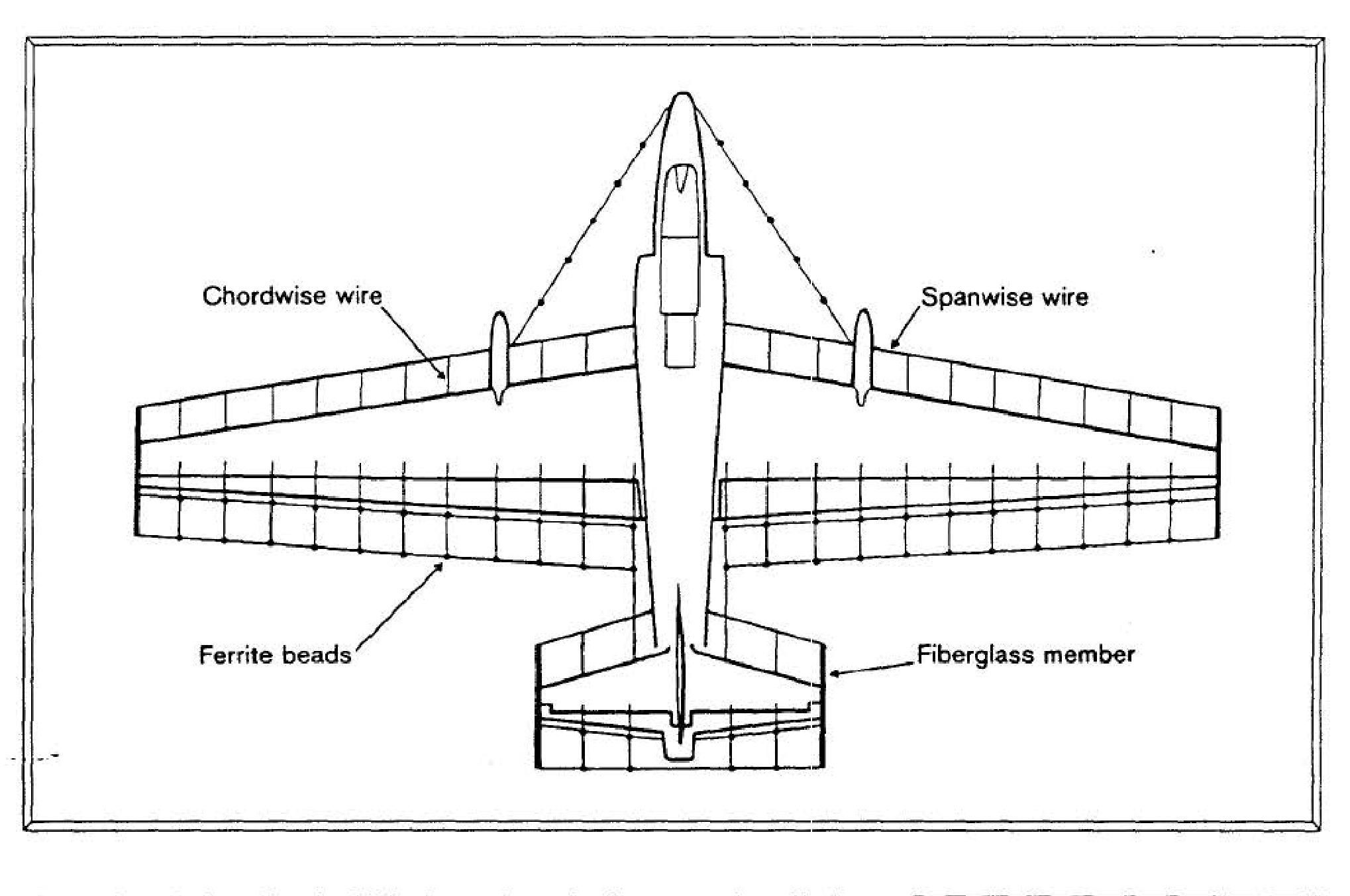
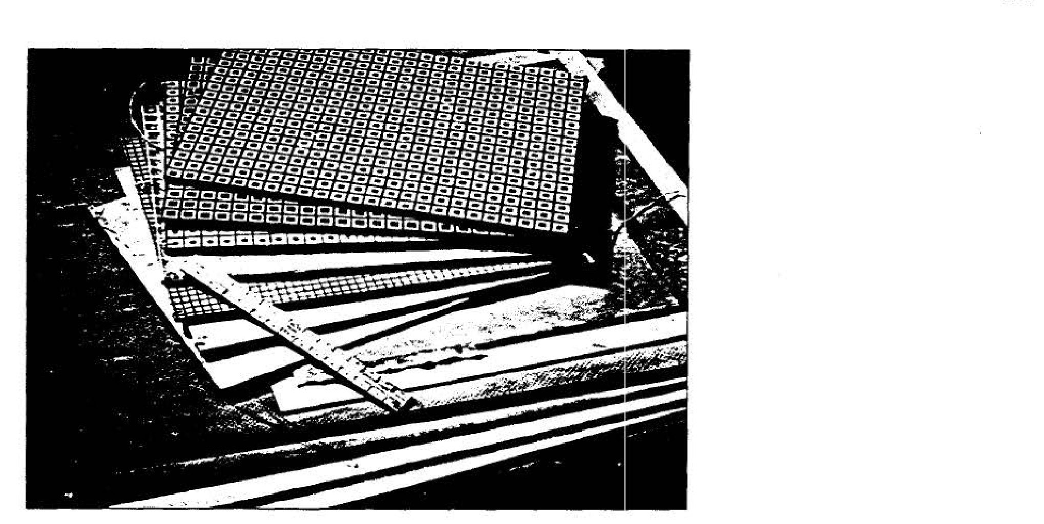
"Trapeze" antiradar attachments to the U-2
—
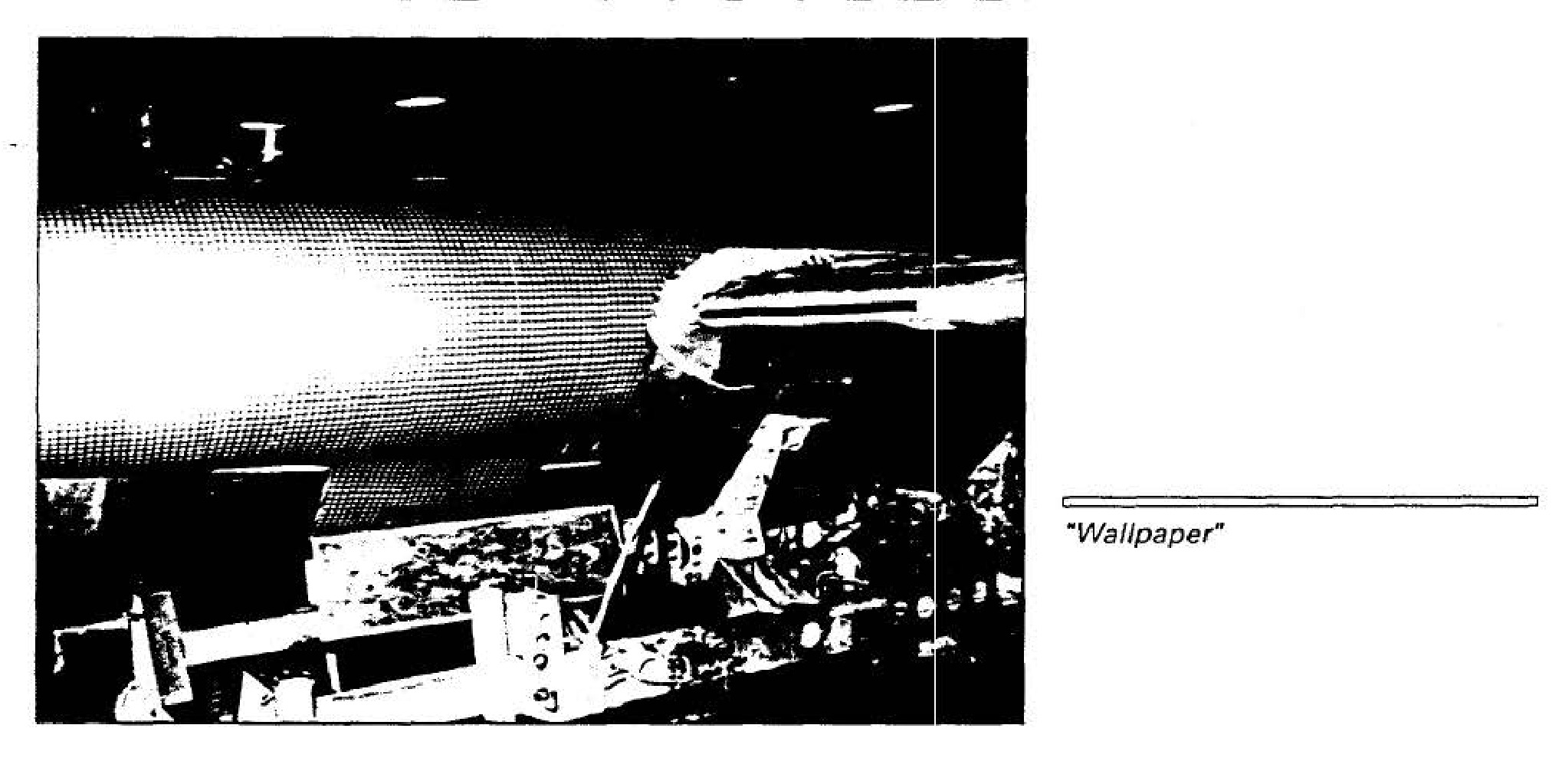
"Wallpaper"
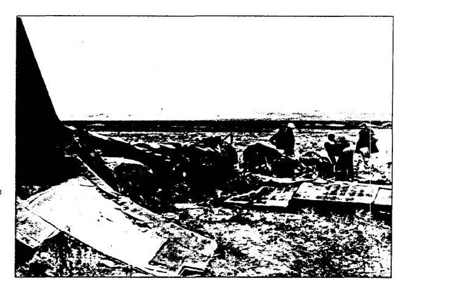
Wreckage of Article 341, 2 April 1957

Operation SOFT TOUCH Overflights, August 1957
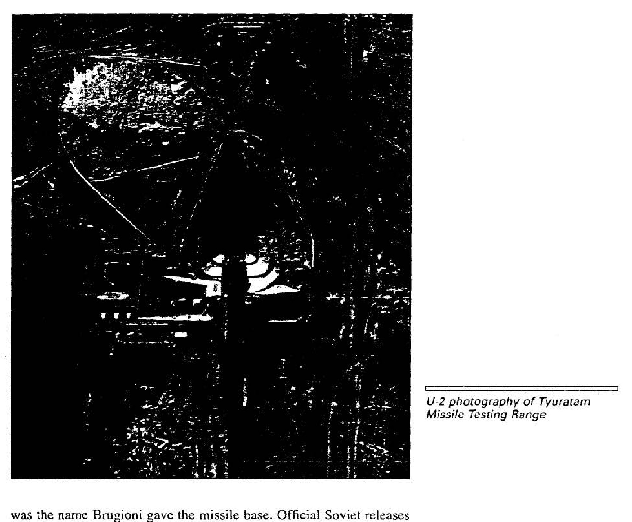
U-2 photography of Tyuratam Missile Testing Range
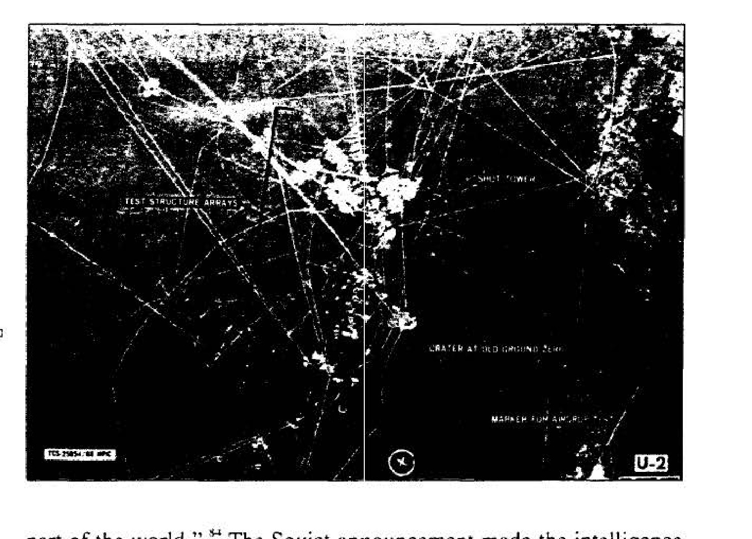
Semipalatinsk Nuclear Weapons Proving Ground, 22 August 1957
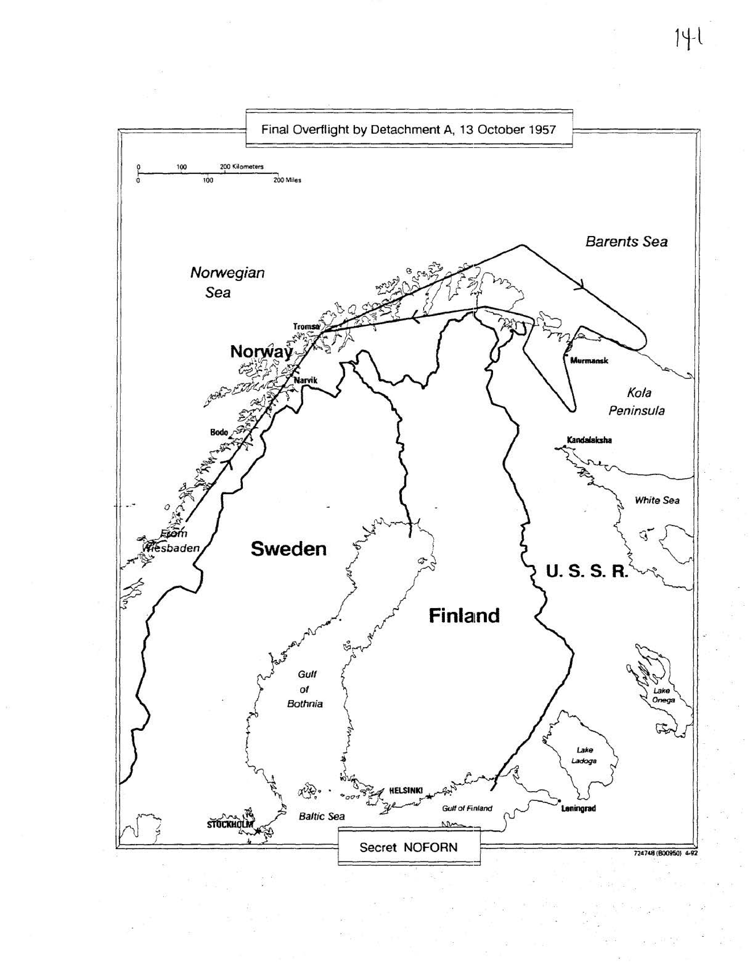
Final Overflight by Detachment A, 13 October 1957
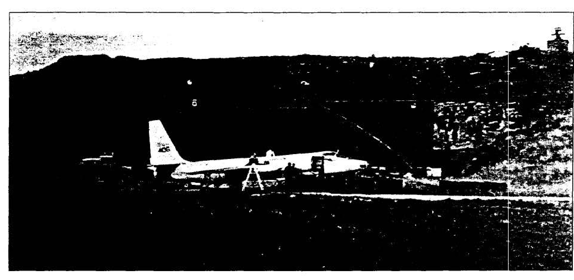
U-2 at Bodo, Norway
Equipment from a WS-461L balloon on display in Moscow, 11 October 1958
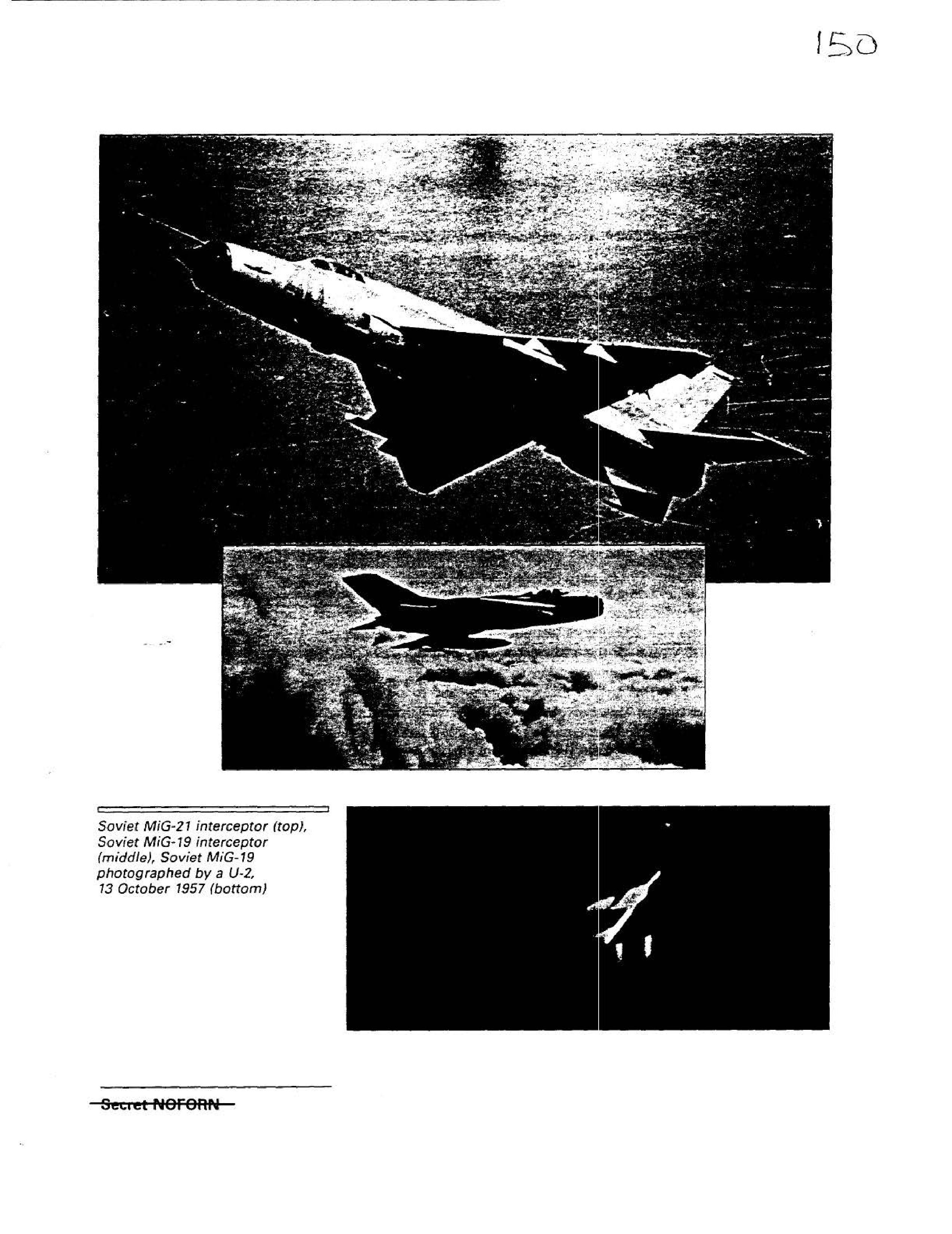
Soviet MiG-21 interceptor (top)
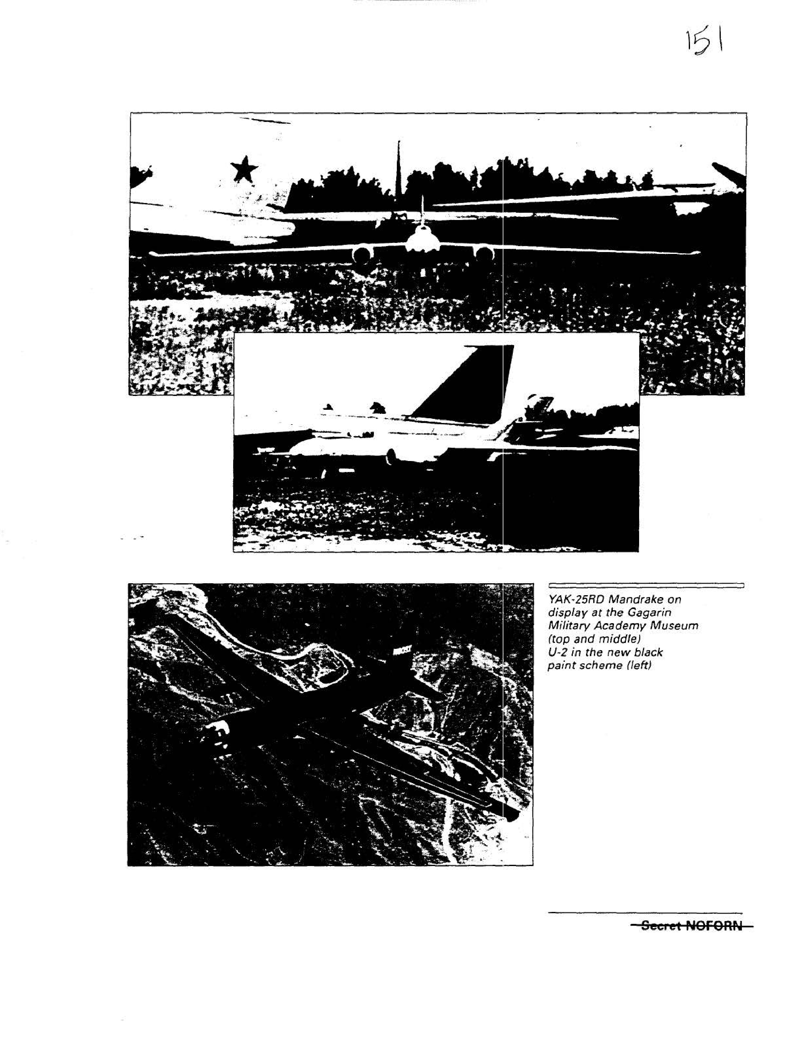
YAK-25RD Mandrake on display at the Gagarin Military Academy Museum (top)
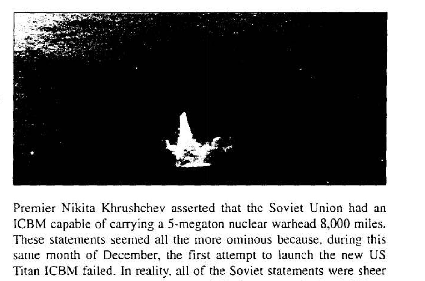
Launch of Sputnik, 4 October 1957
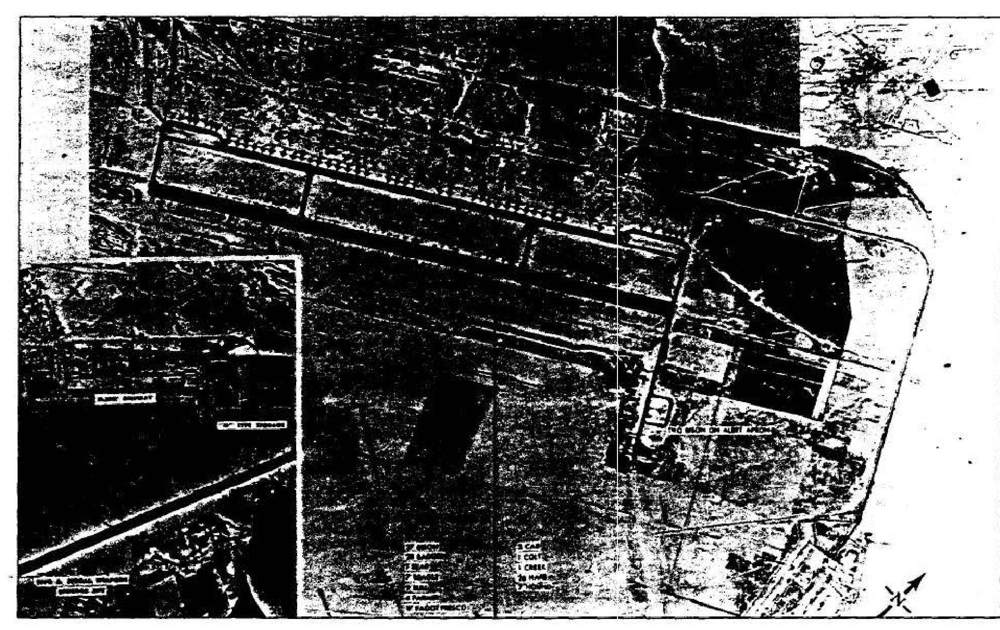
Saratov Engels Airfield, 6 December 1959
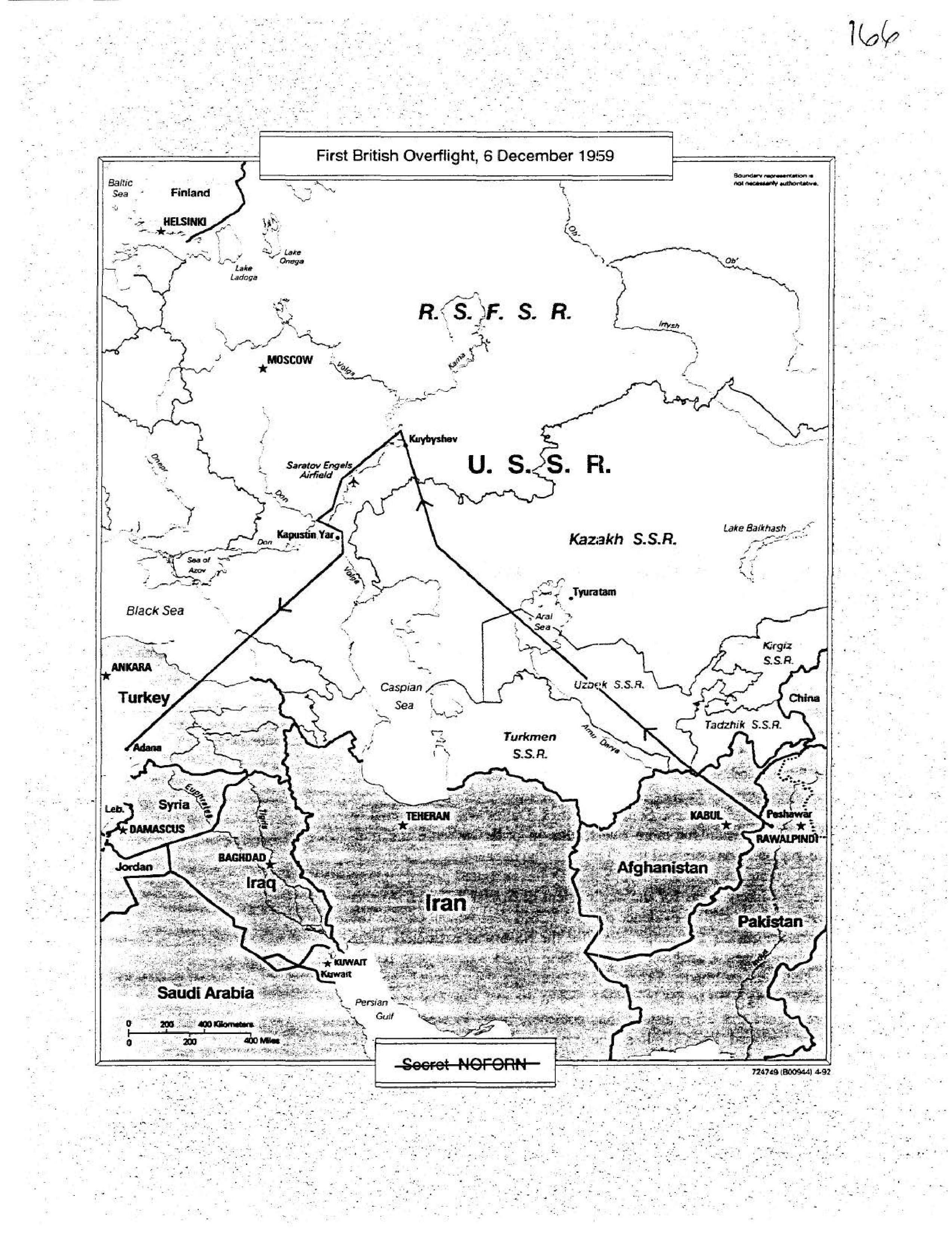
First British Overflight, 6 December 1959
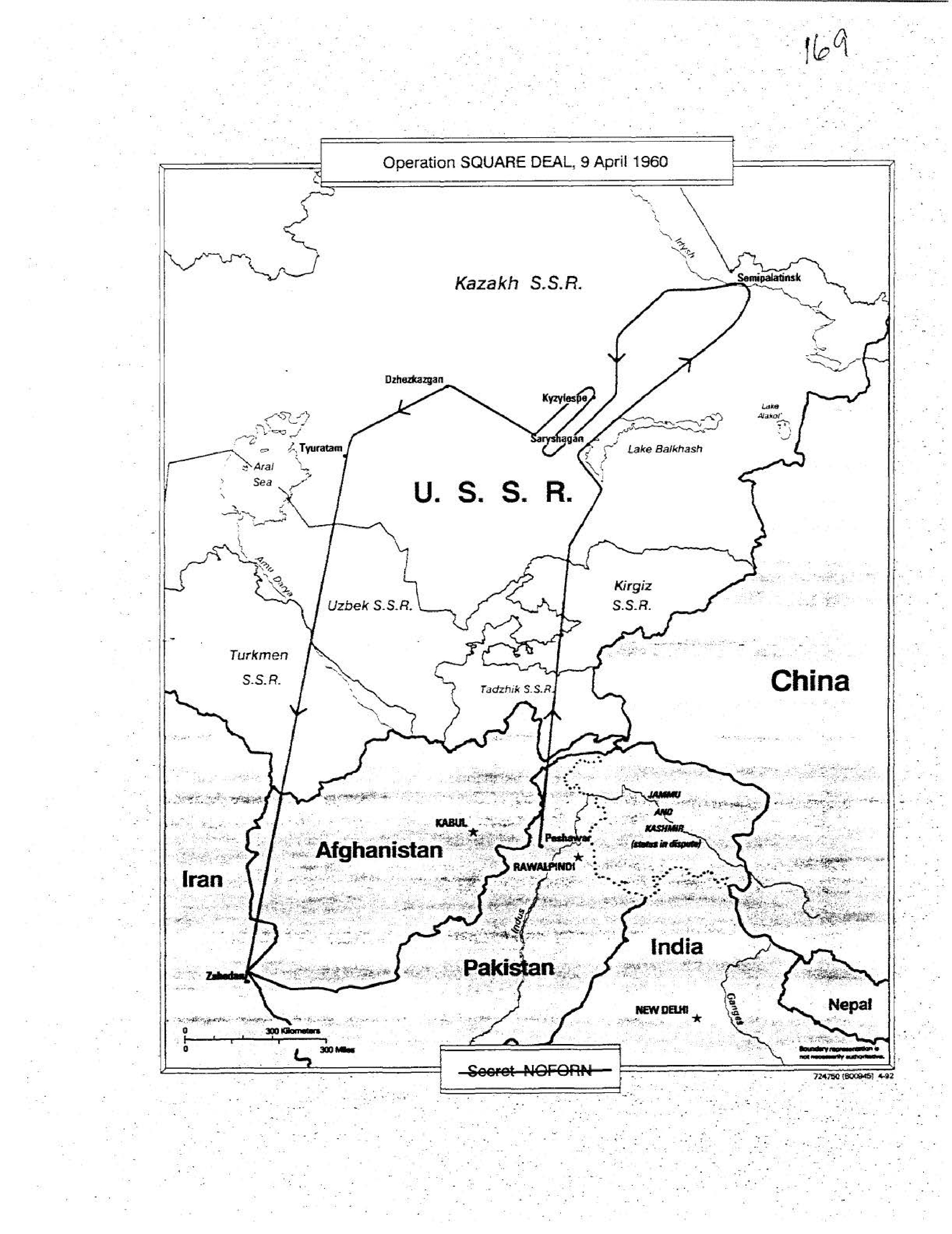
Map depicting the flight path of Operation SQUARE DEAL on 9 April 1960 over the USSR, originating from Peshawar, Pakistan.
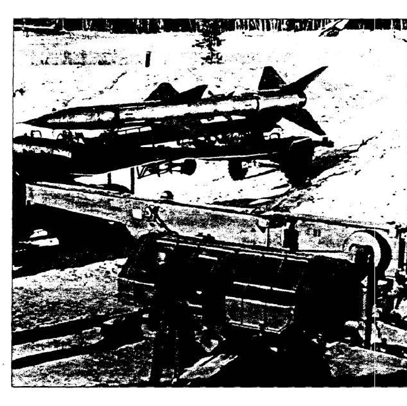
SA-2 surface-to-air missile
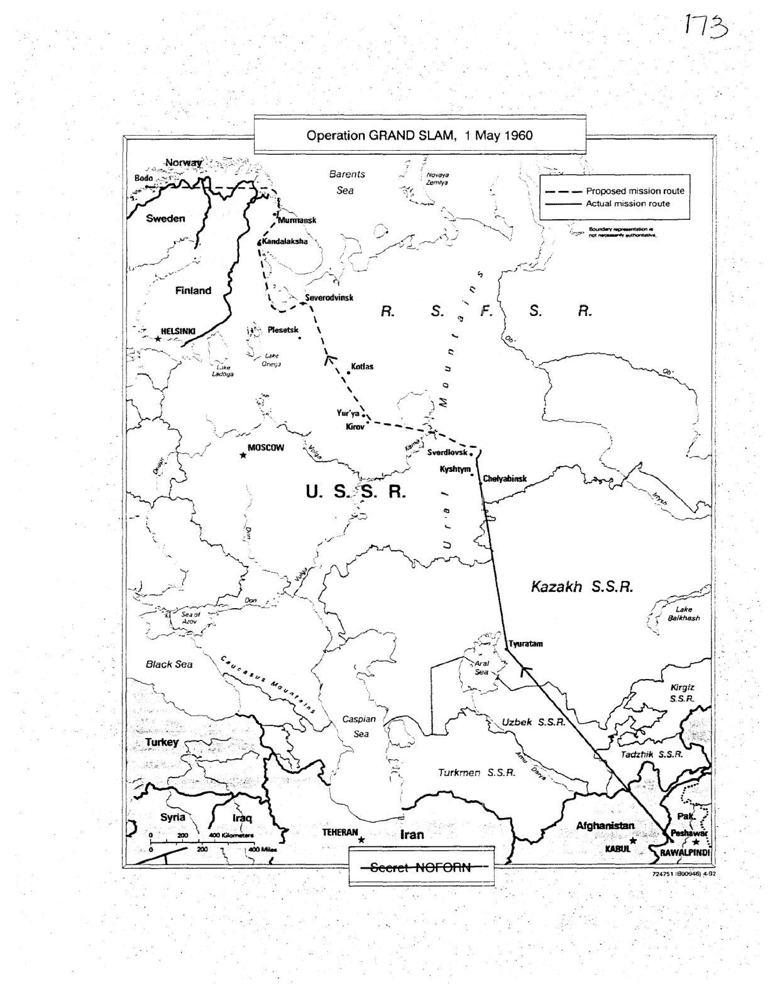
Map depicting the proposed and actual mission routes for Operation GRAND SLAM on 1 May 1960.
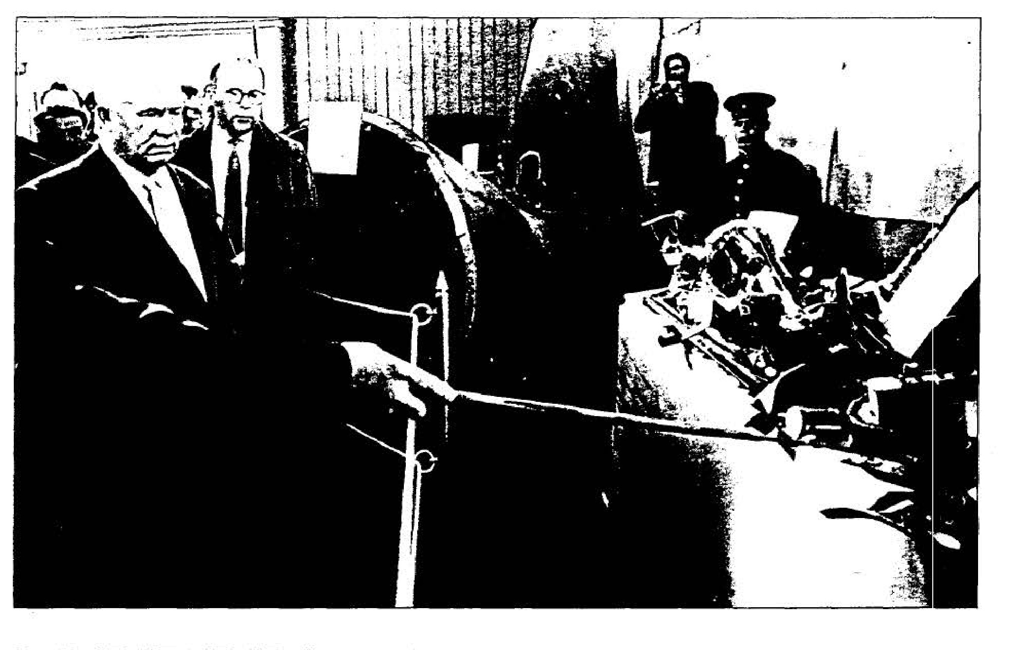
Khrushchev and the U-2 wreckage
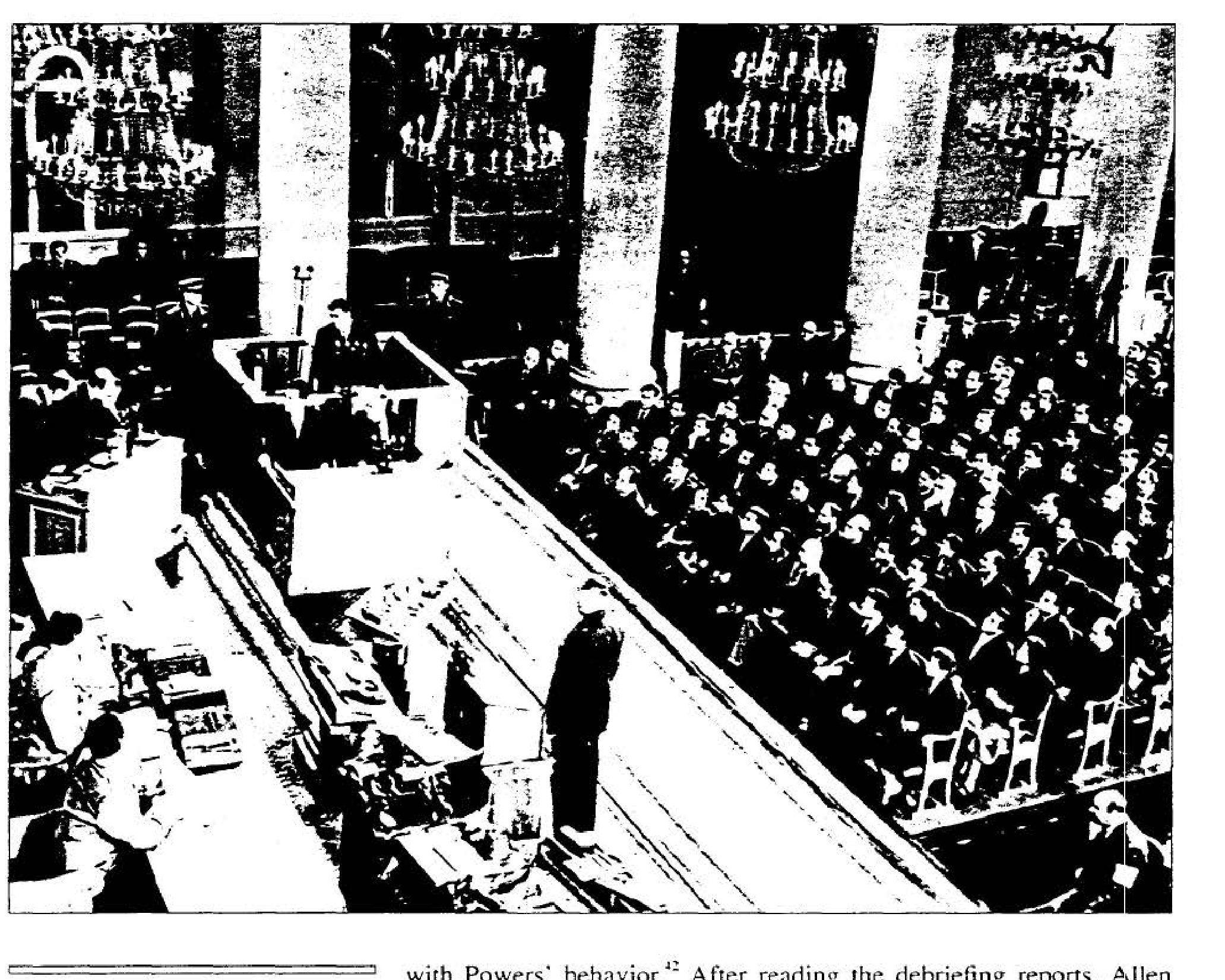
Trial of Francis Gary Powers
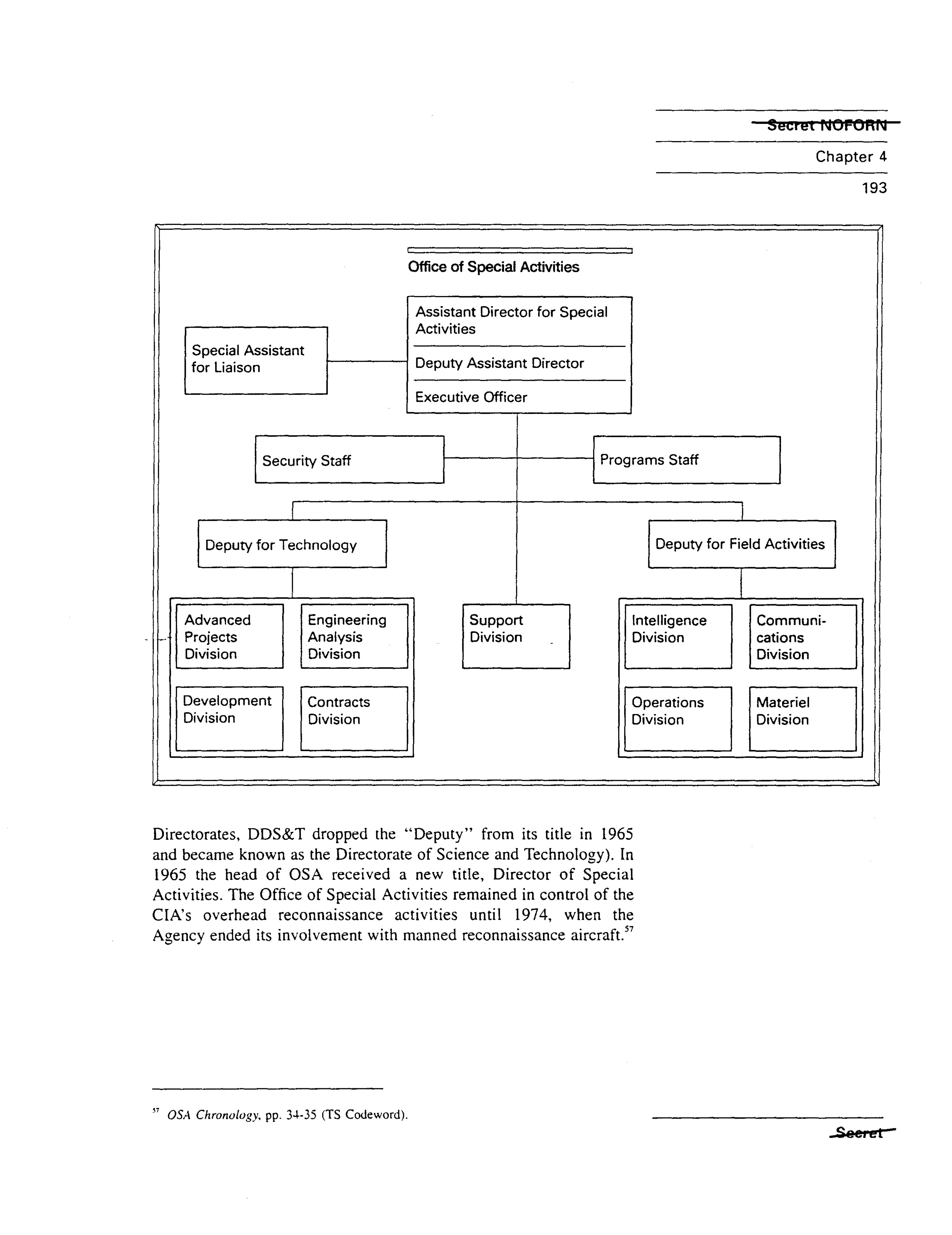
Office of Special Activities organizational chart.
Decorative number 5 in a diamond shape, marking the start of Chapter 5.
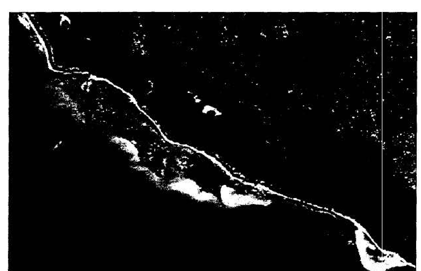
Aftermath of the Bay of Pigs invasion, 20 April 1961
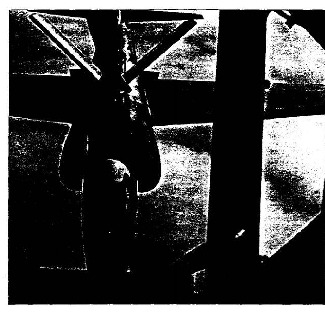
In-flight refueling of a U-2
DCI John A. McCone
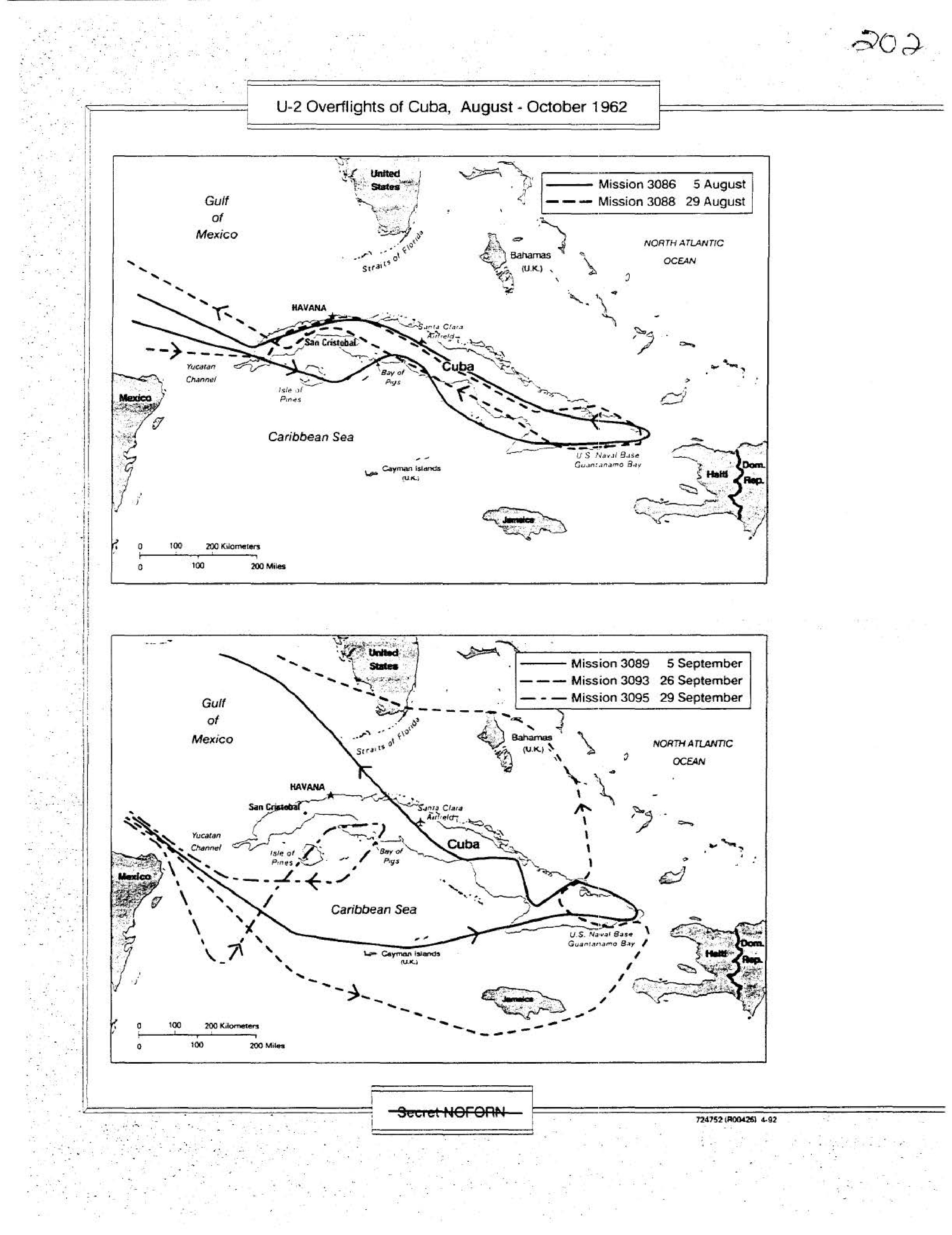
U-2 Overflights of Cuba, August - October 1962
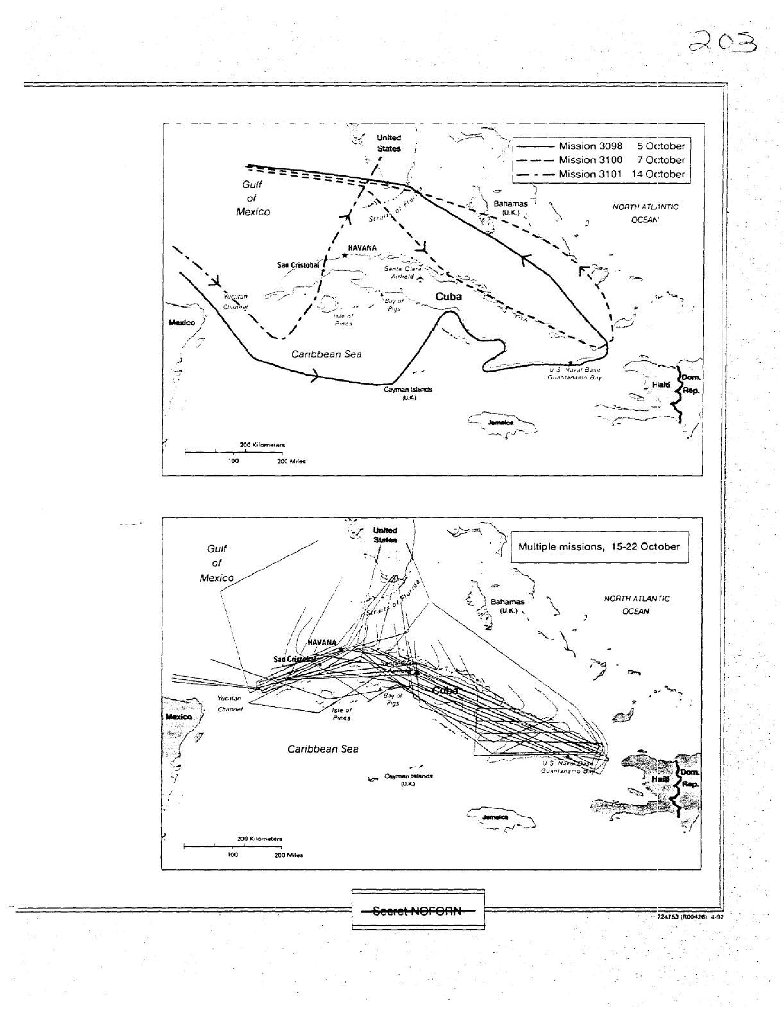
U-2 Overflights of Cuba, October 1962
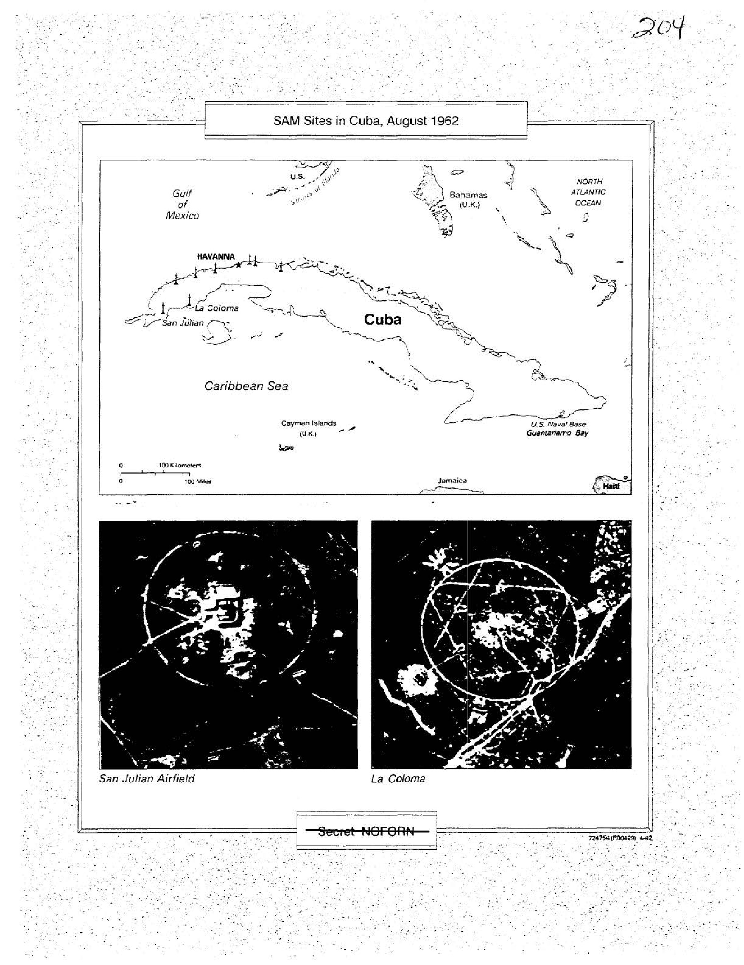
SAM Sites in Cuba, August 1962
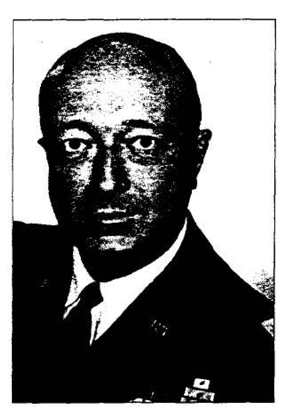
DDCI Marshall S. Carter
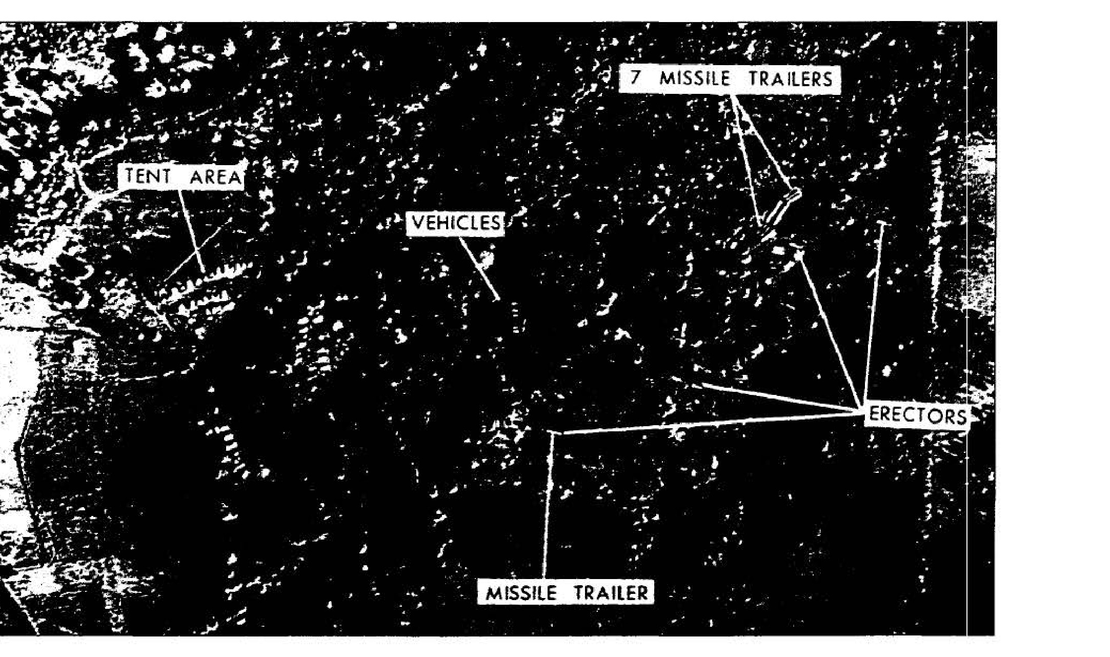
Soviet MRBM site in Cuba, 1 October 1962
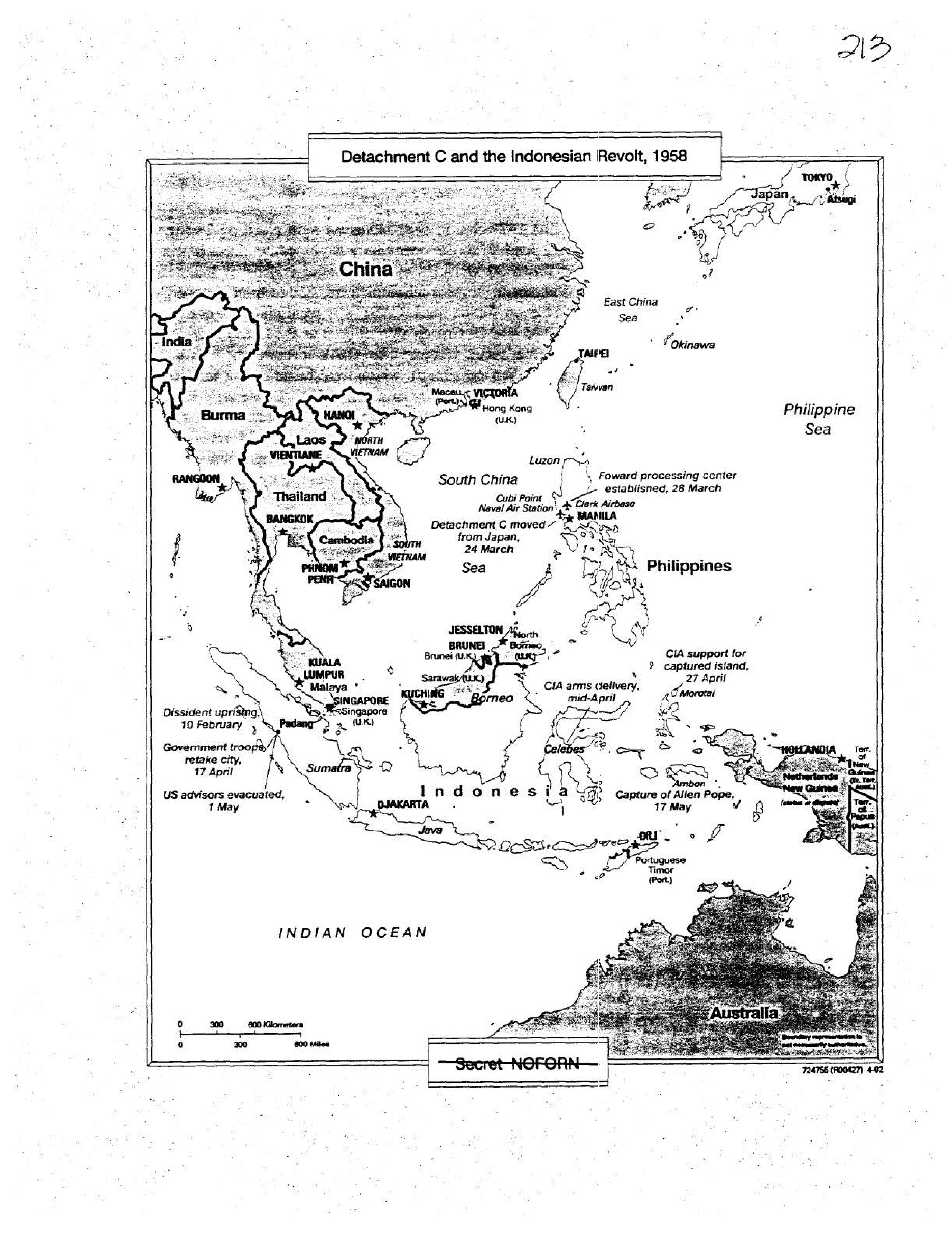
Detachment C and the Indonesian Revolt, 1958
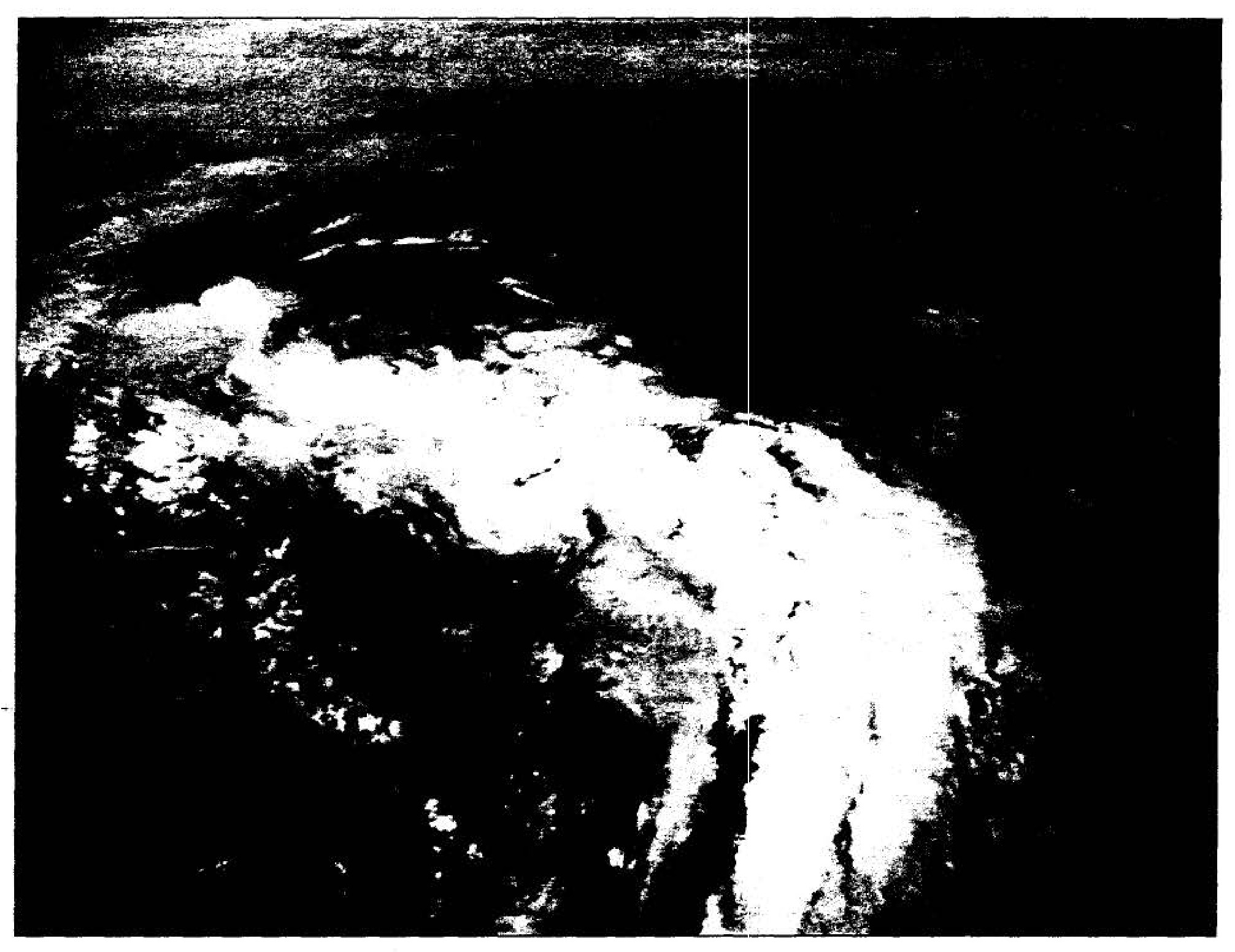
U-2 photography of Typhoon Winnie, July 1958
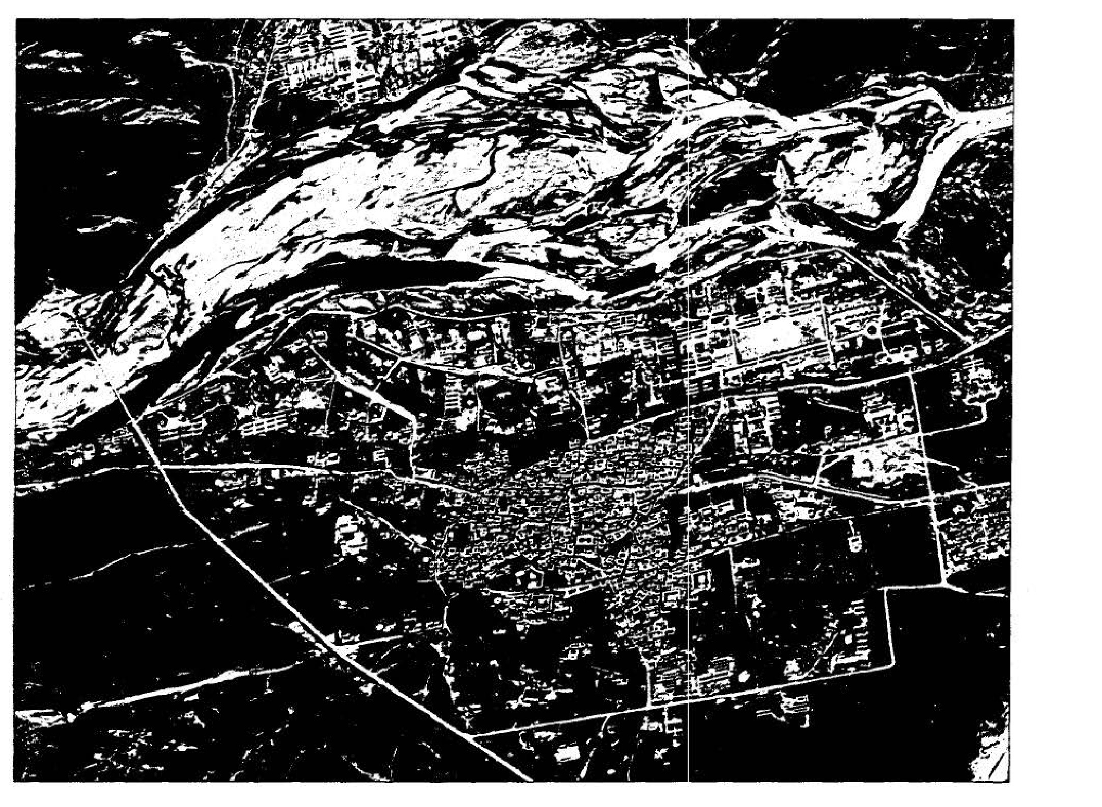
Lhasa, Tibet, November 1959
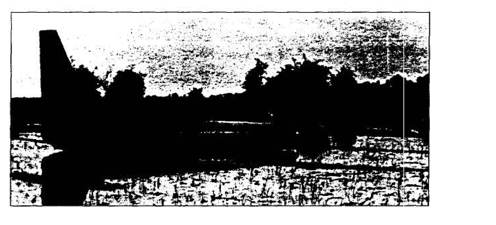
Recovery of Article 349, April 1960
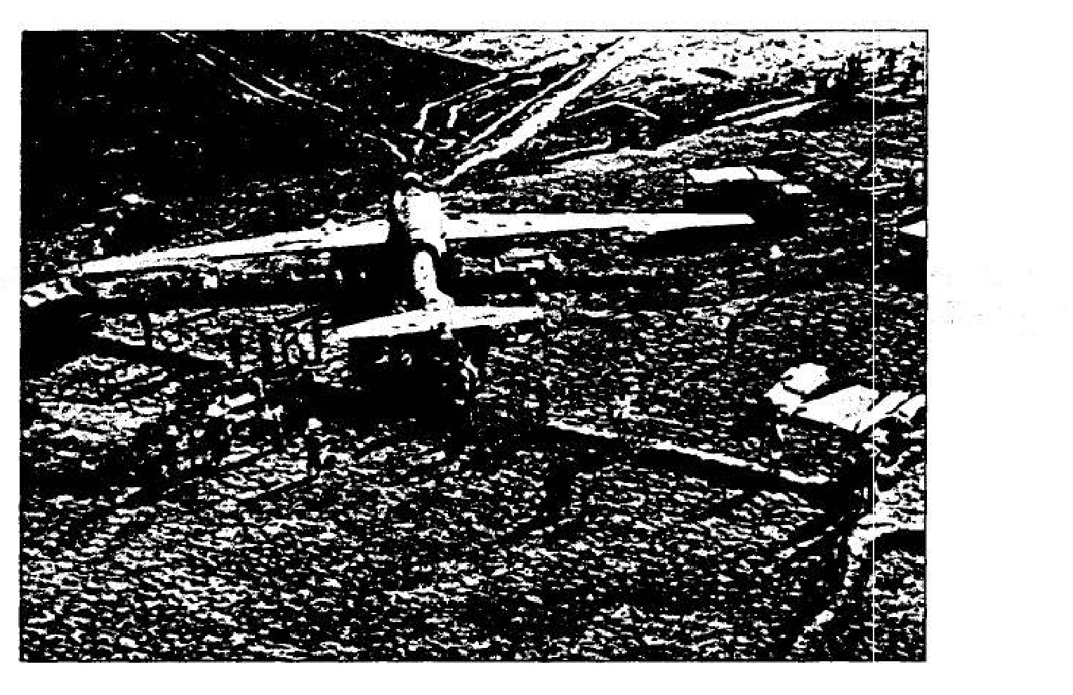
A helicopter lifts wreckage of a U-2.
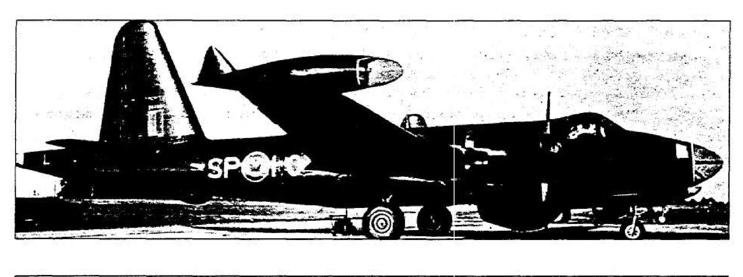
A Lockheed P-2V7 aircraft on a tarmac.
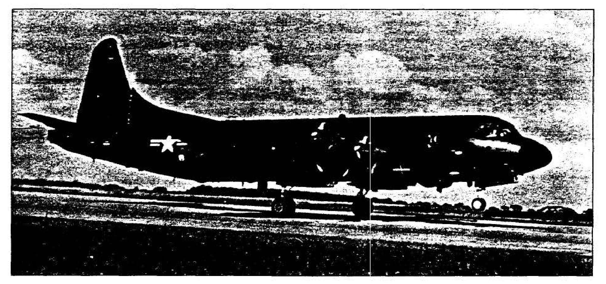
Lockheed P-2V7 and P3A reconnaissance aircraft
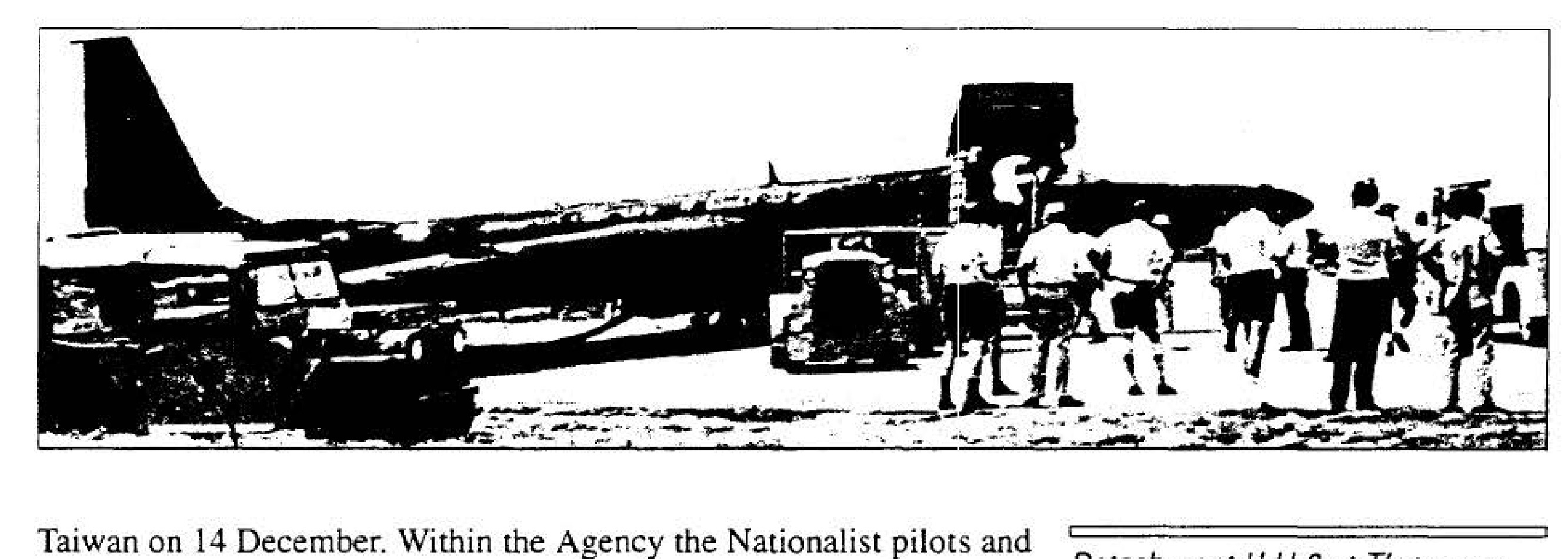
Detachment H U-2 at T'ao-yuan Airfield
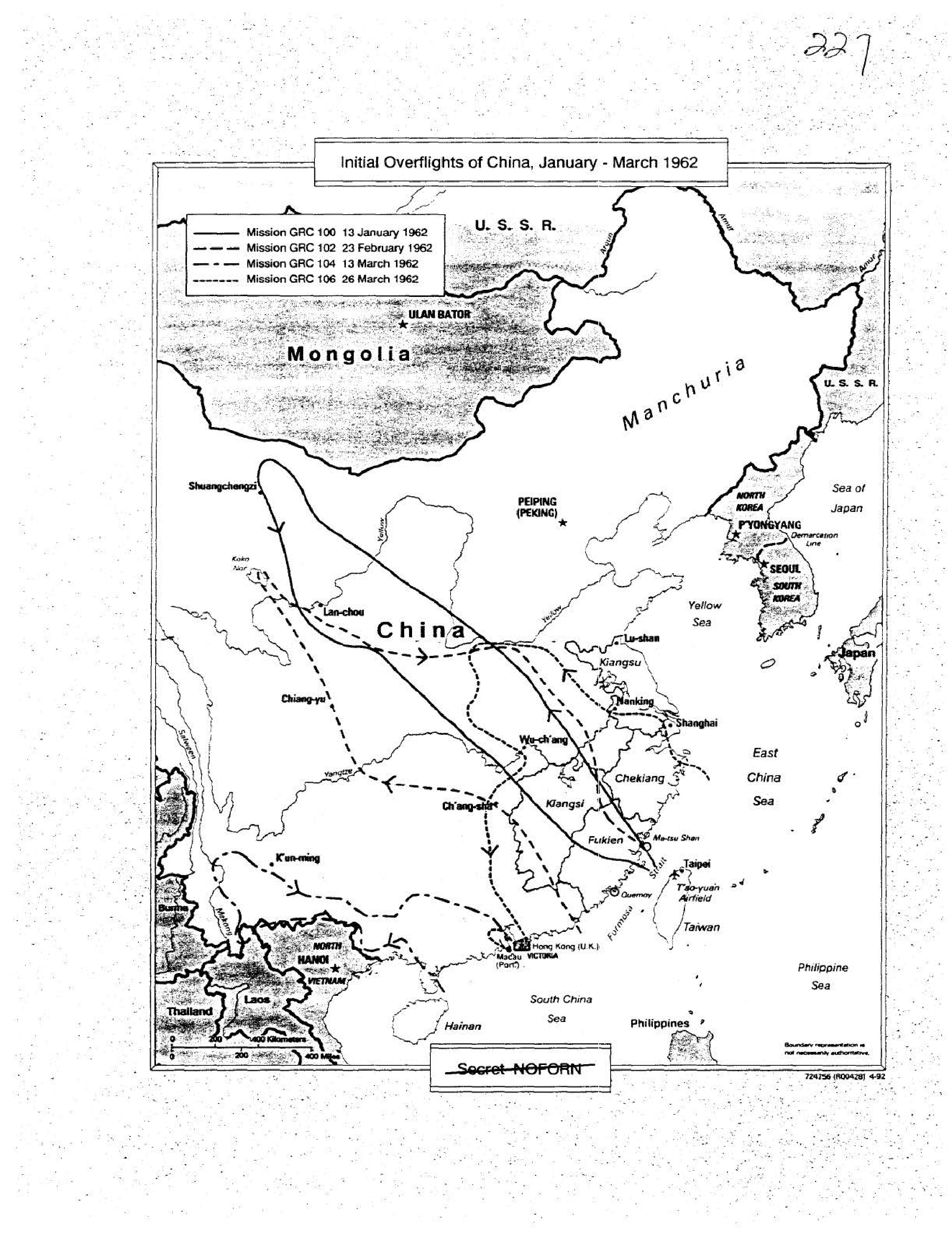
Initial Overflights of China, January - March 1962
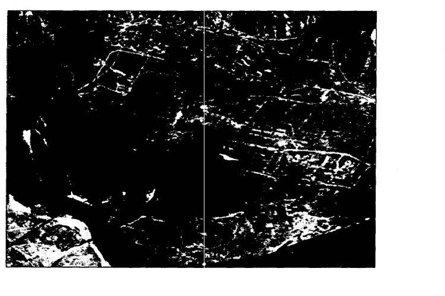
Lan-chou, PRC, 23 February 1962
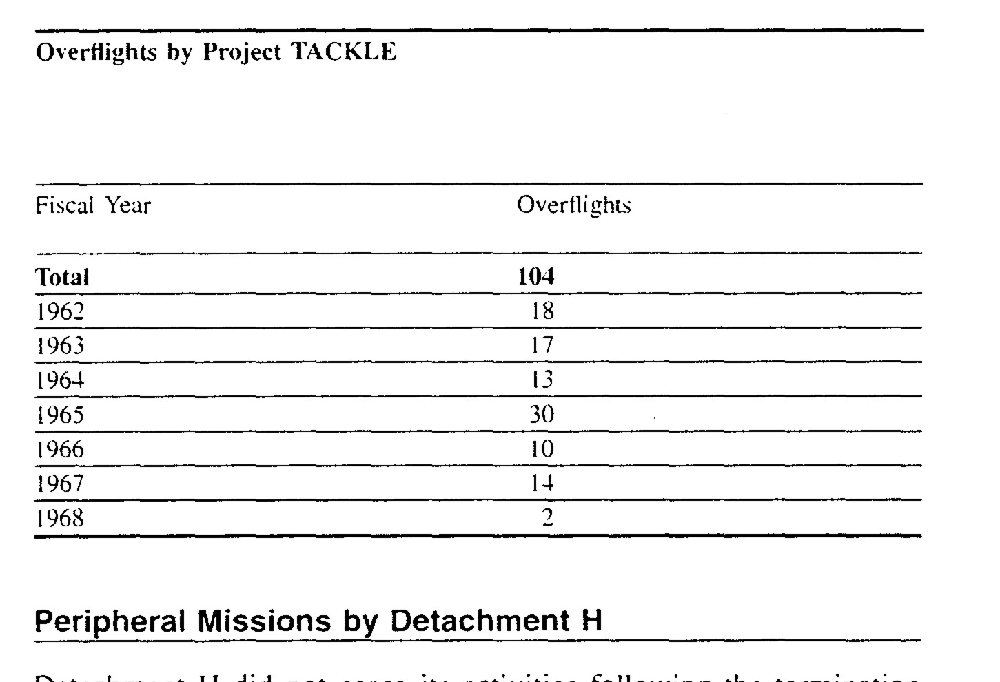
Overflights by Project TACKLE
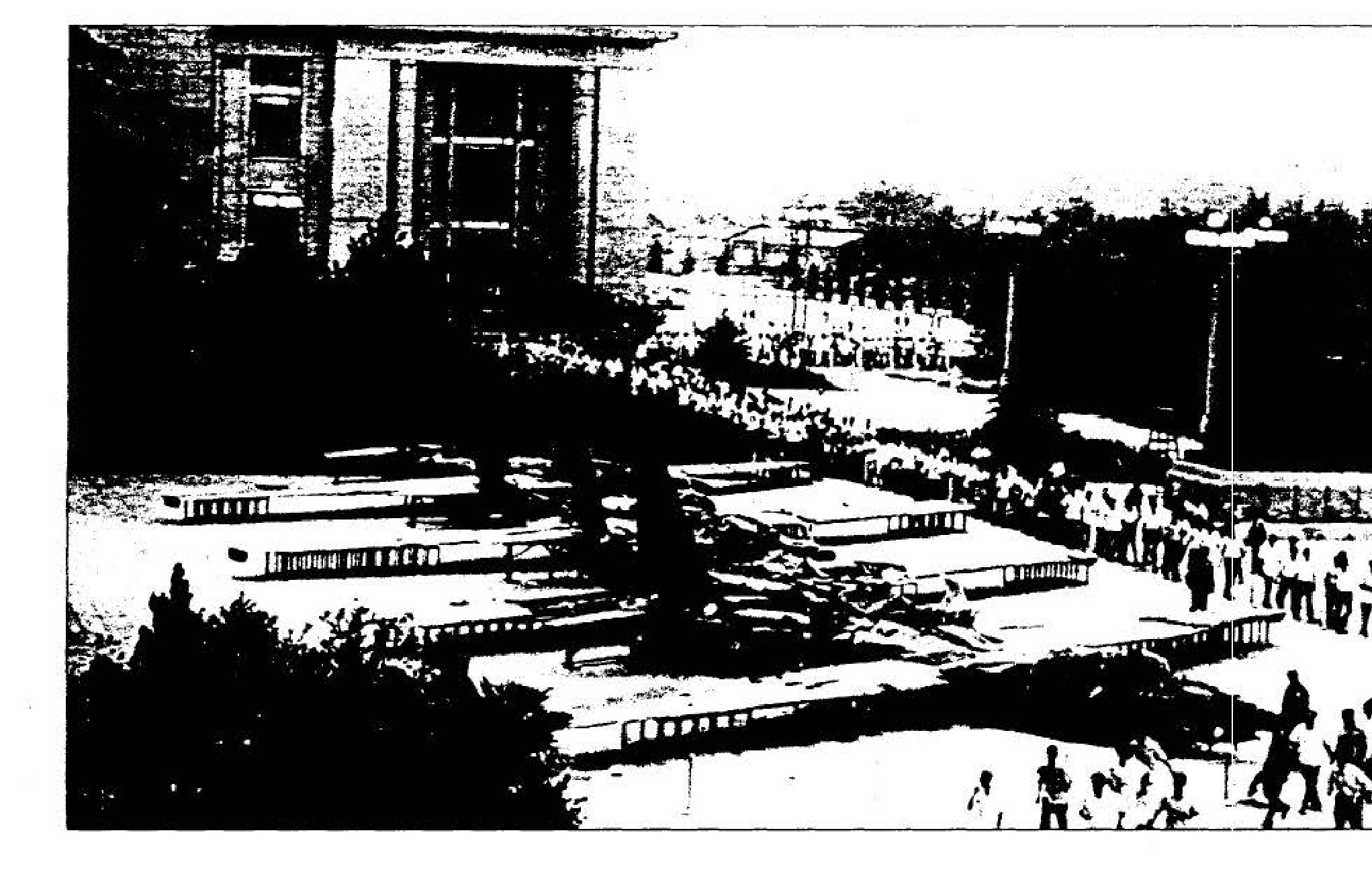
Display of downed detachment H U-2s in Peiping
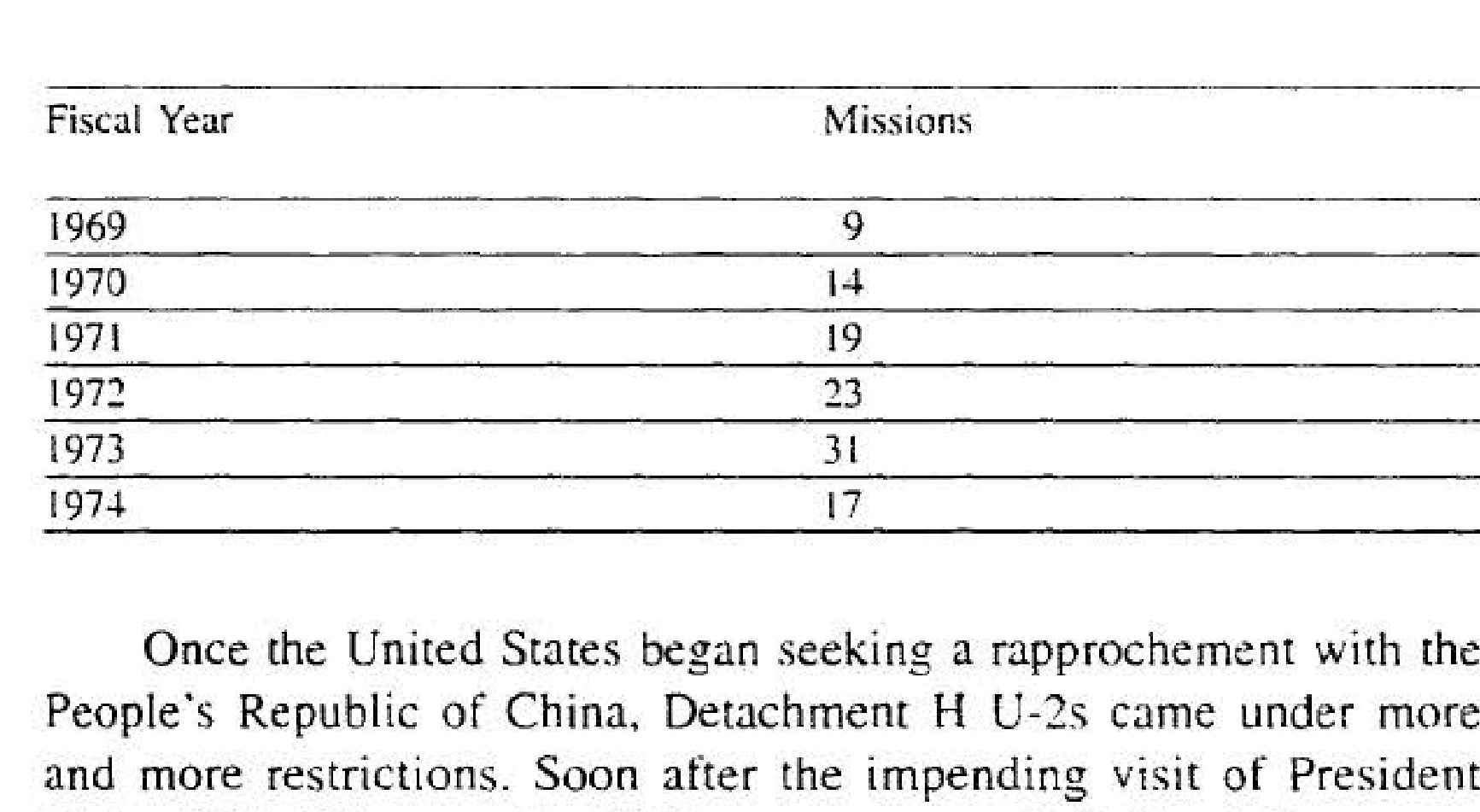
Project TACKLE Peripheral Missions, 1969-1974
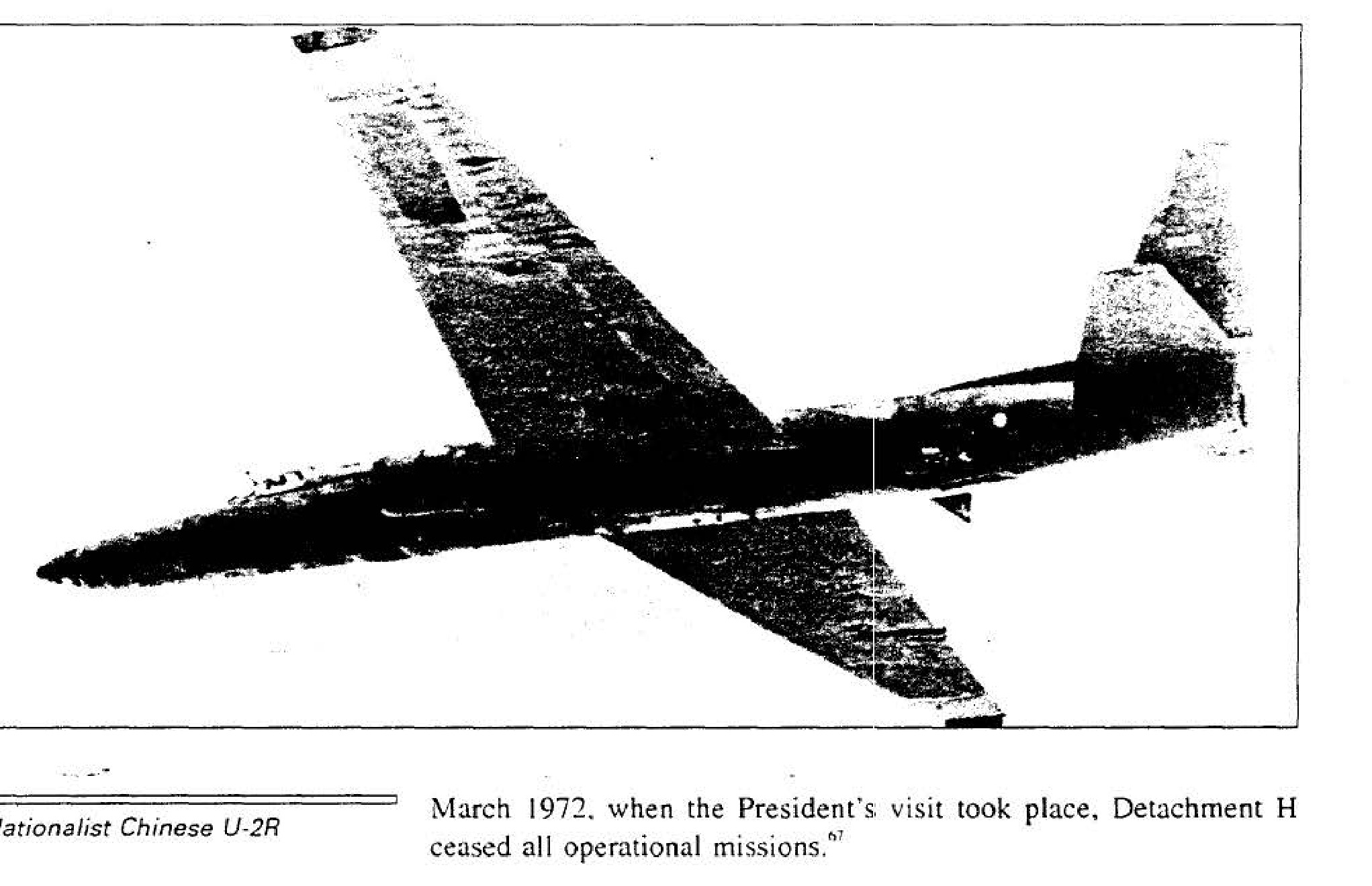
Nationalist Chinese U-2R
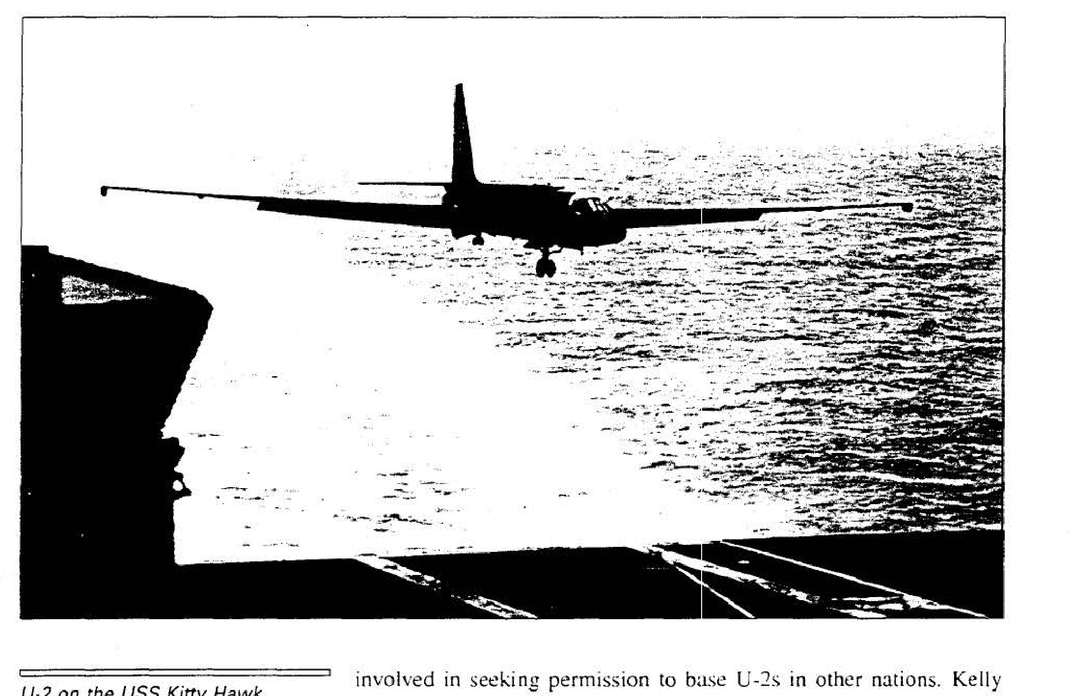
U-2 on the USS Kitty Hawk, 5 August 1963
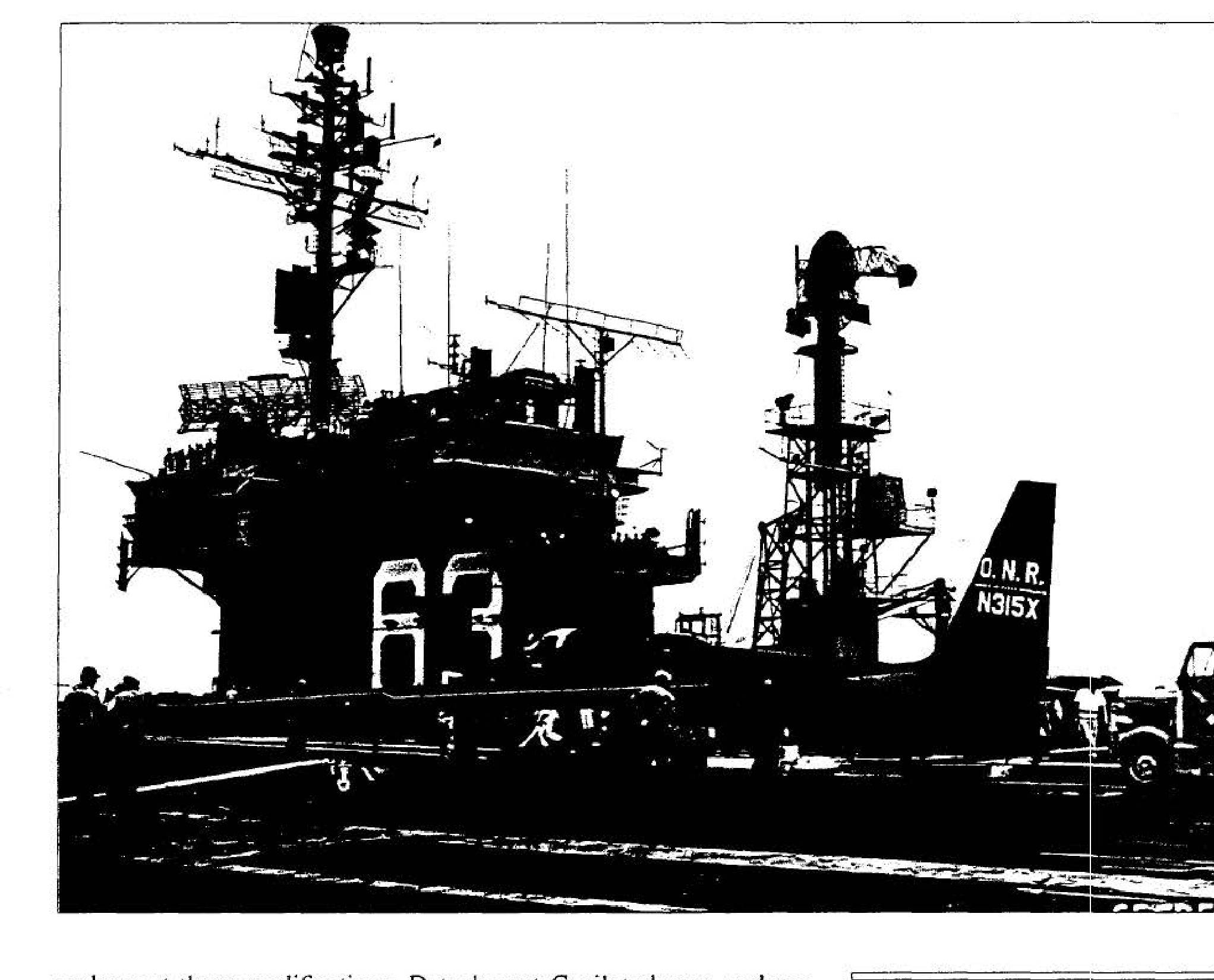
U-2 on the USS Kitty Hawk, 5 August 1963
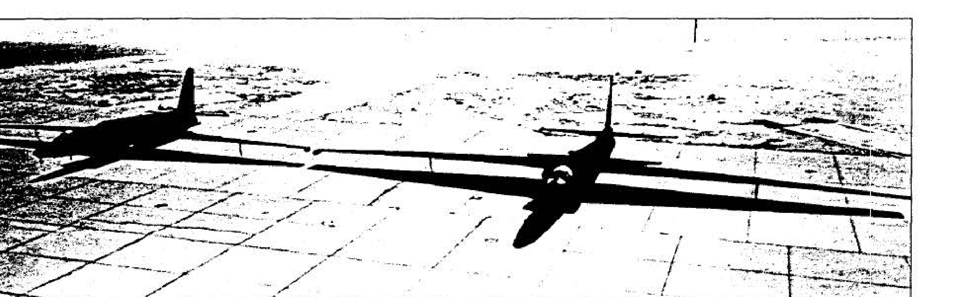
U-2C and U-2R
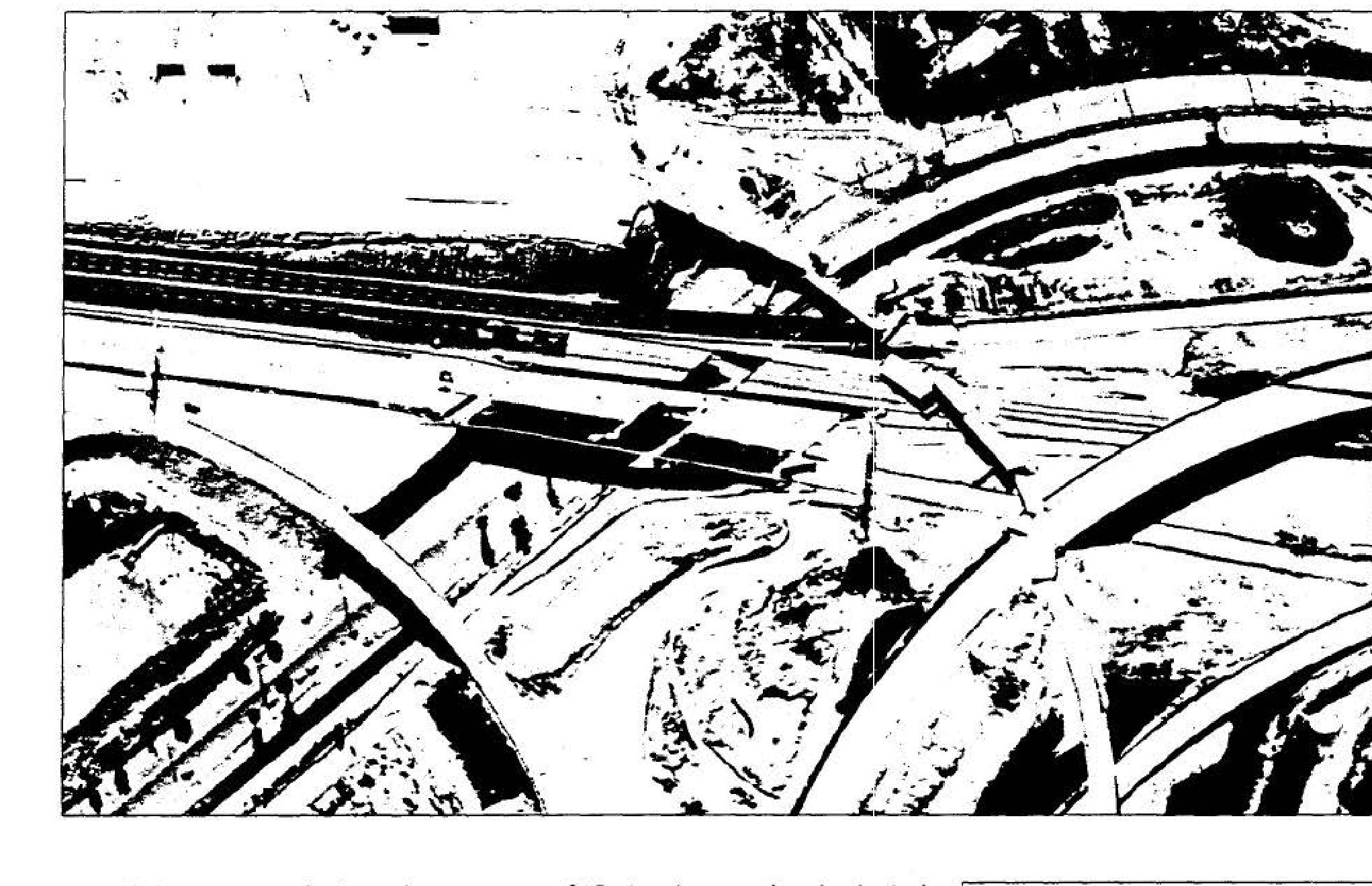
Earthquake damage, San Fernando Valley, 1971

CIA Project OXCART logo.
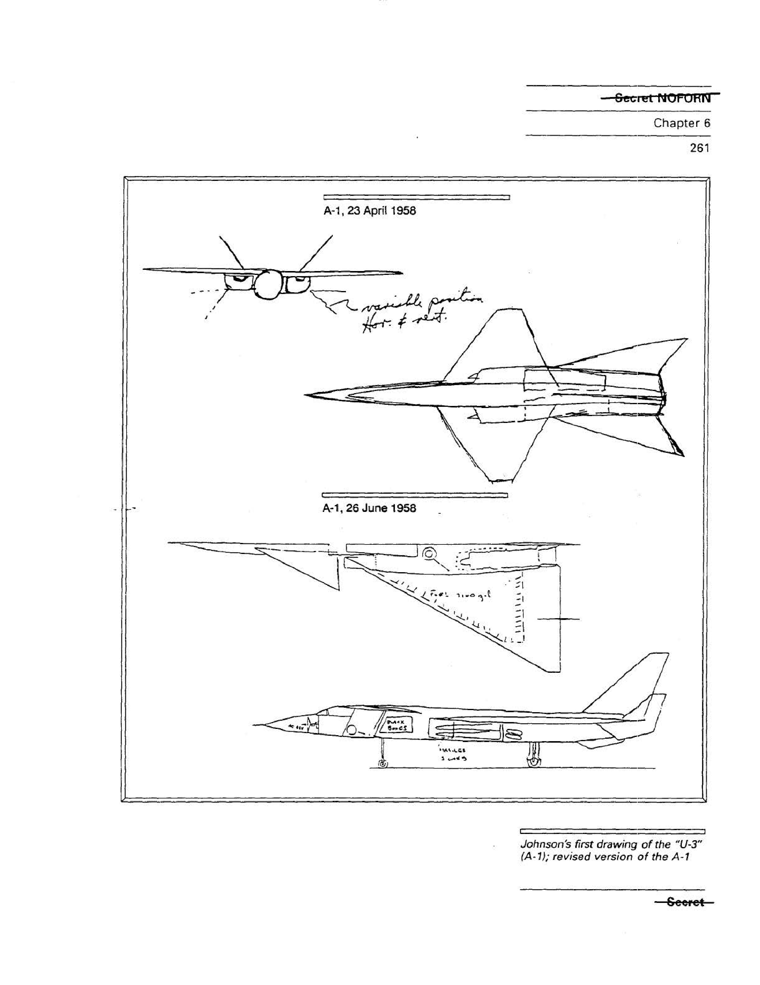
Sketches of the A-1 aircraft design from April and June 1958.
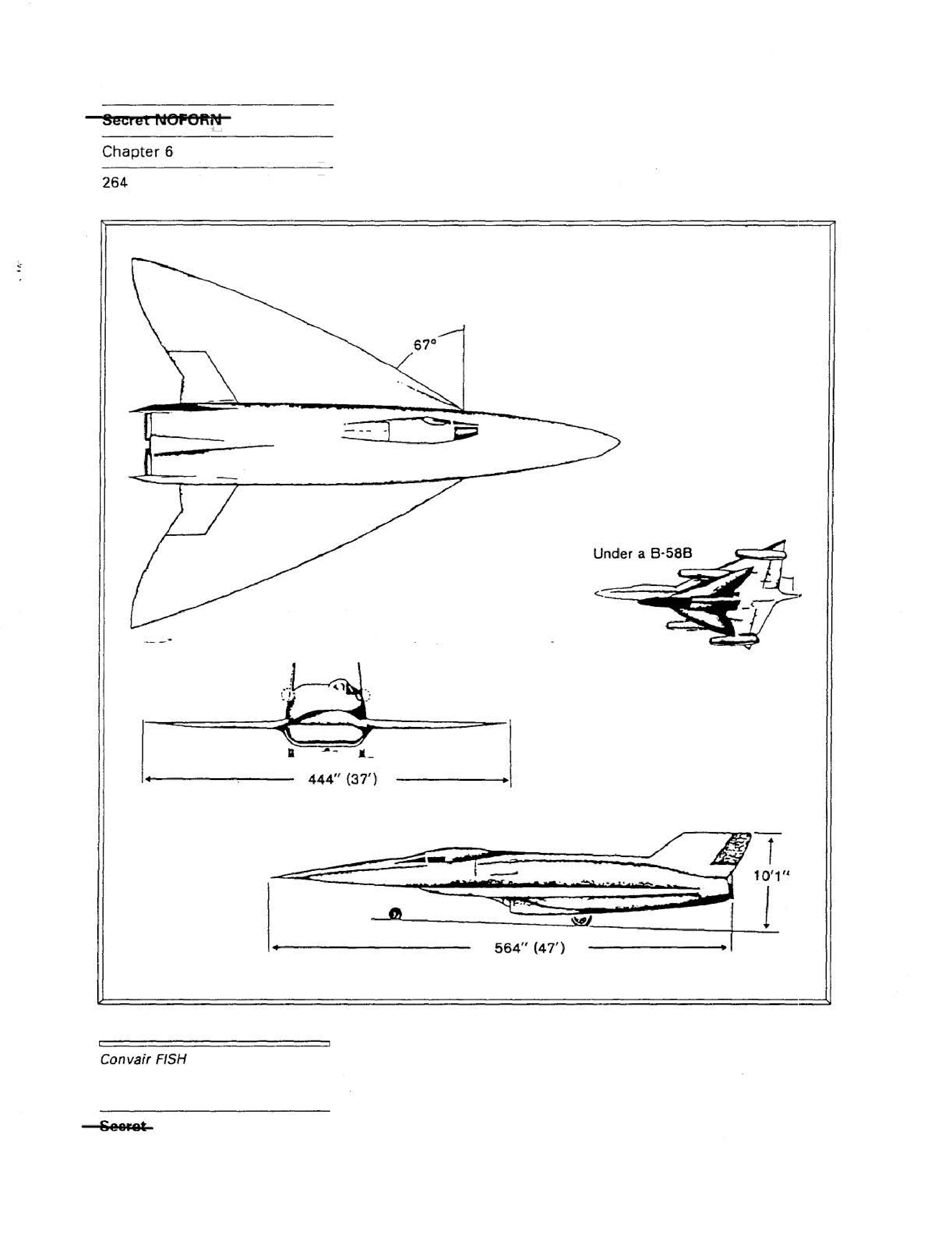
Diagrams of the Convair FISH aircraft, showing dimensions and its placement under a B-58B bomber.
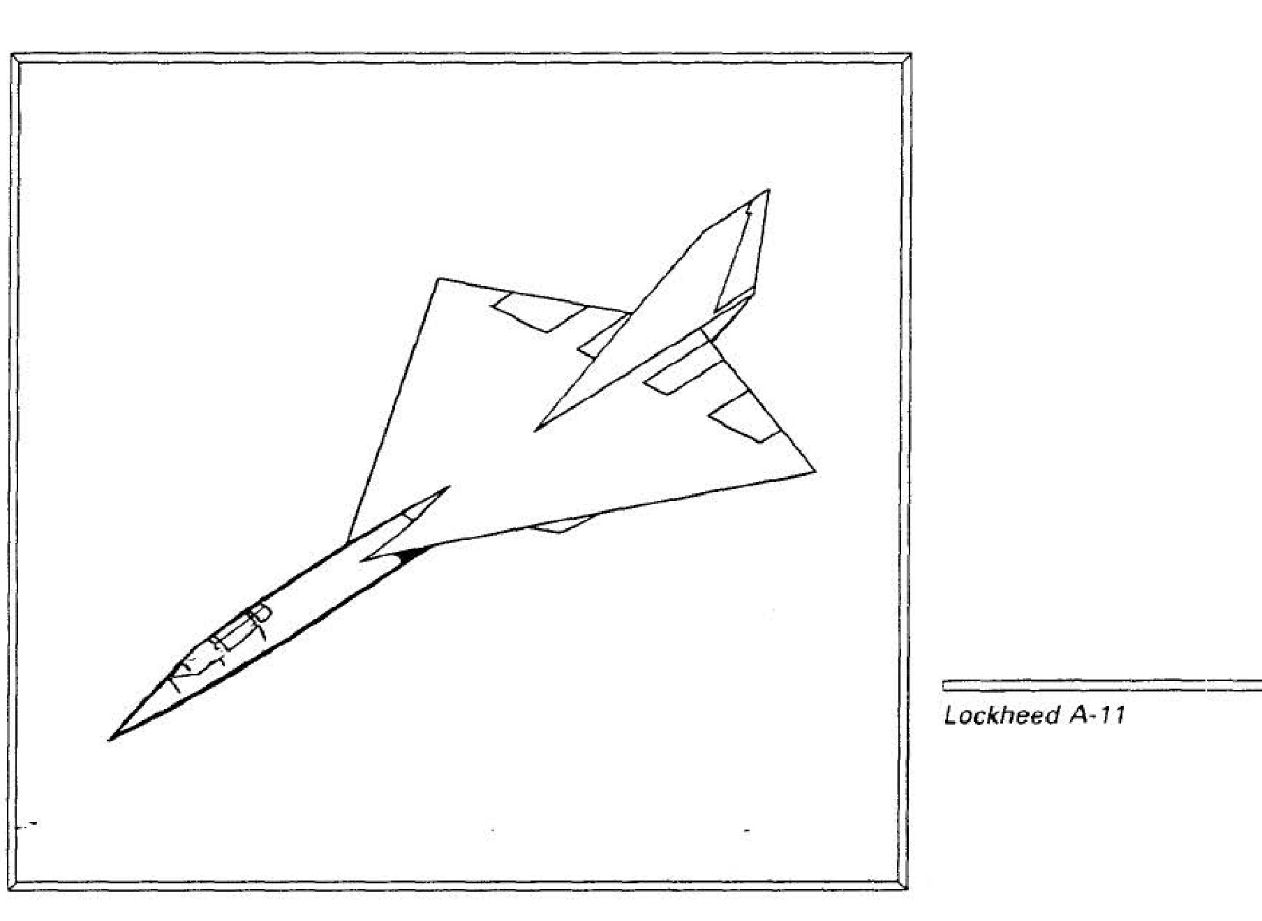
Lockheed A-11
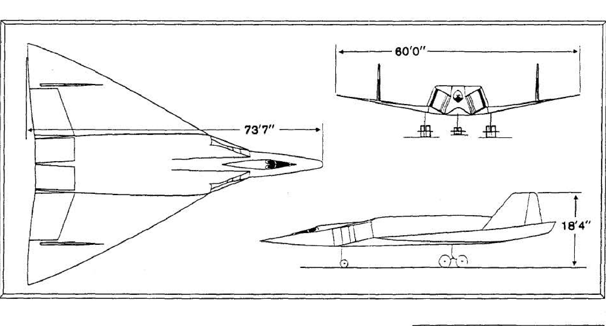
Diagram of the Convair KINGFISH aircraft with dimensions.
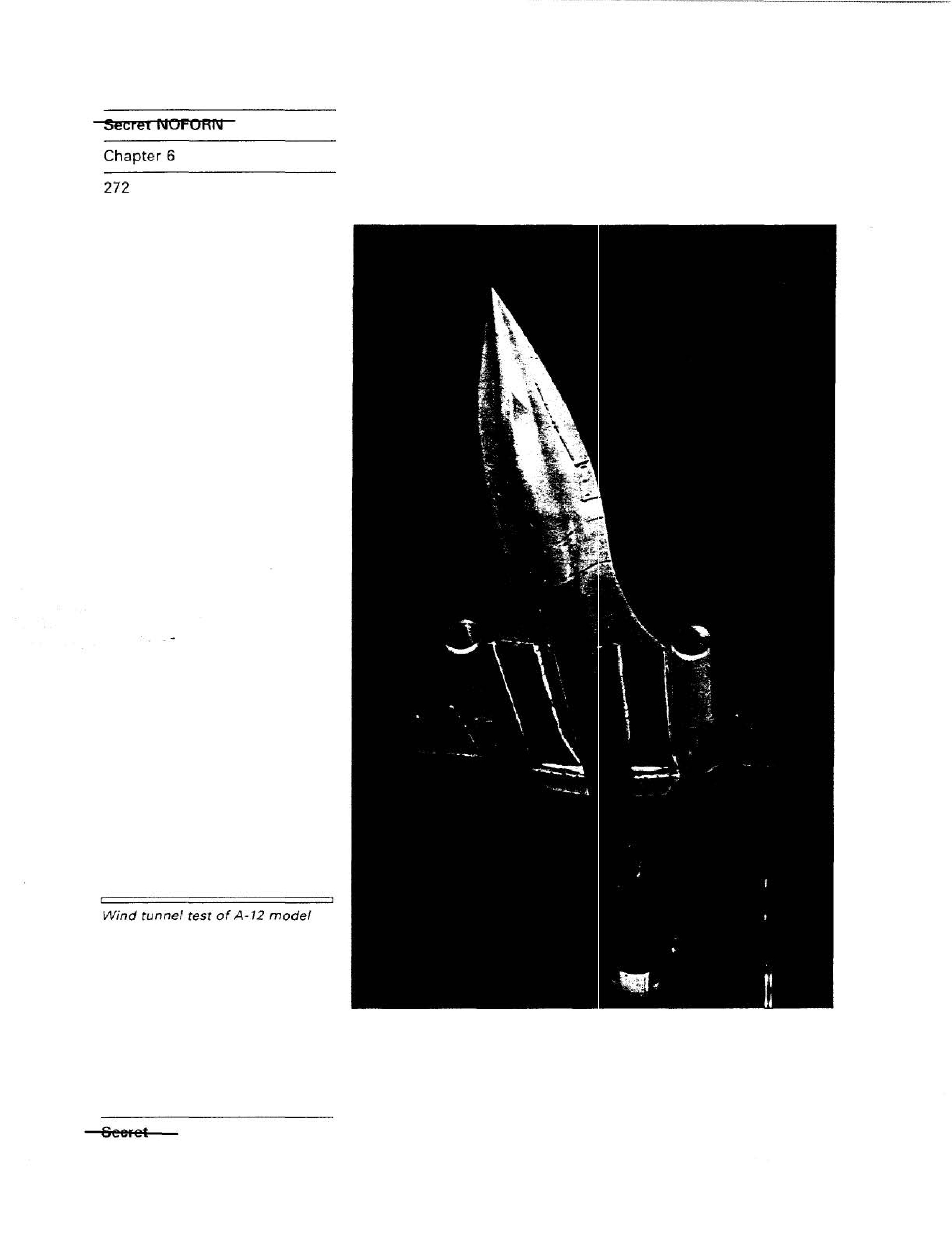
Wind tunnel test of A-12 model
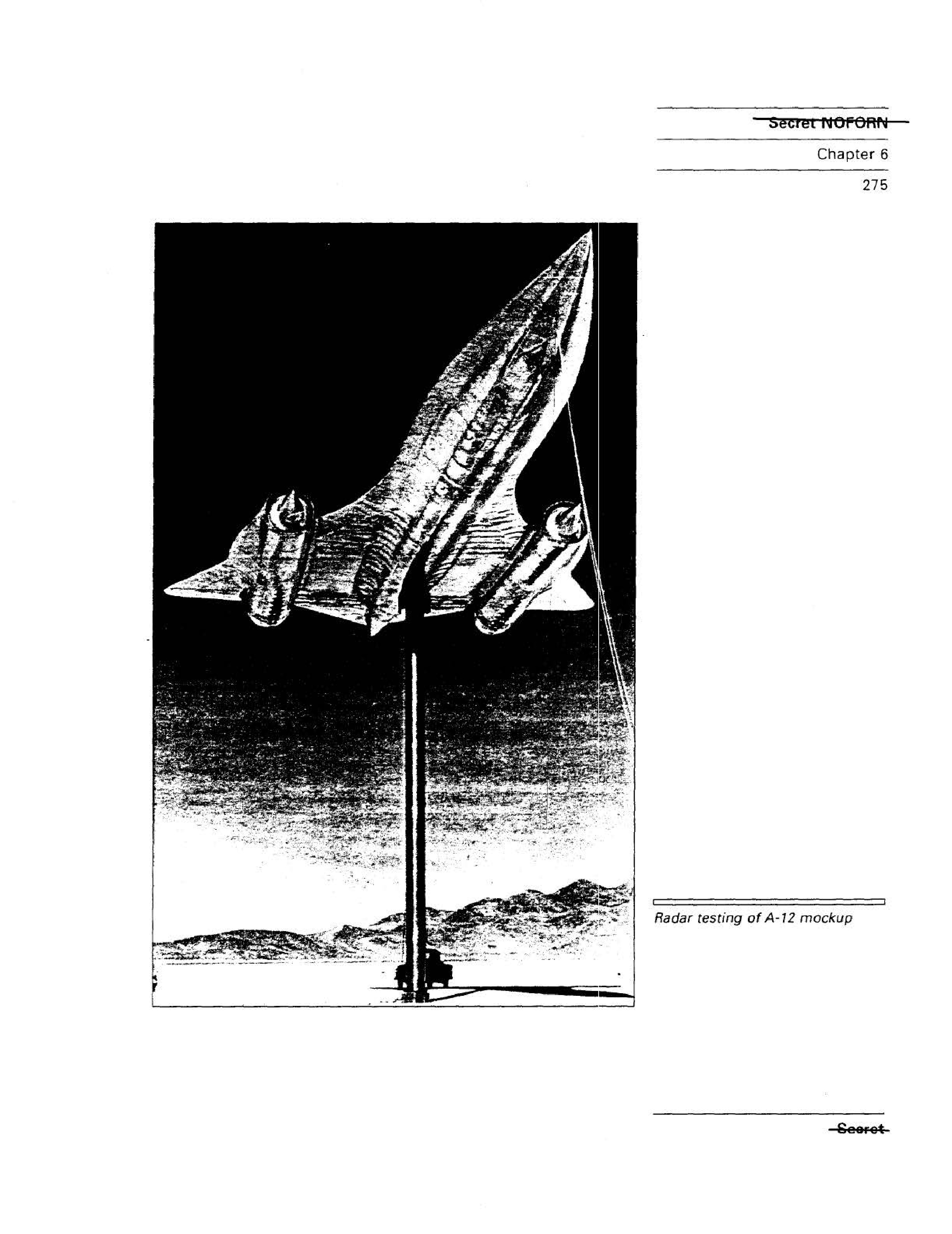
Radar testing of A-12 mockup
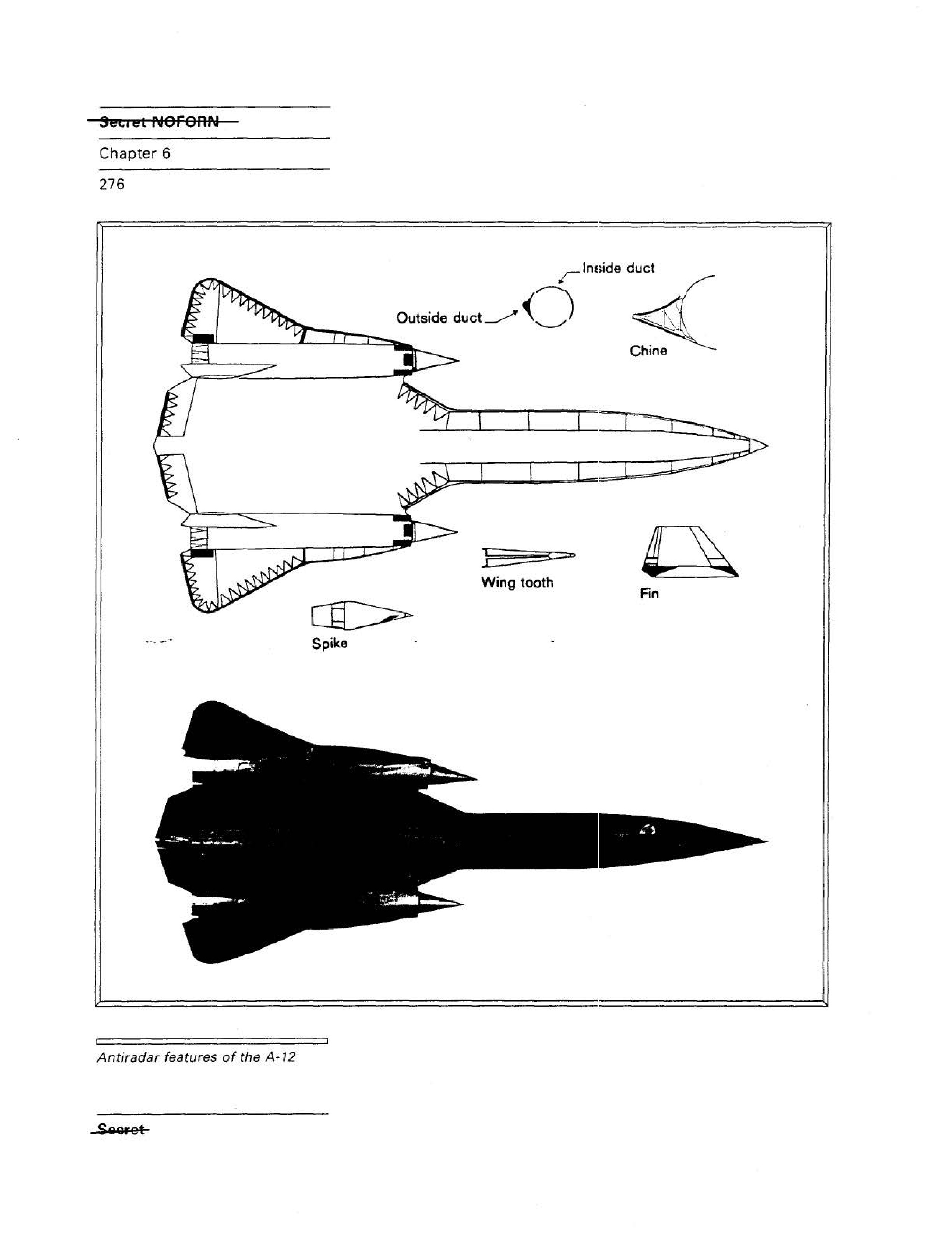
Antiradar features of the A-12
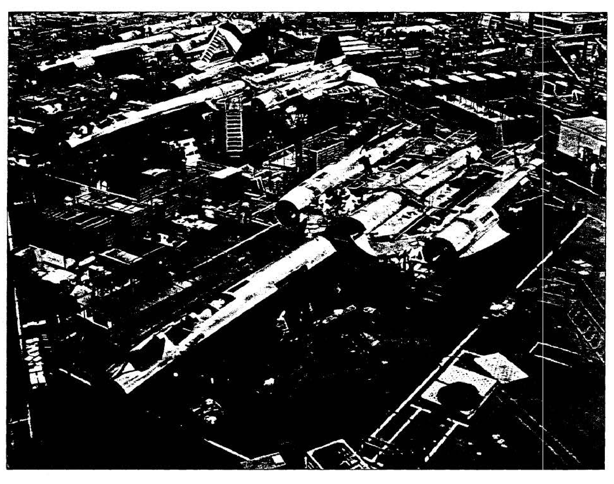
OXCART production facilities
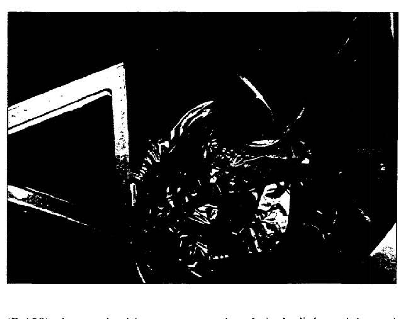
OXCART pilot suit
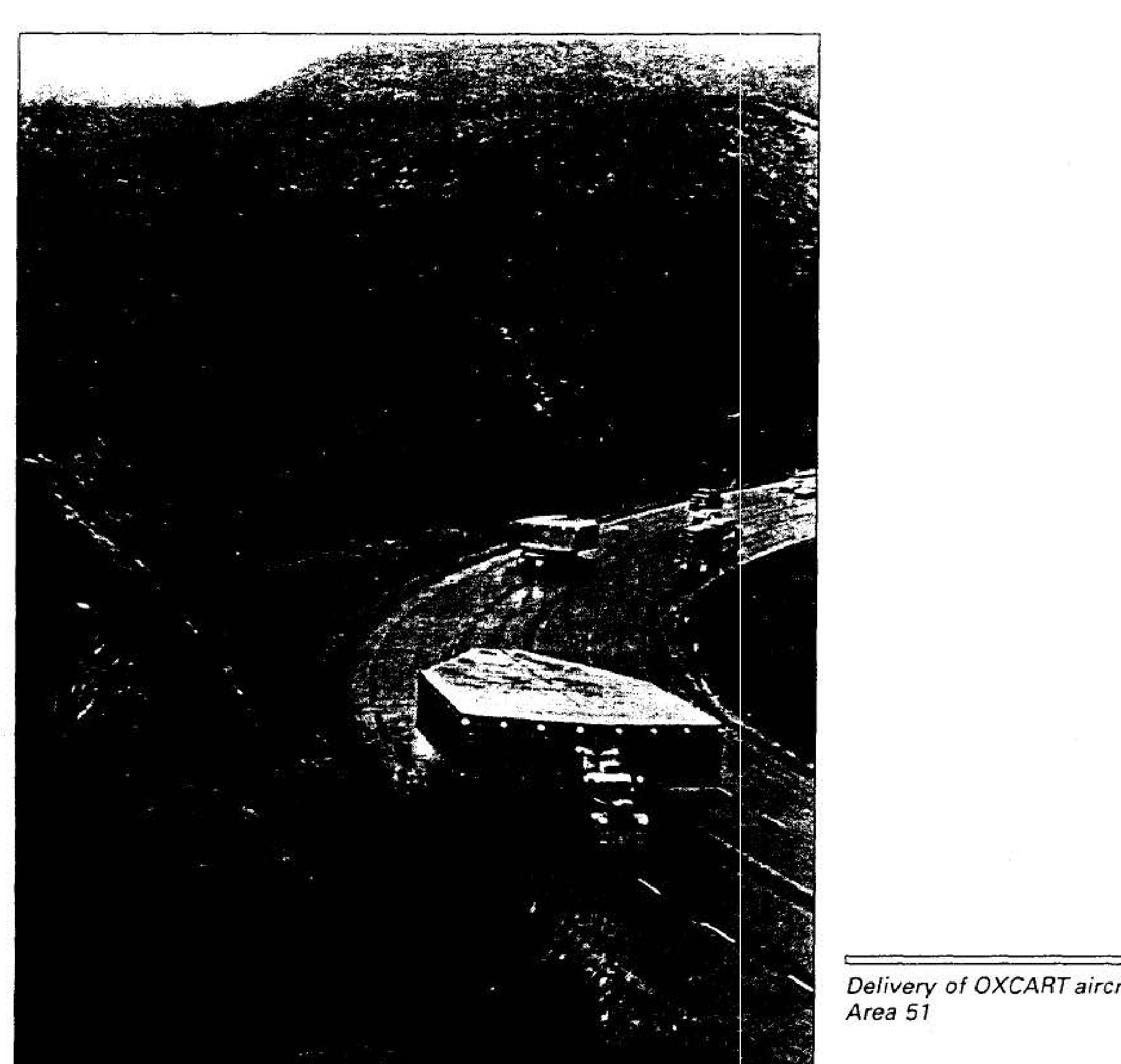
Delivery of OXCART aircraft to Area 51
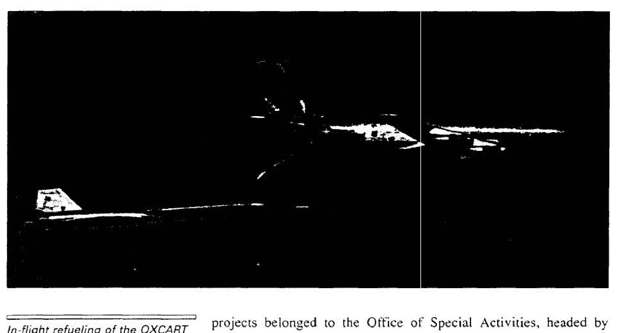
In-flight refueling of the OXCART
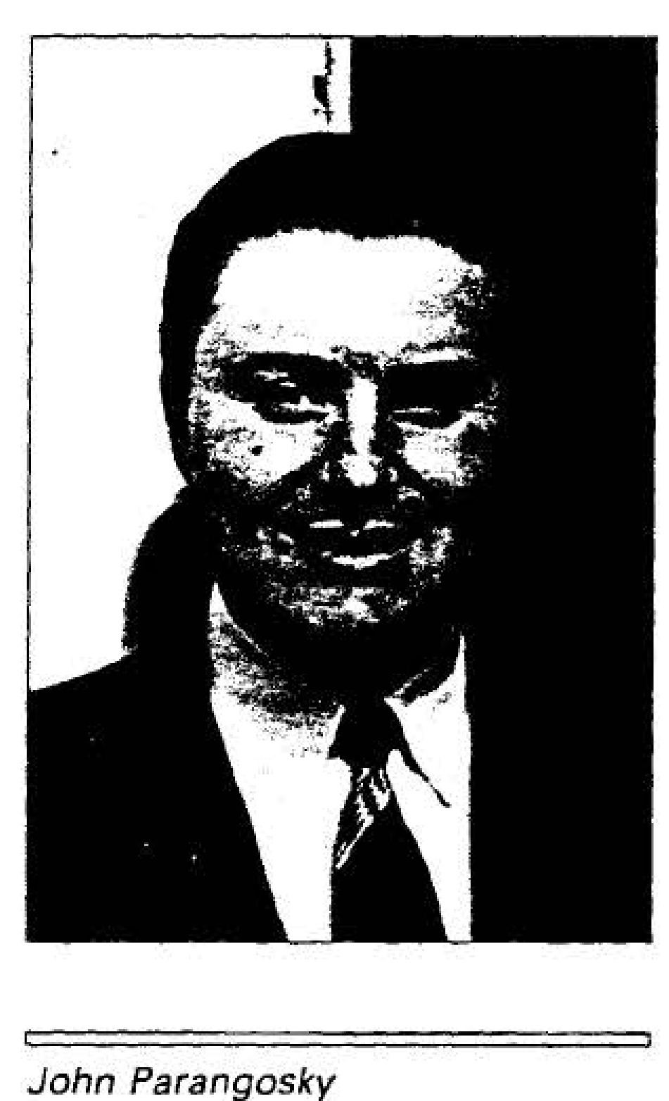
John Parangosky
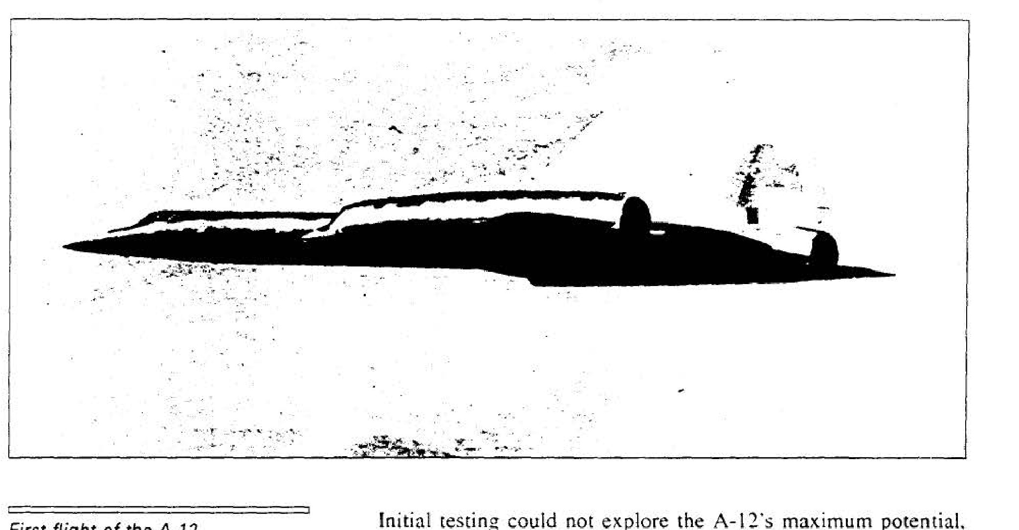
First flight of the A-12, 30 April 1962
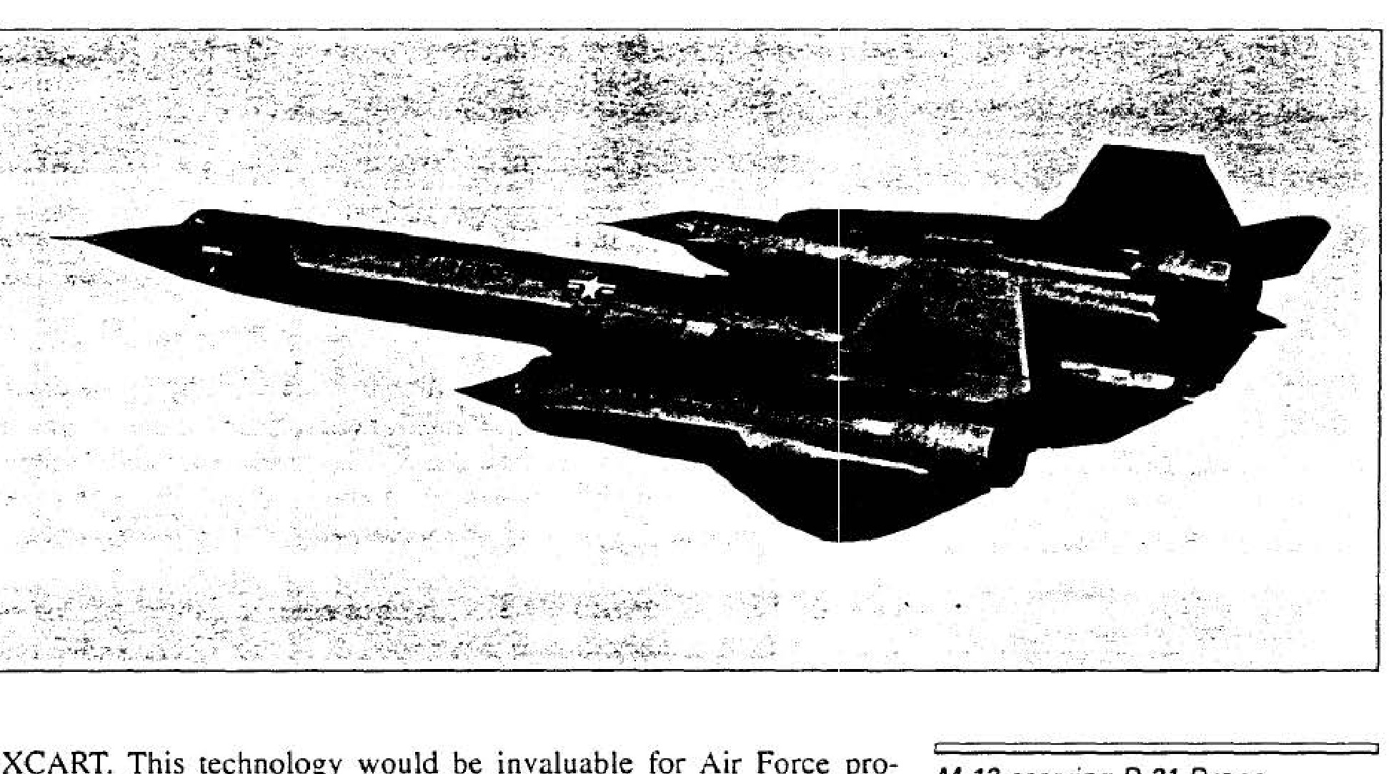
M-12 carrying D-21 Drone
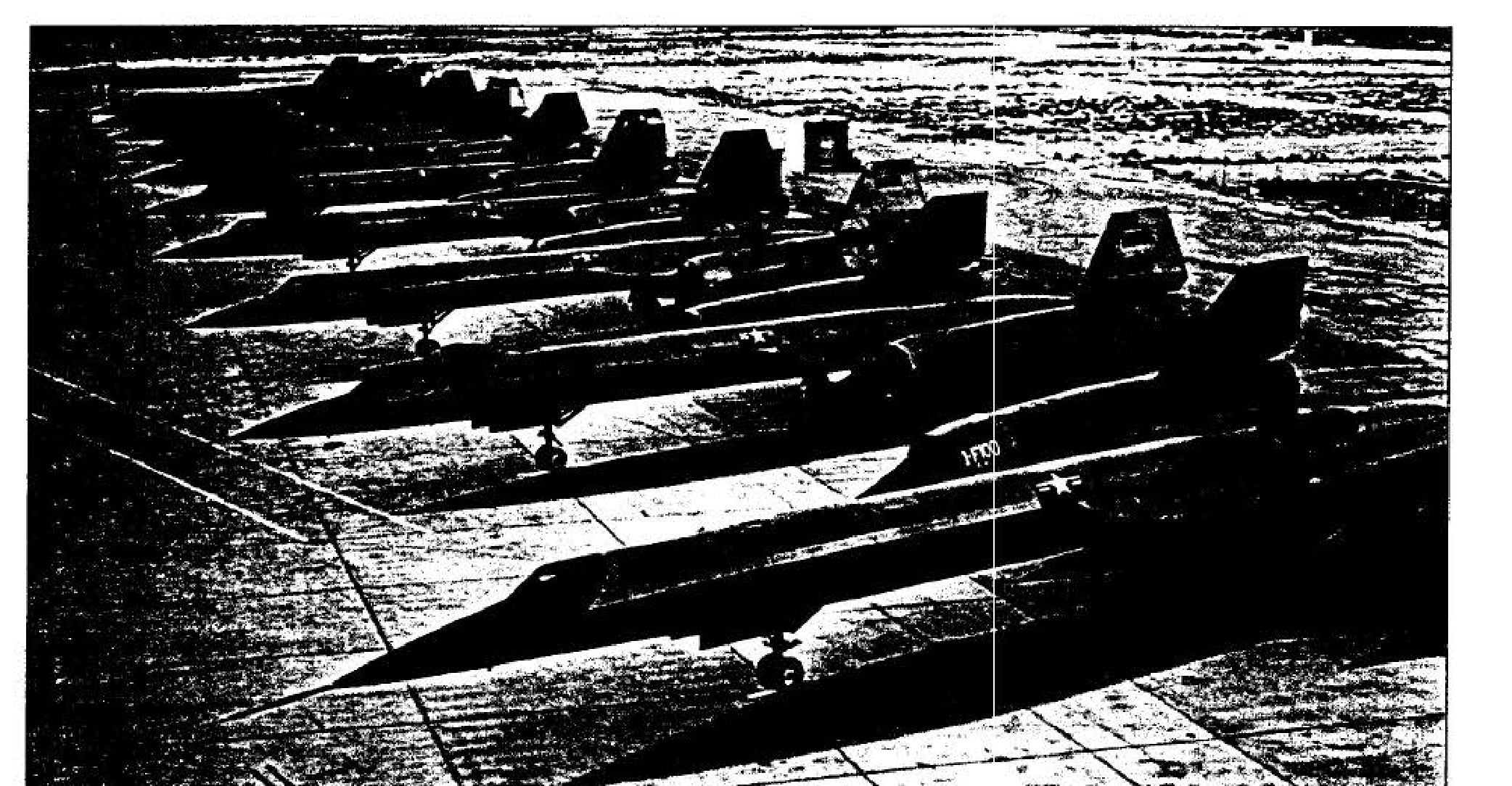
A-12s at Area 51
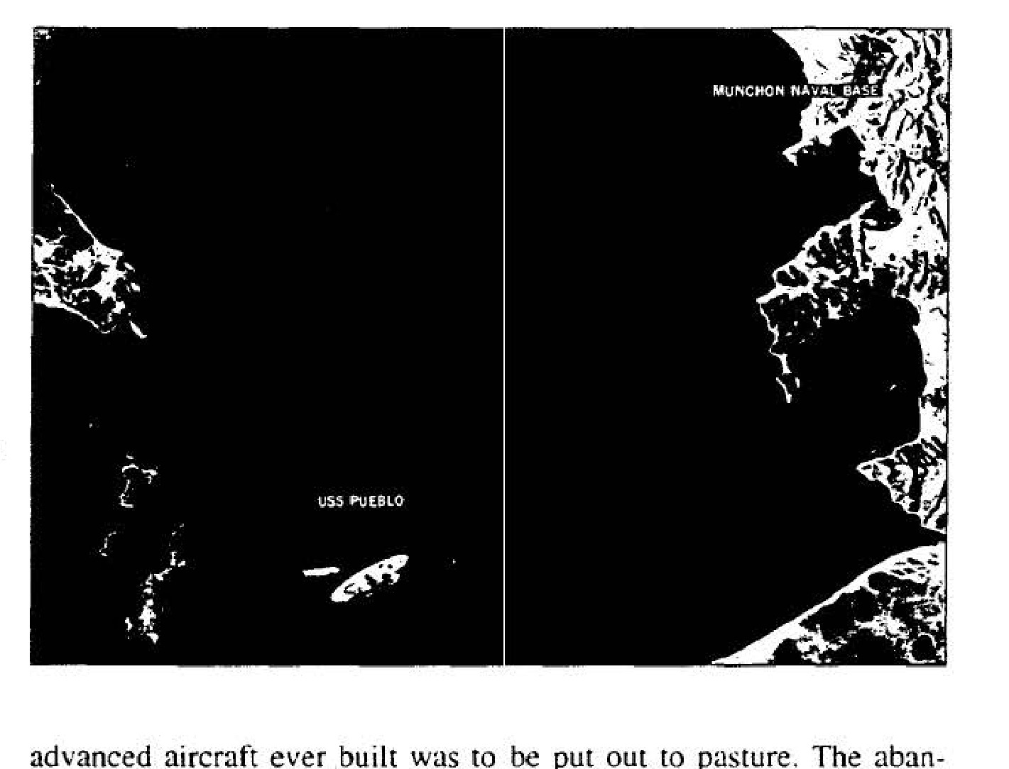
USS Pueblo in Wonsan Harbor
Initial storage arrangements for A-12s at Palmdale
Chapter 7 emblem
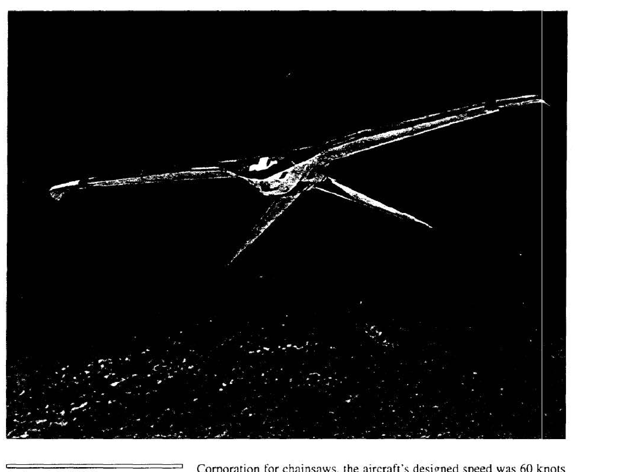
Project AQUILINE
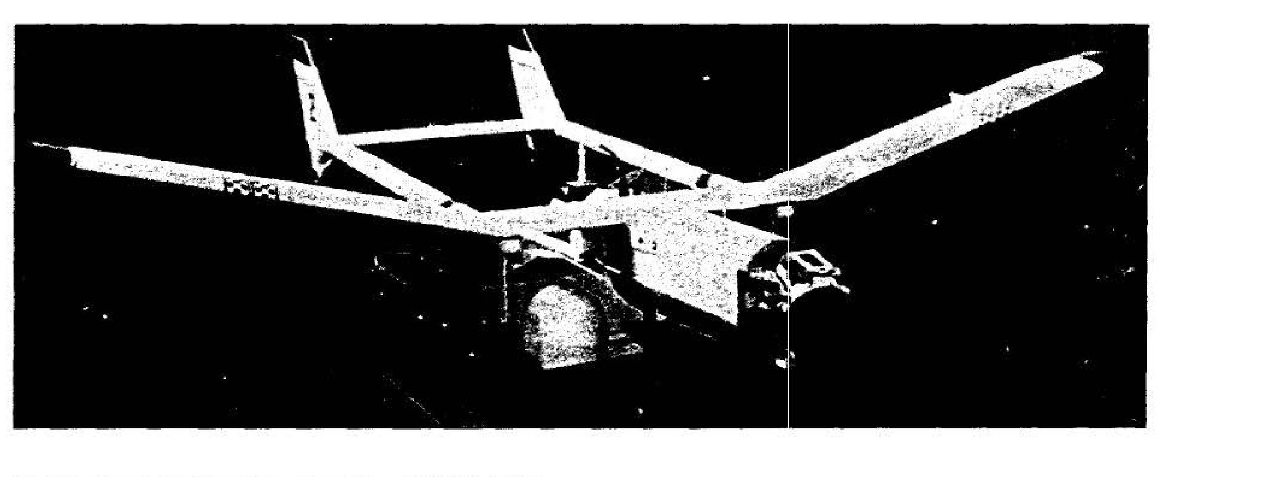
Project AXILLARY
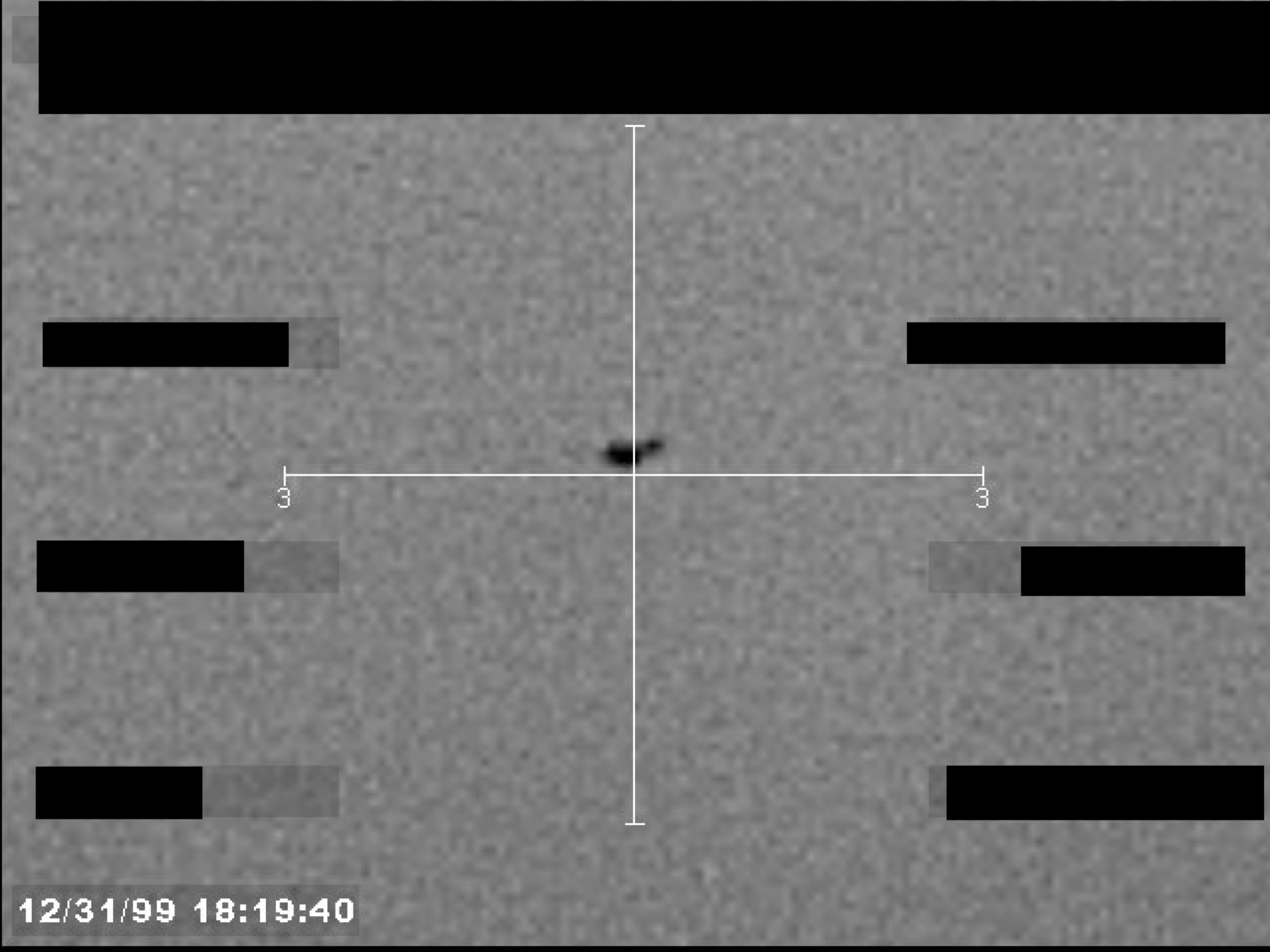
Sensor footage frame showing a small, dark object at the center of a crosshair.
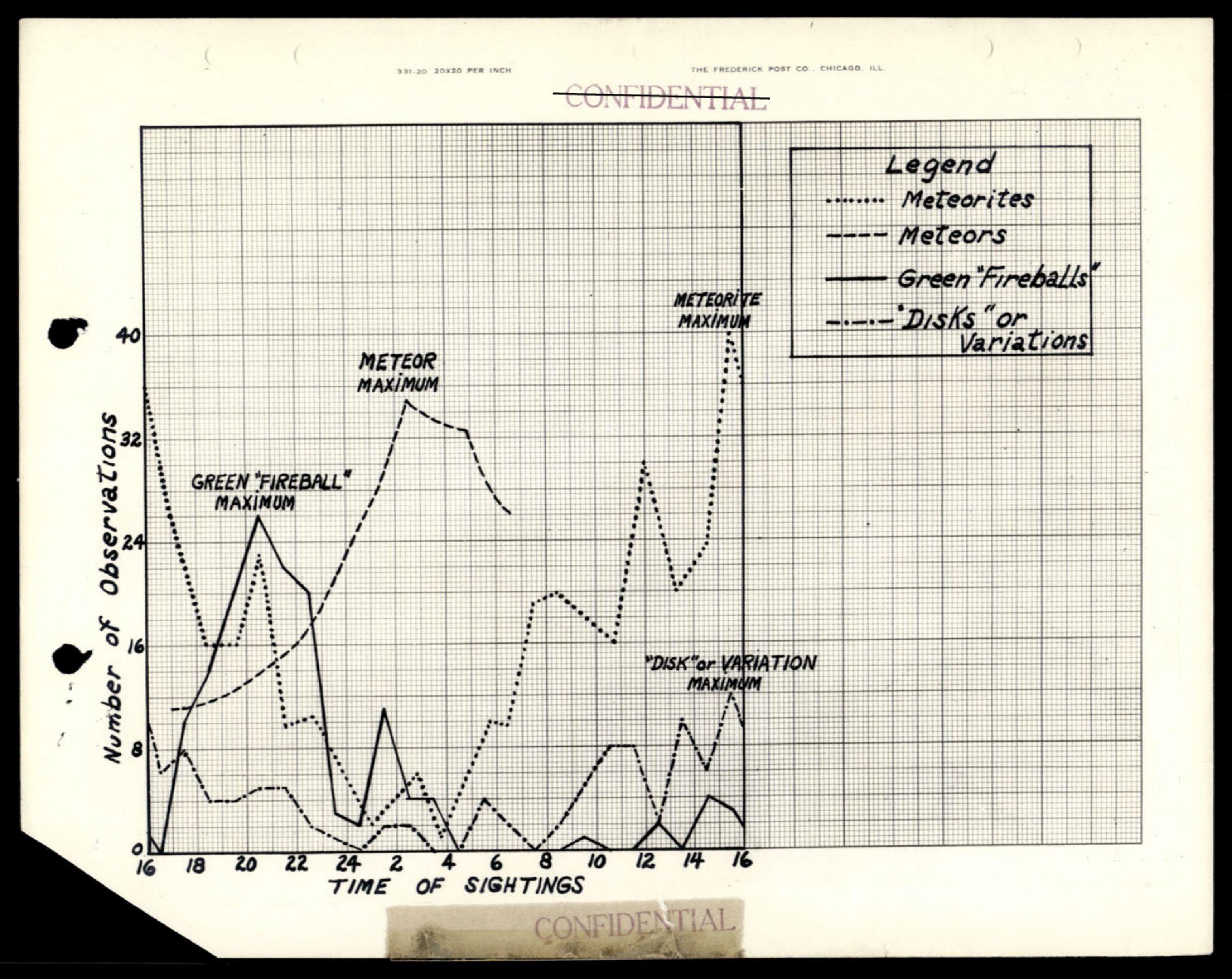
Graph showing Number of Observations vs Time of Sightings, with legend indicating Meteorites, Meteors, Green Fireballs, and Disks or Variations; peaks labeled as GREEN FIREBALL MAXIMUM, METEOR MAXIMUM, METEORITE MAXIMUM, and DISC VARIATION MAXIMUM
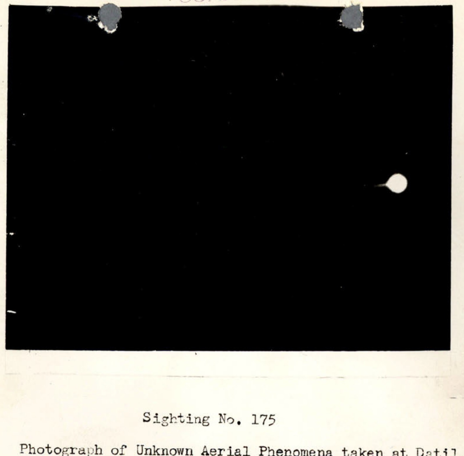
Photograph of Unknown Aerial Phenomena showing luminous object against dark sky

ABC Television advertisement showing Saturday programming with three circular plate images containing portraits of performers, silverware illustrations, and promotional text for Romance, Comedy, and Drama shows
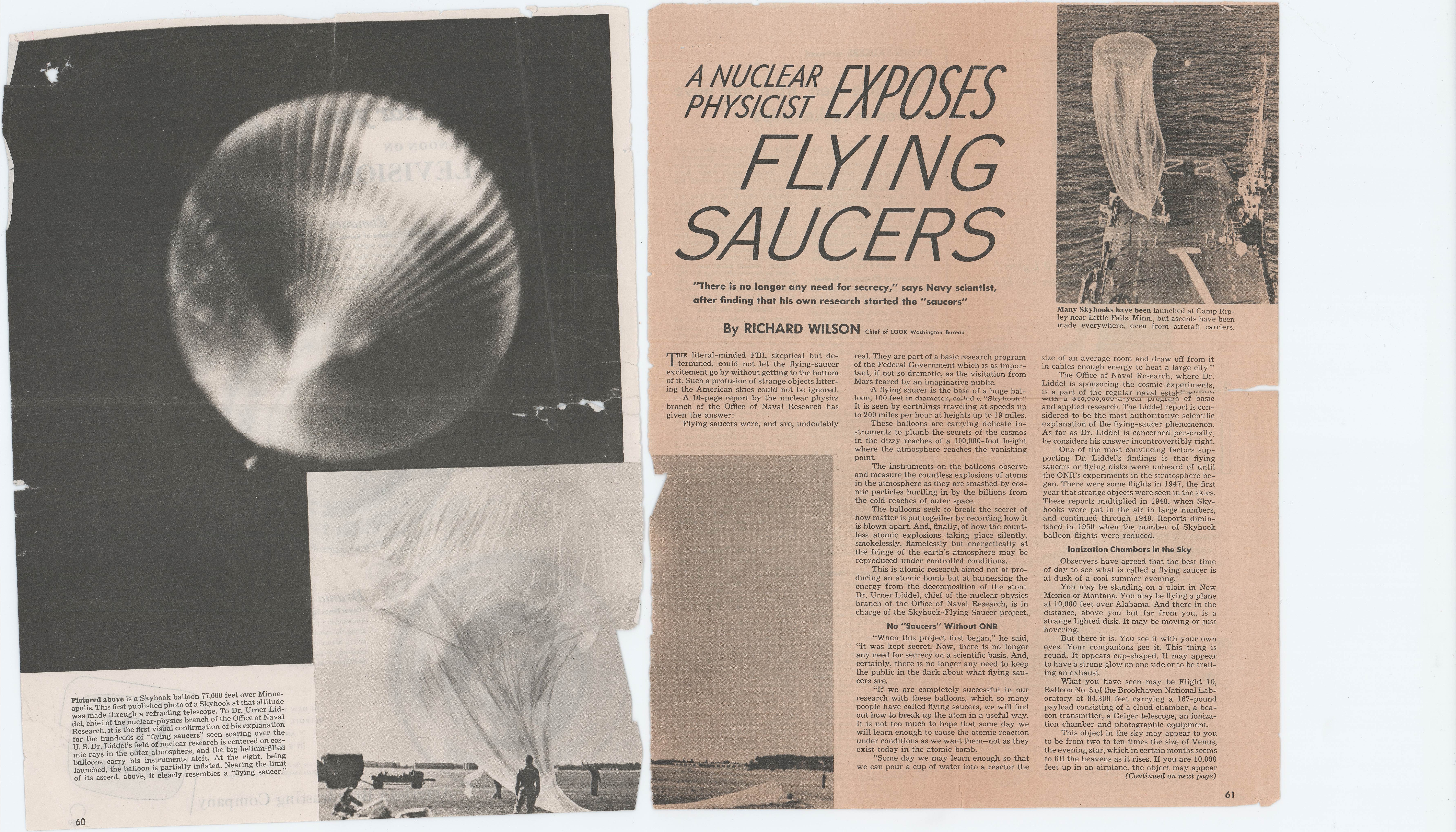
Skyhook balloon 77,000 feet over Minneapolis photographed through special camera
King whisky advertisement showing glass with ice and product bottle
Greyhound bus travel advertisement showing multiple family scenes and bus travel
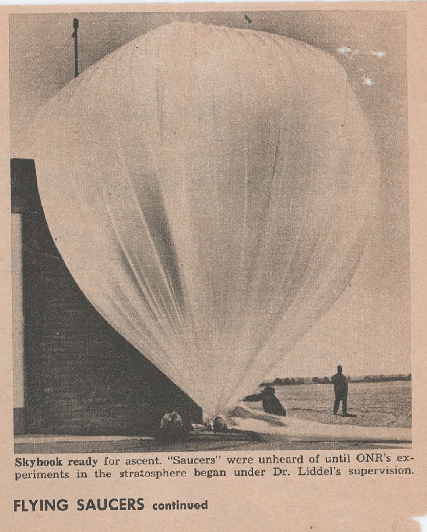
Skyhook ready for ascent
Freight train locomotive illustration

Freight train cars illustration
Freight train tank and cargo cars illustration

Freight train boxcars illustration

Freight train cars illustration
Department of the Air Force seal
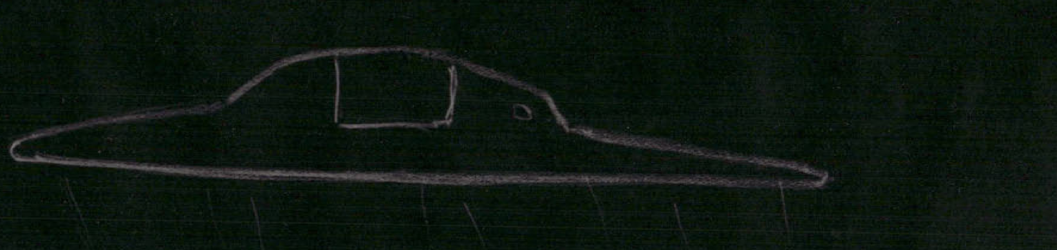
Hand-drawn sketch of disc-shaped object with dome or cabin structure on top
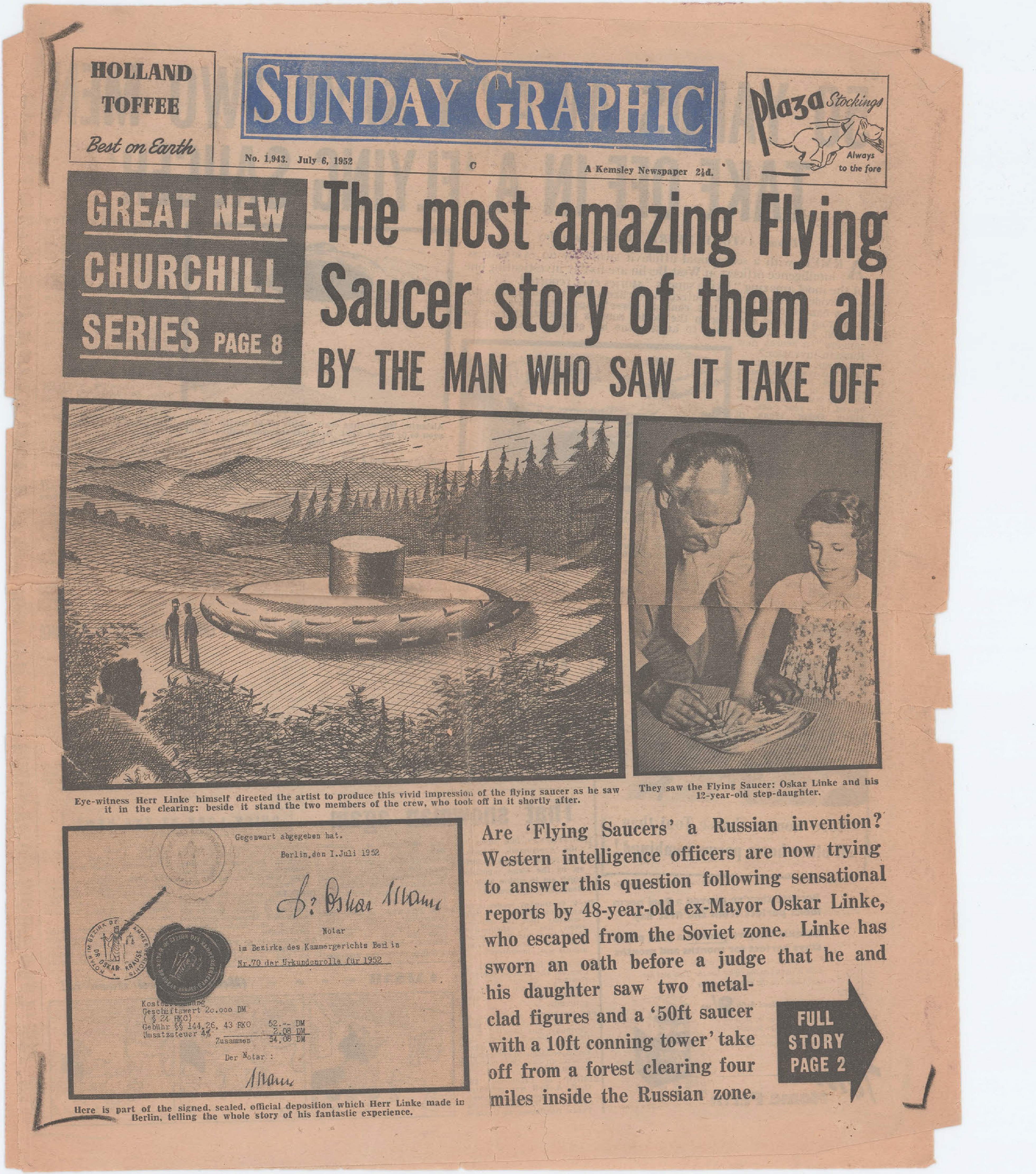
Artist's impression of flying saucer in forest clearing with two figures
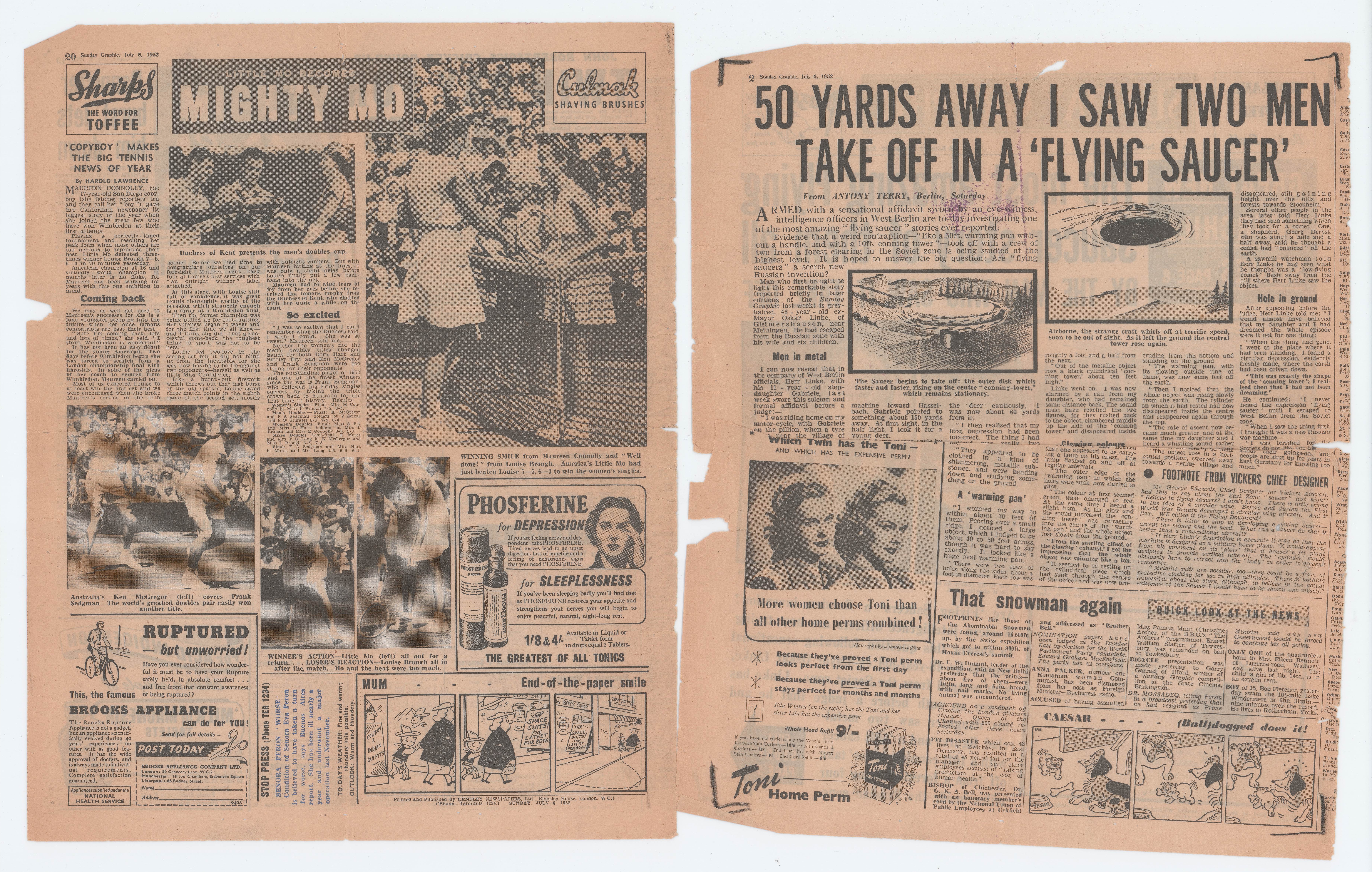
Left page: newspaper page showing 'MIGHTY MO' sports coverage with multiple photographs and advertisements
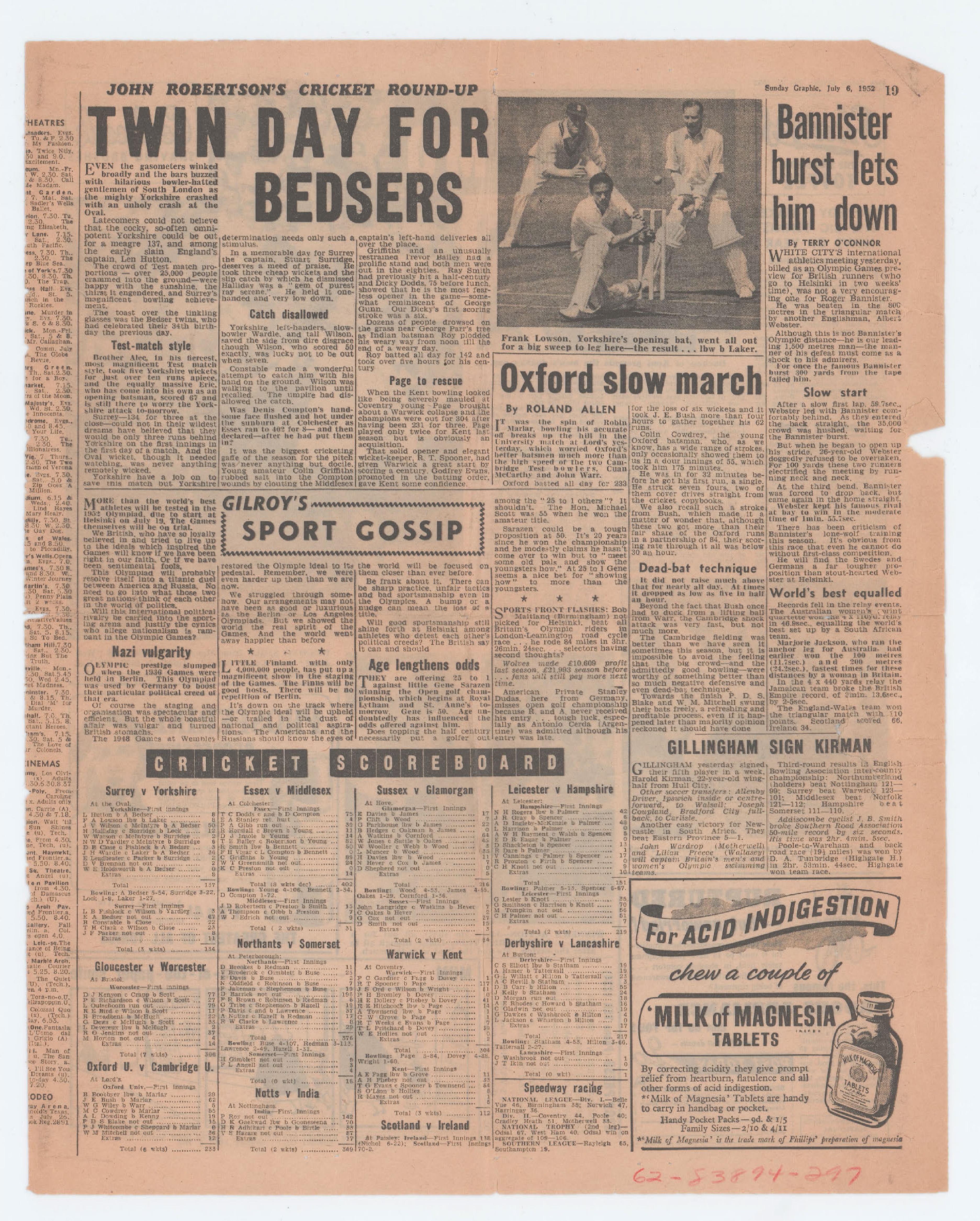
Cricket players, one batting, two standing behind

3 cent United States postage stamp
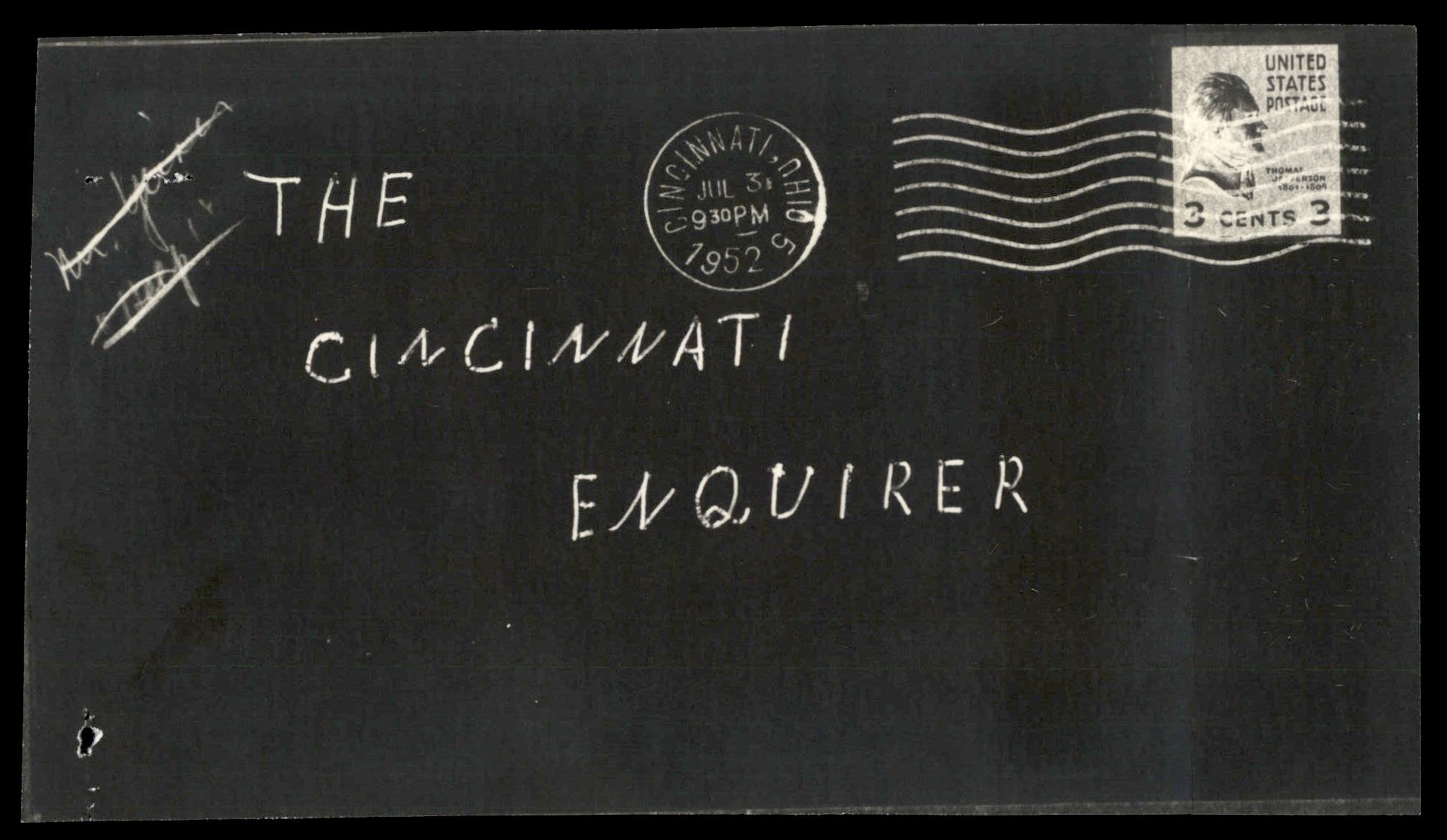
Photograph of envelope addressed to The Cincinnati Enquirer with postmark and 3-cent stamp
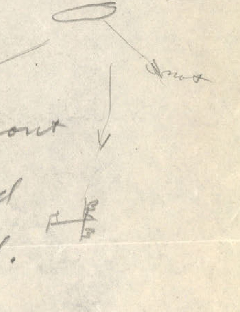
Simple sketch showing angles and directional arrows
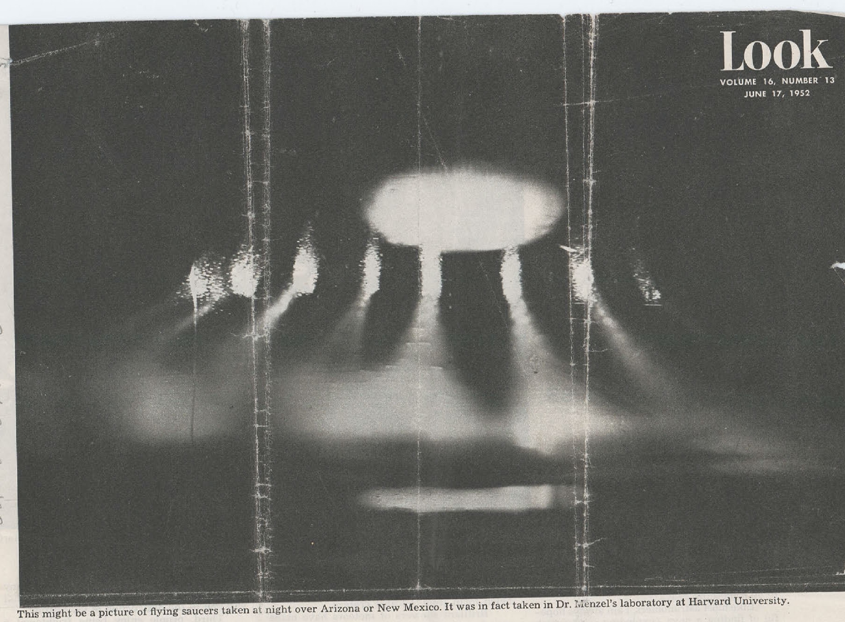
This might be a picture of flying saucers taken at night over Arizona or New Mexico. It was in fact taken in Dr. Menzel's laboratory at Harvard University.
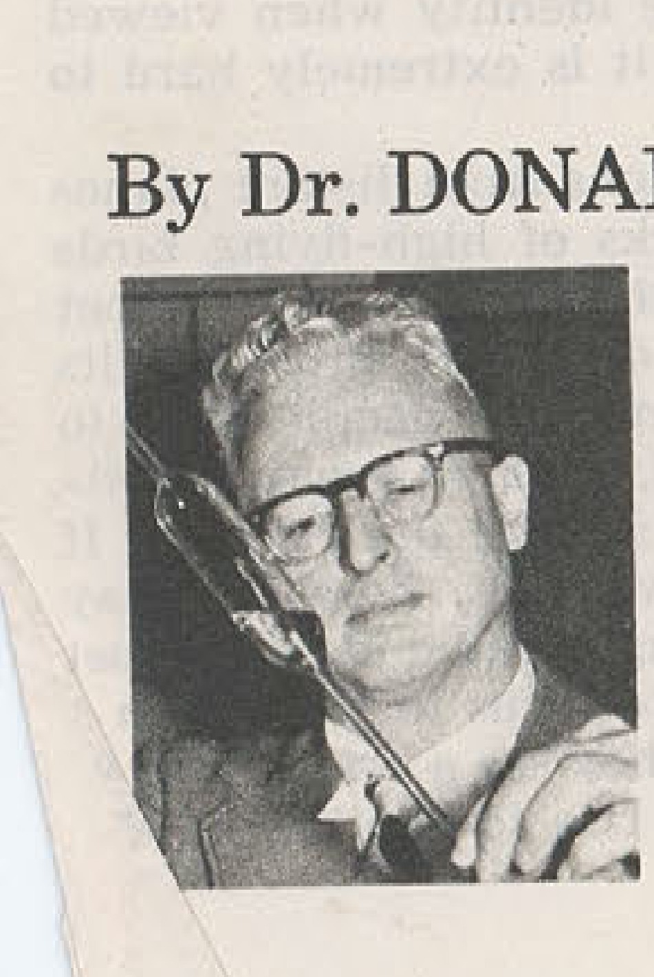
Portrait photograph of Dr. Donald H. Menzel
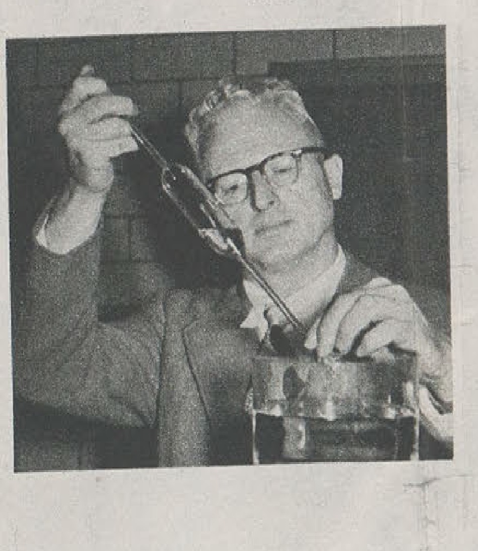
Man holding what appears to be a model or device
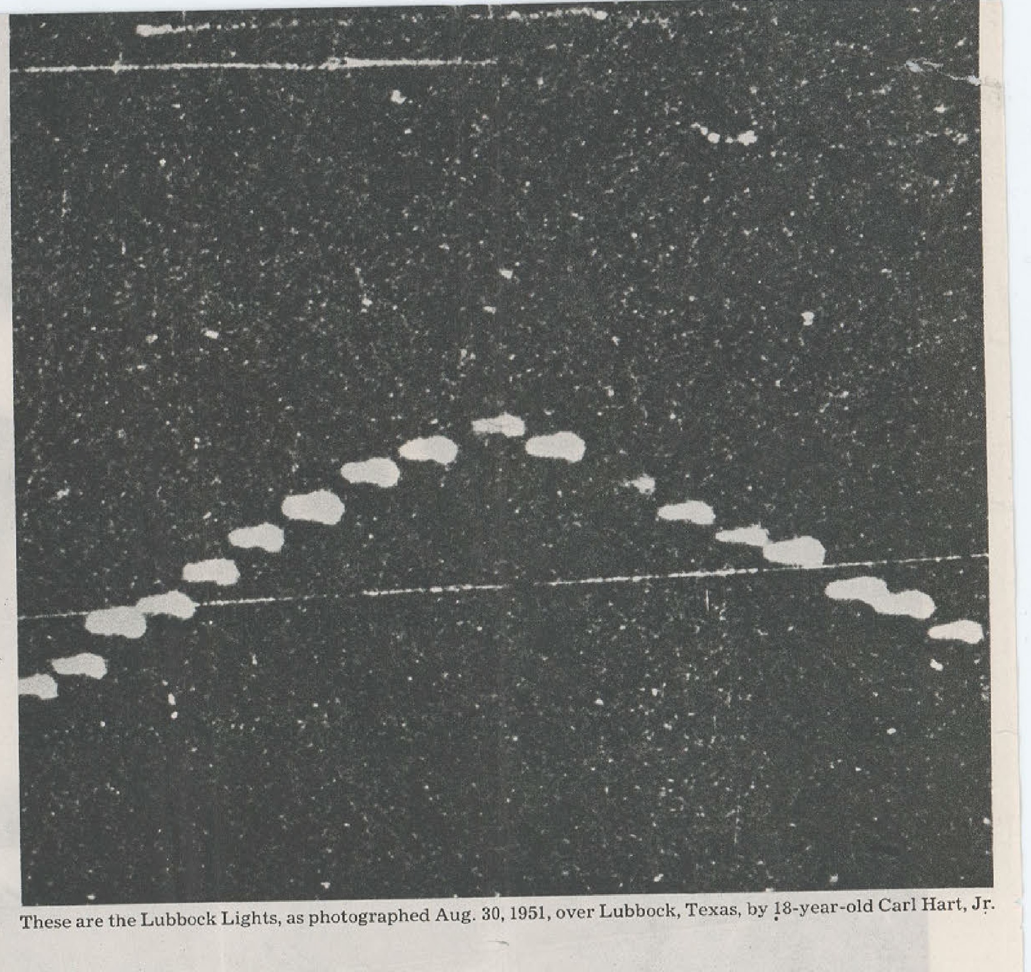
These are the Lubbock Lights, as photographed Aug. 30, 1951, over Lubbock, Texas, by 18-year-old Carl Hart, Jr.
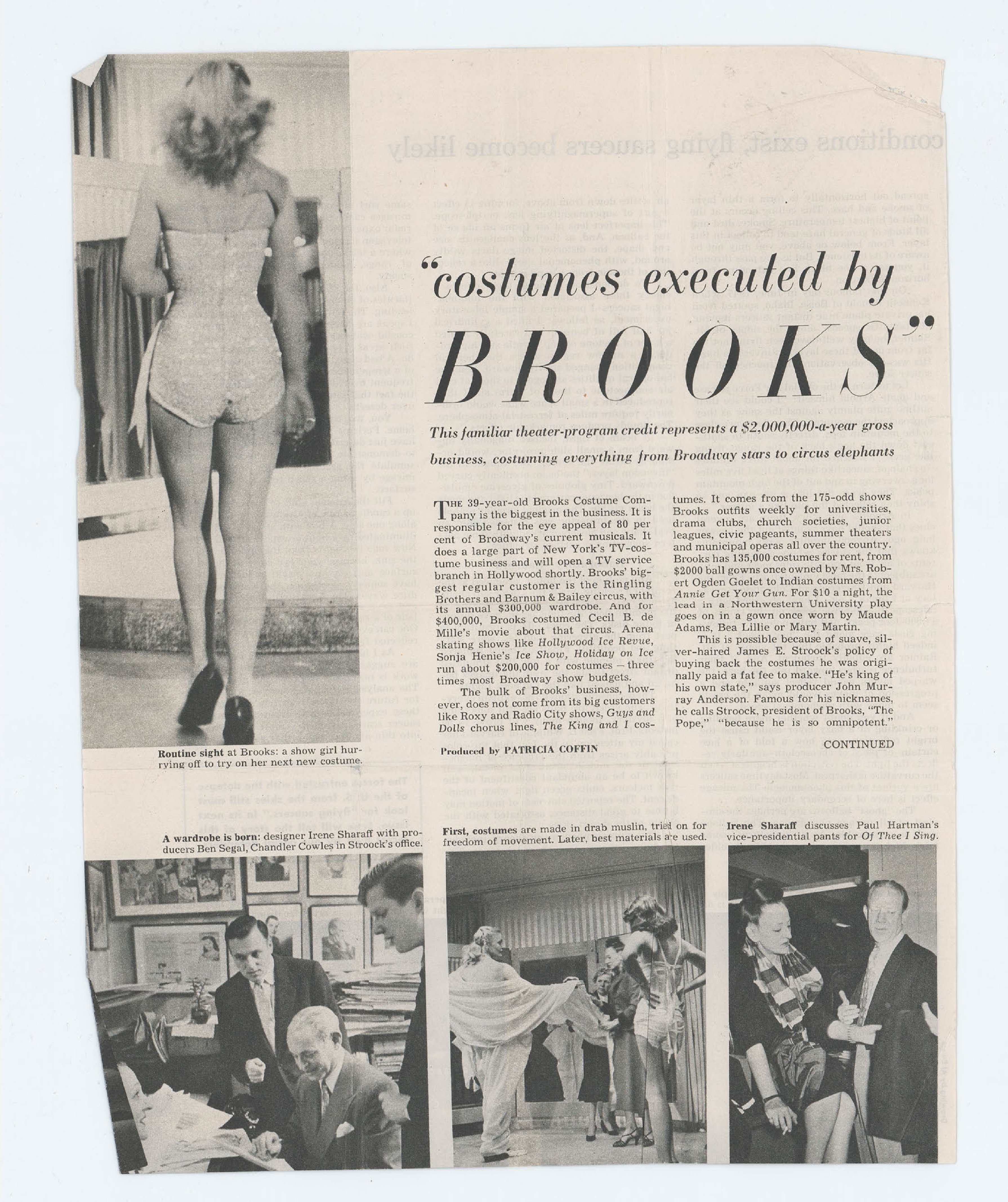
Routine sight at Brooks: a show girl hurrying off to try on her next new costume.
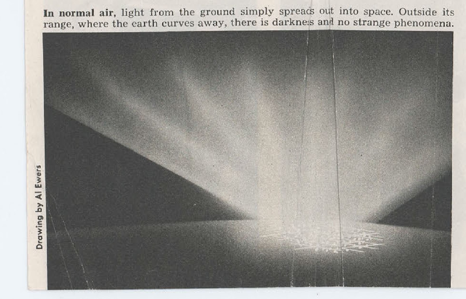
In normal air, light from the ground simply spreads out into space. Outside its range, where the earth curves away, there is darkness and no strange phenomena.
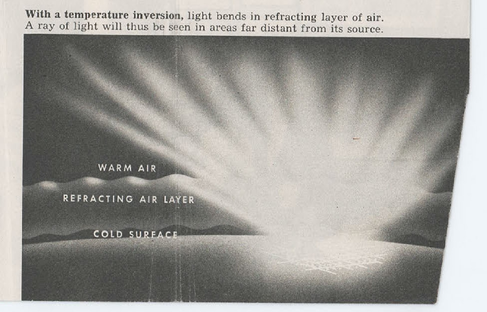
With a temperature inversion, light bends in refracting layer of air. A ray of light will thus be seen in areas far distant from its source. Labels show WARM AIR, REFRACTING AIR LAYER, COLD SURFACE.
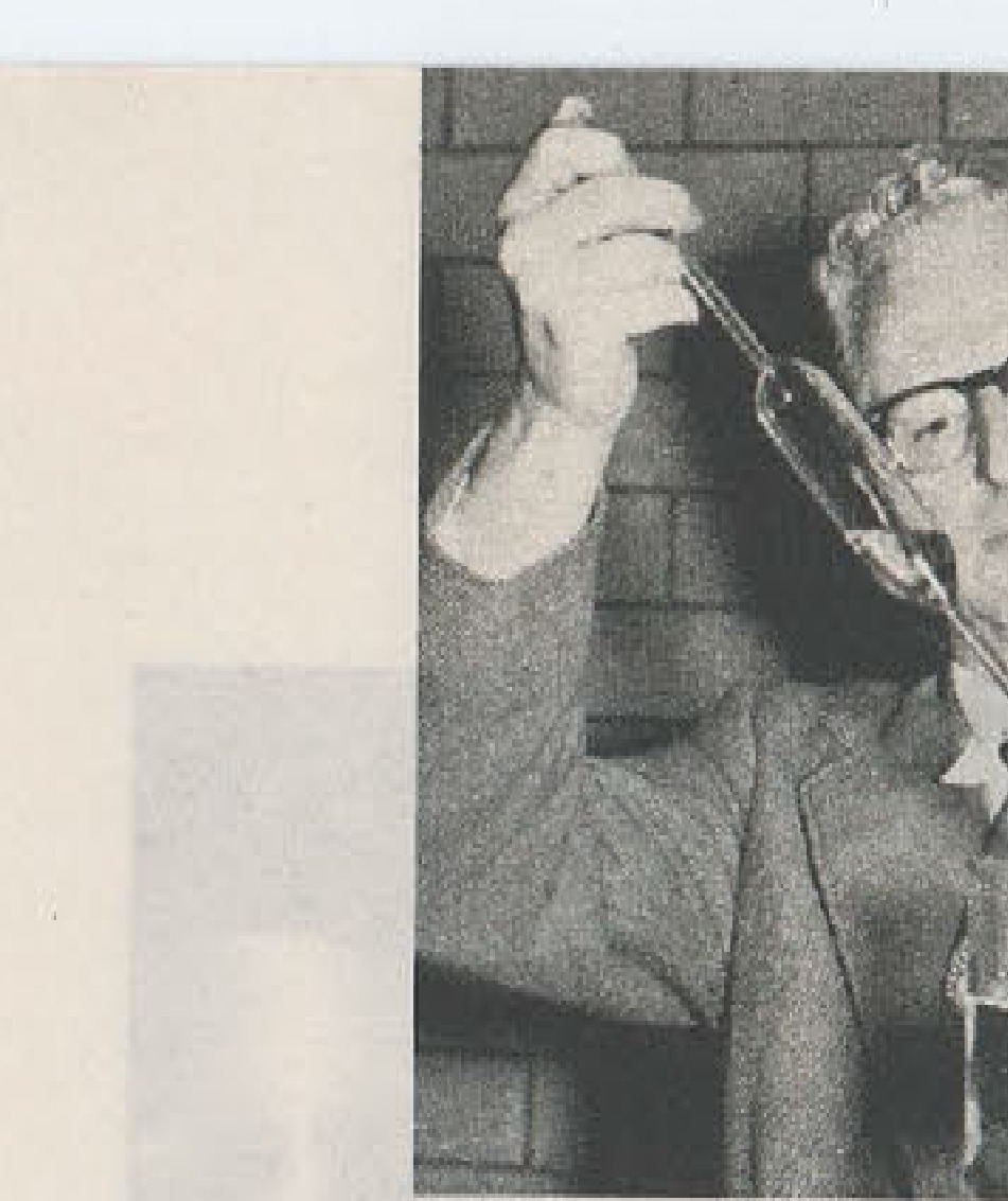
Man in glasses holding telescope or similar instrument
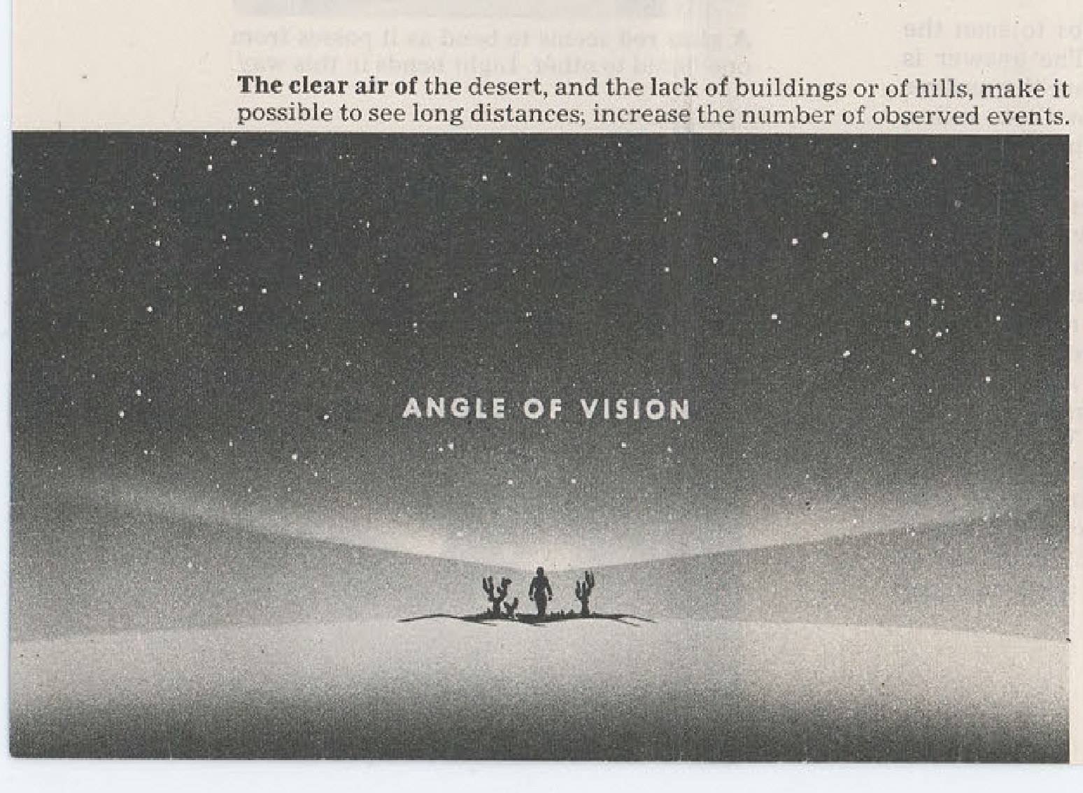
ANGLE OF VISION - Desert scene showing light rays and silhouettes
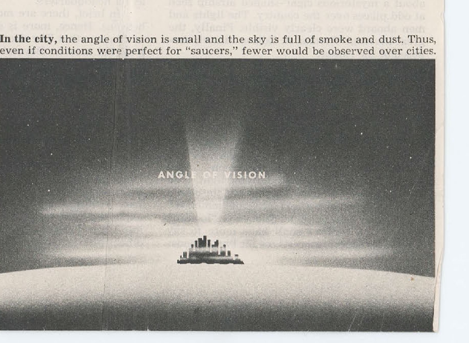
ANGLE OF VISION - City skyline showing light rays
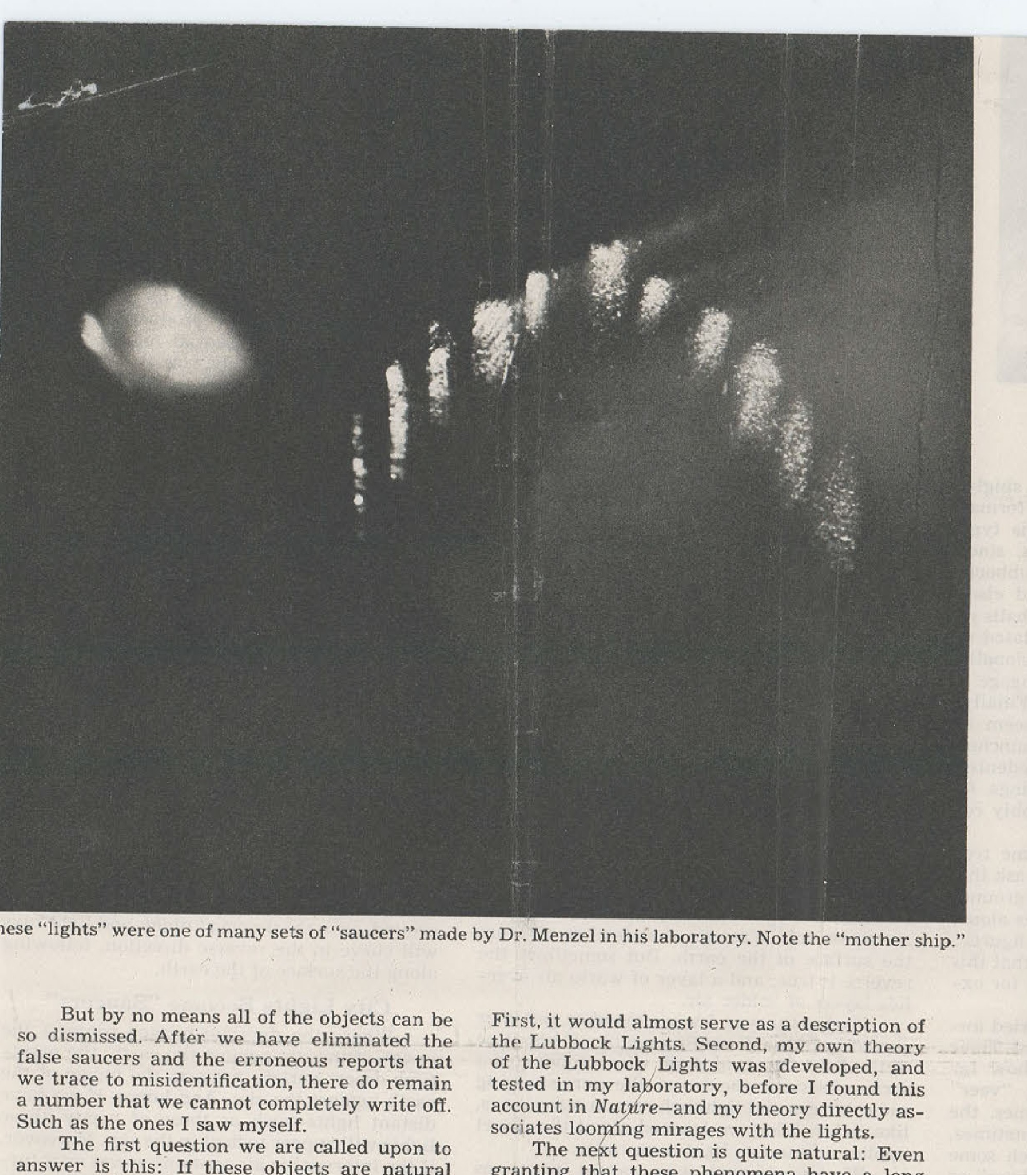
These "lights" were one of many sets of "saucers" made by Dr. Menzel in his laboratory. Note the "mother ship."
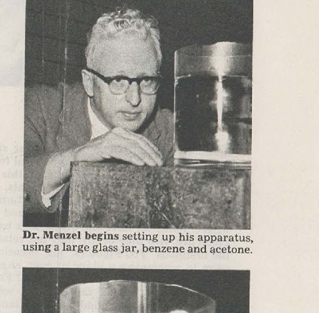
Photographed by Arthur Rothstein - Dr. Menzel begins setting up his apparatus, using a large glass jar, benzene and acetone.
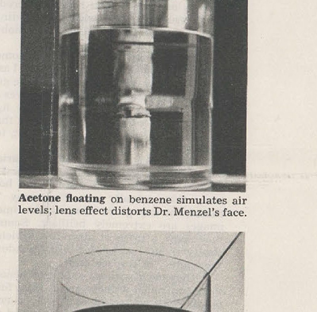
Acetone floating on benzene simulates air levels; lens effect distorts Dr. Menzel's face.
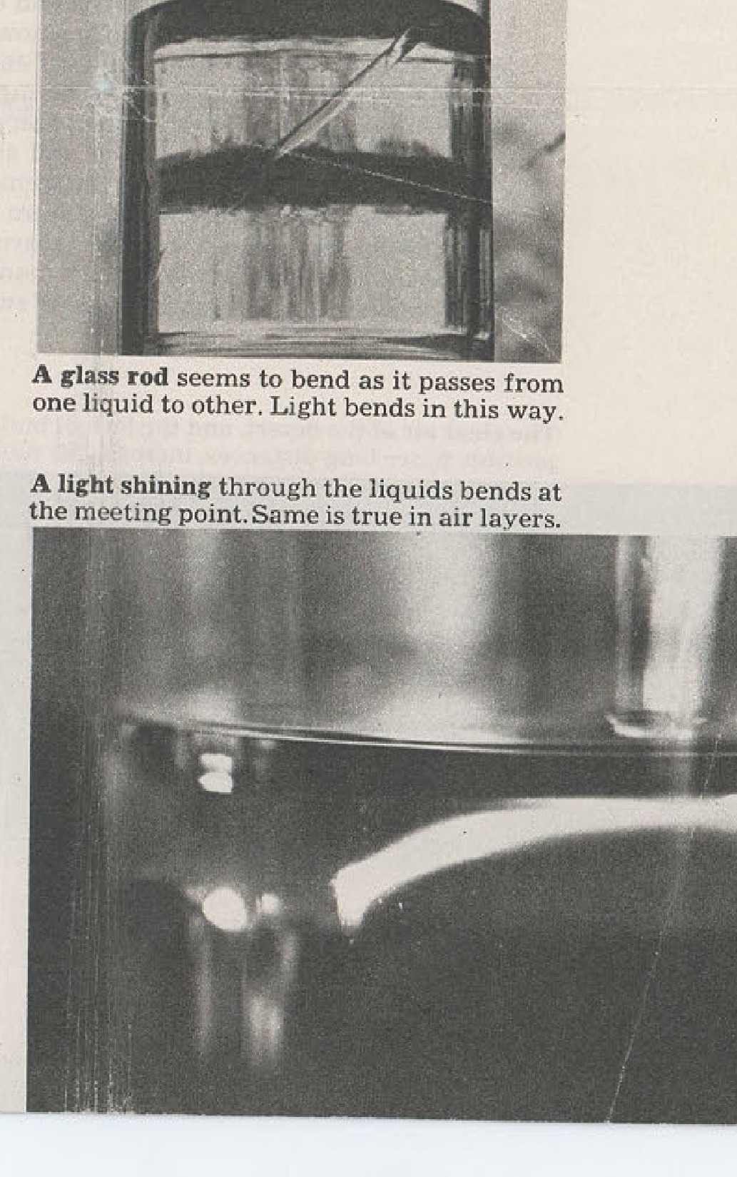
A glass rod seems to bend as it passes from one liquid to other. Light bends in this way. A light shining through the liquids bends at the meeting point. Same is true in air layers.

A political cartoon depicts a man resembling Stalin playing a violin over a crying baby in a cradle labeled 'WORLD UNREST'.
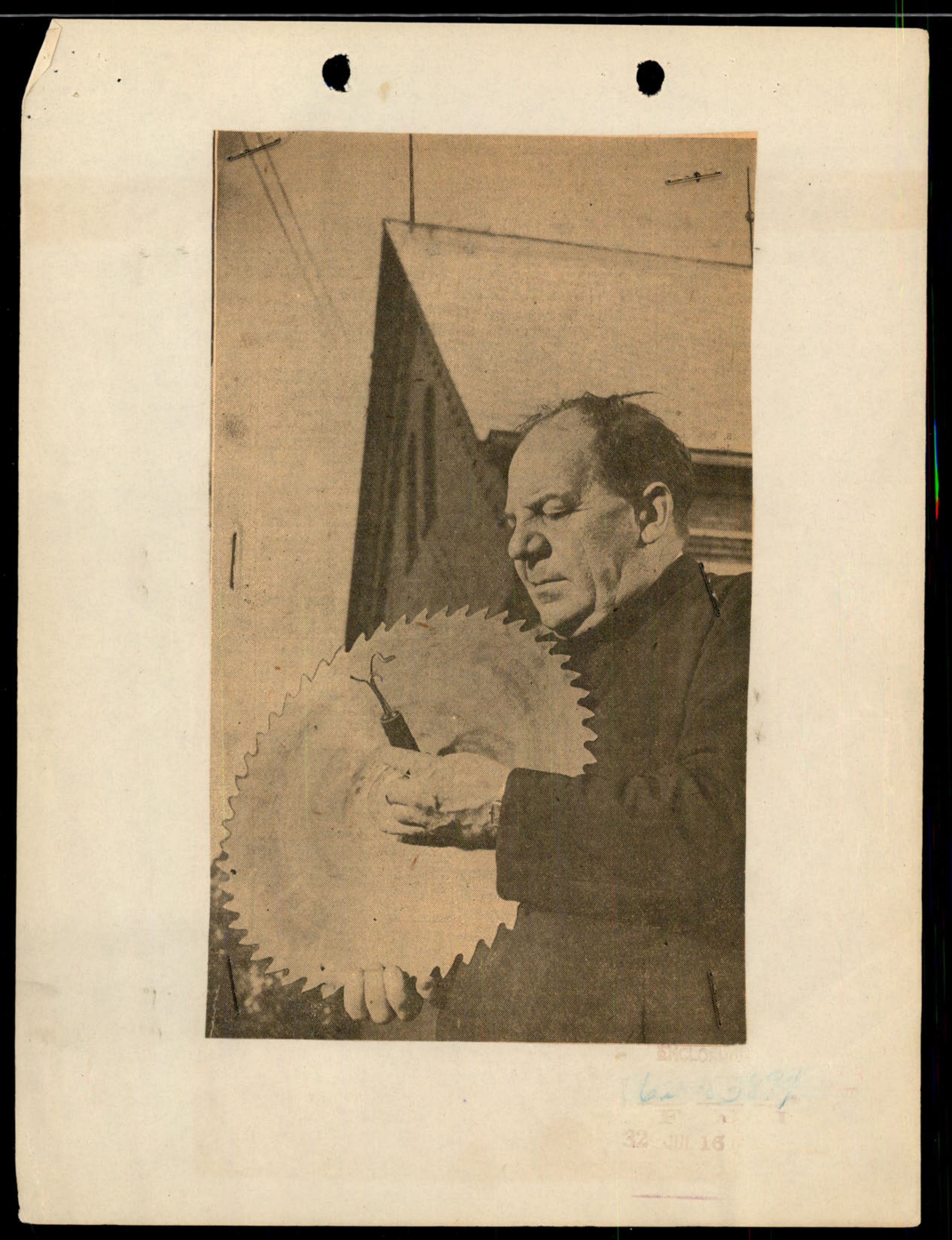
A man, identified in other clippings as Father Joseph Brasky, holds a large circular saw blade.
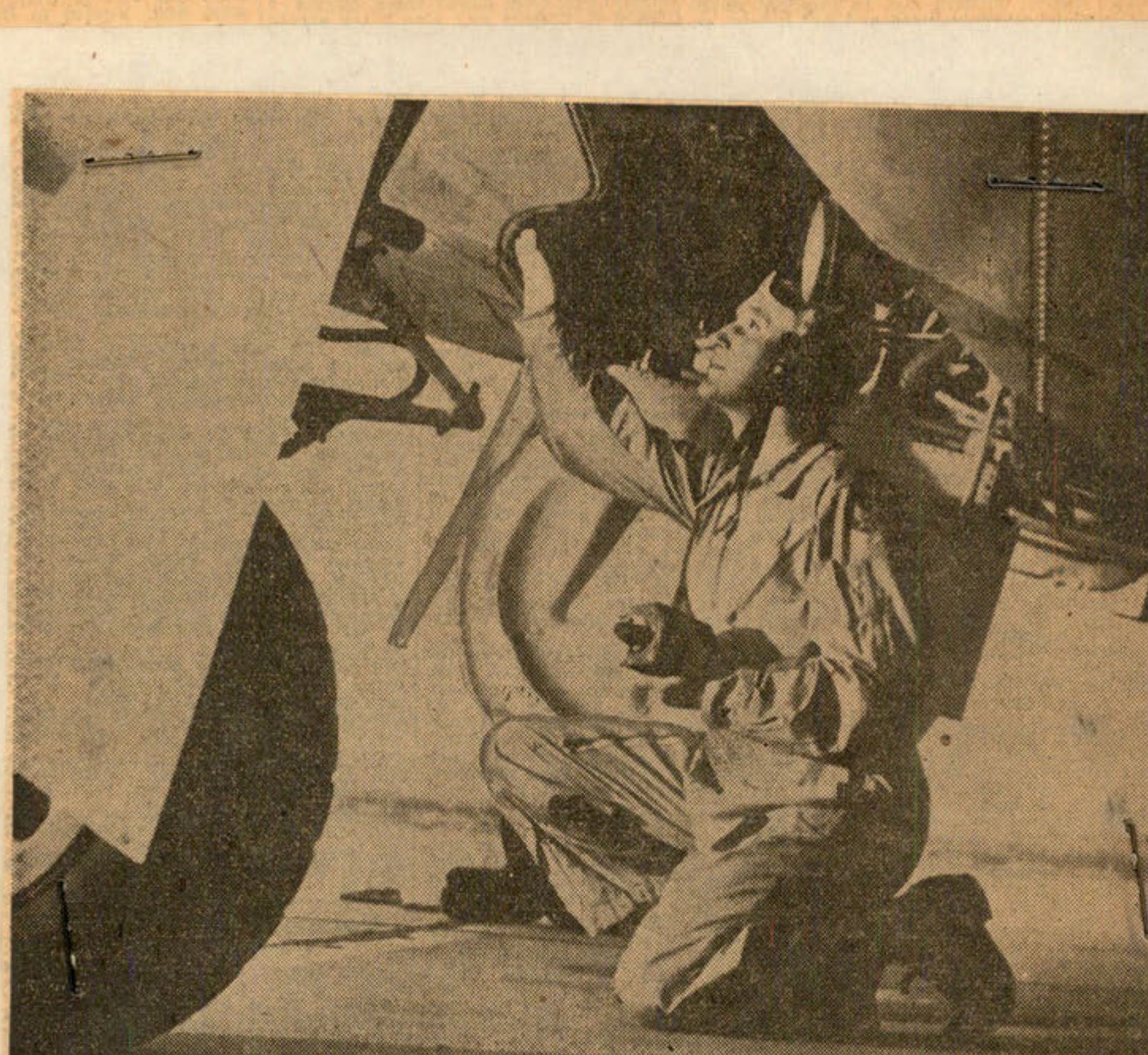
A man in a military uniform kneels under the wing of an airplane.
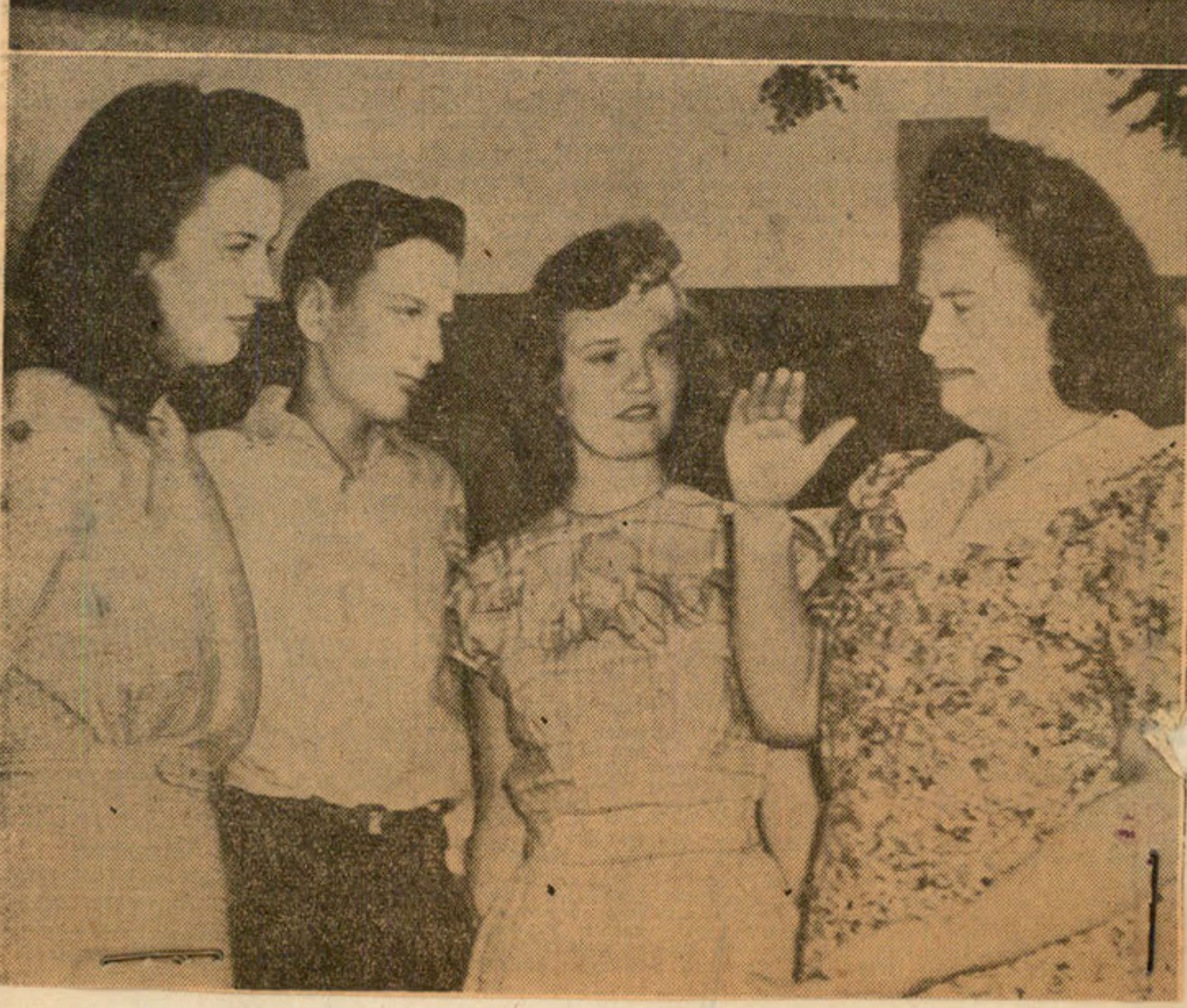
A group of four people (one man, three women) appear to be in conversation.
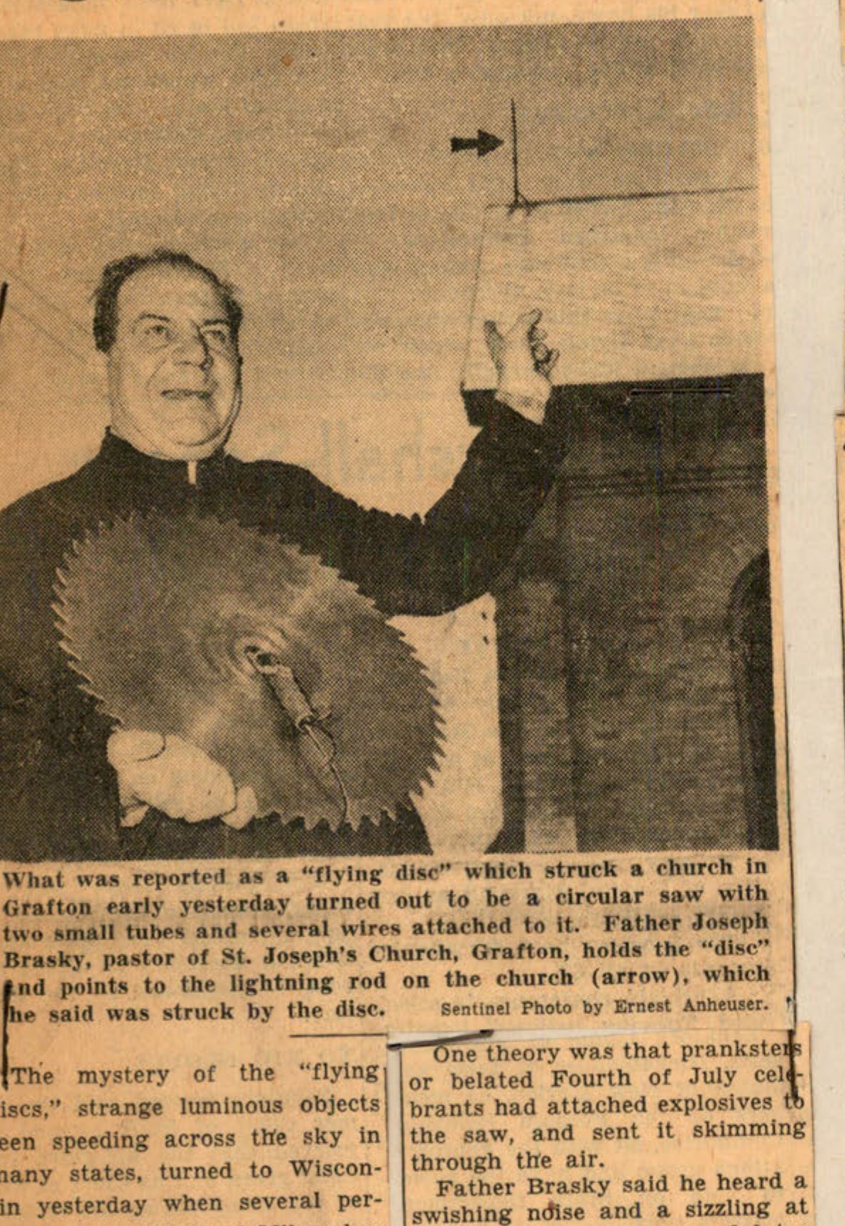
What was reported as a "flying disc" which struck a church in Grafton early yesterday turned out to be a circular saw with two small tubes and several wires attached to it. Father Joseph Brasky, pastor of St. Joseph's Church, Grafton, holds the "disc" and points to the lightning rod on the church (arrow), which he said was struck by the disc. -Sentinel Photo by Ernest Anheuser.
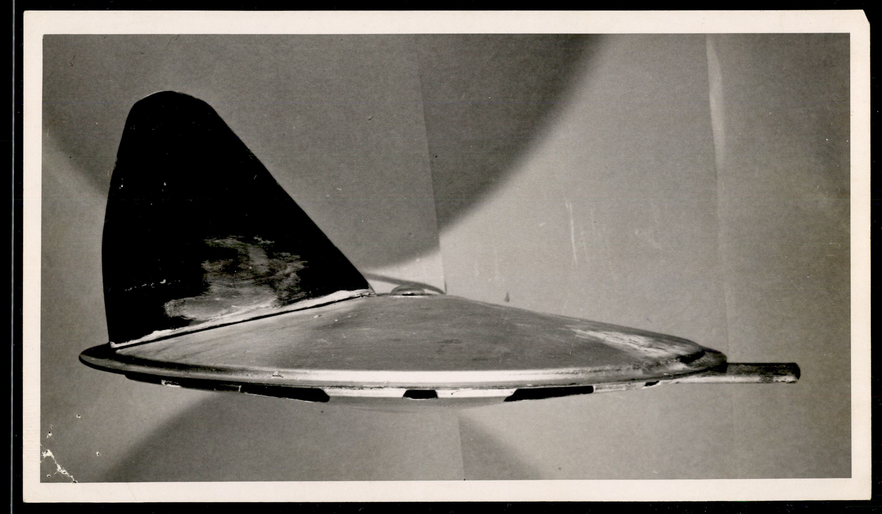
Side view of a metallic, disc-shaped object with a large vertical fin attached to the top.
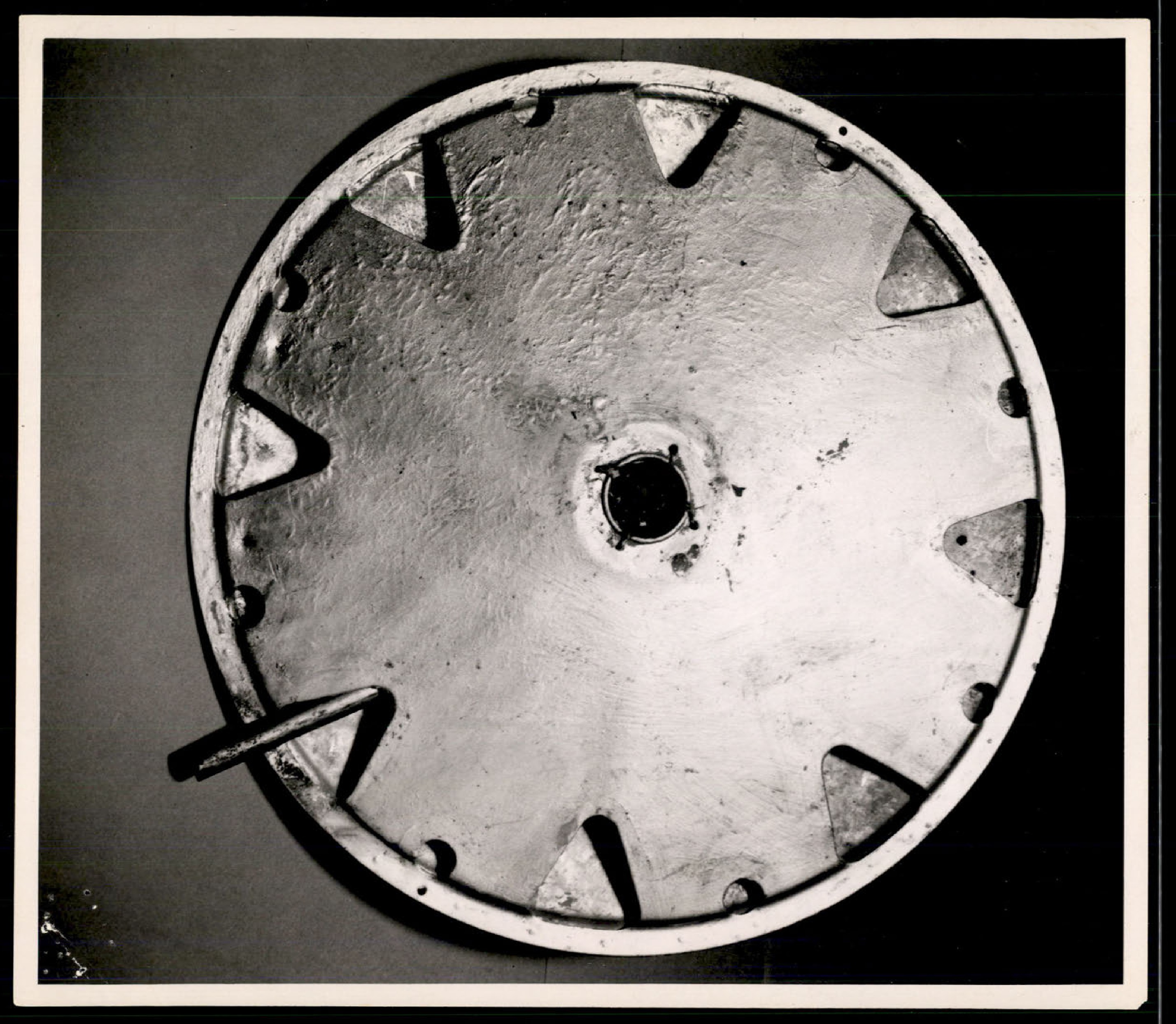
Top or bottom view of a metallic, circular object with triangular cutouts around the perimeter and a central hole.
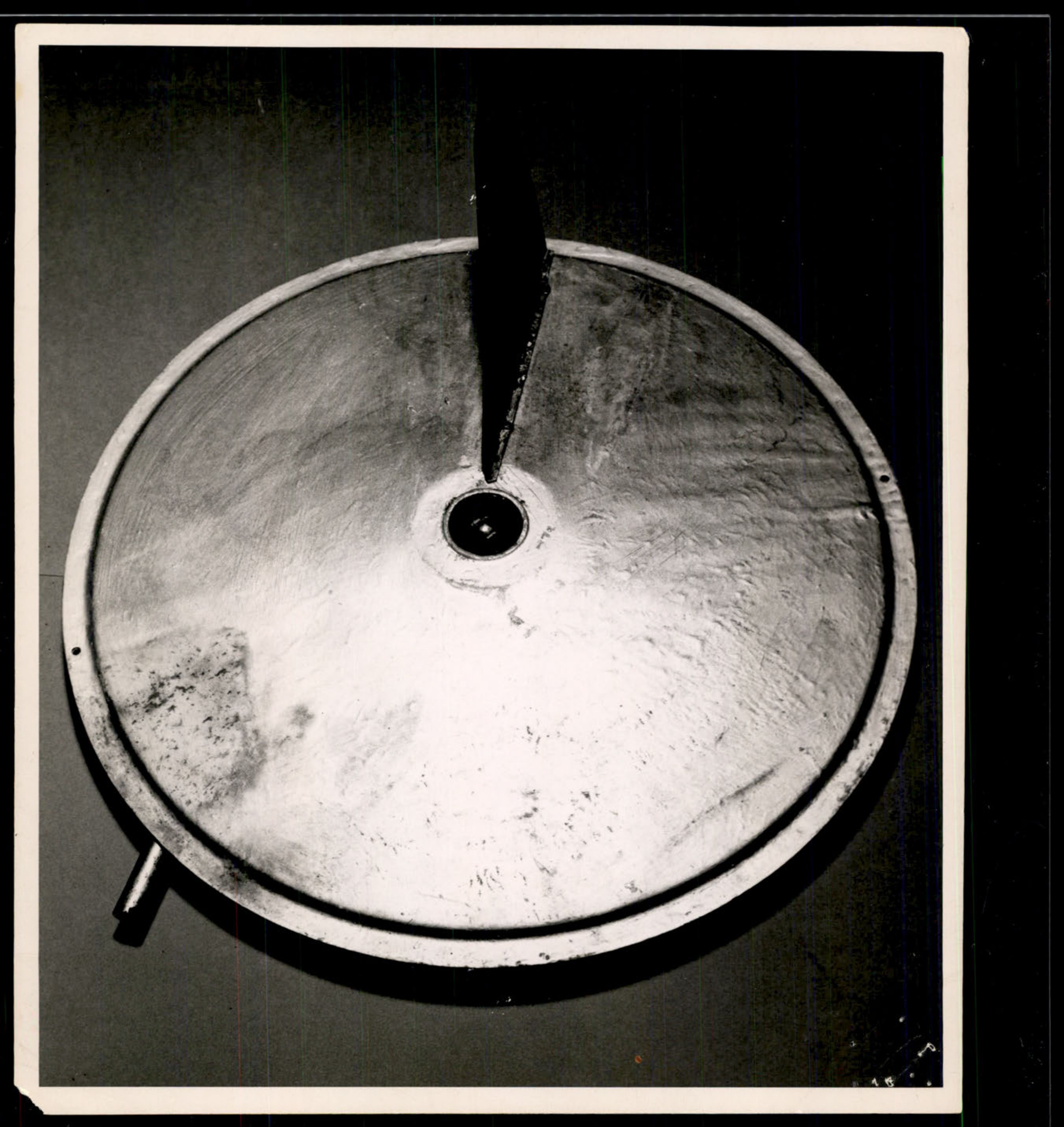
Photograph showing the bottom view of a circular, metallic object, likely the 'flying disc' recovered in North Hollywood, California.
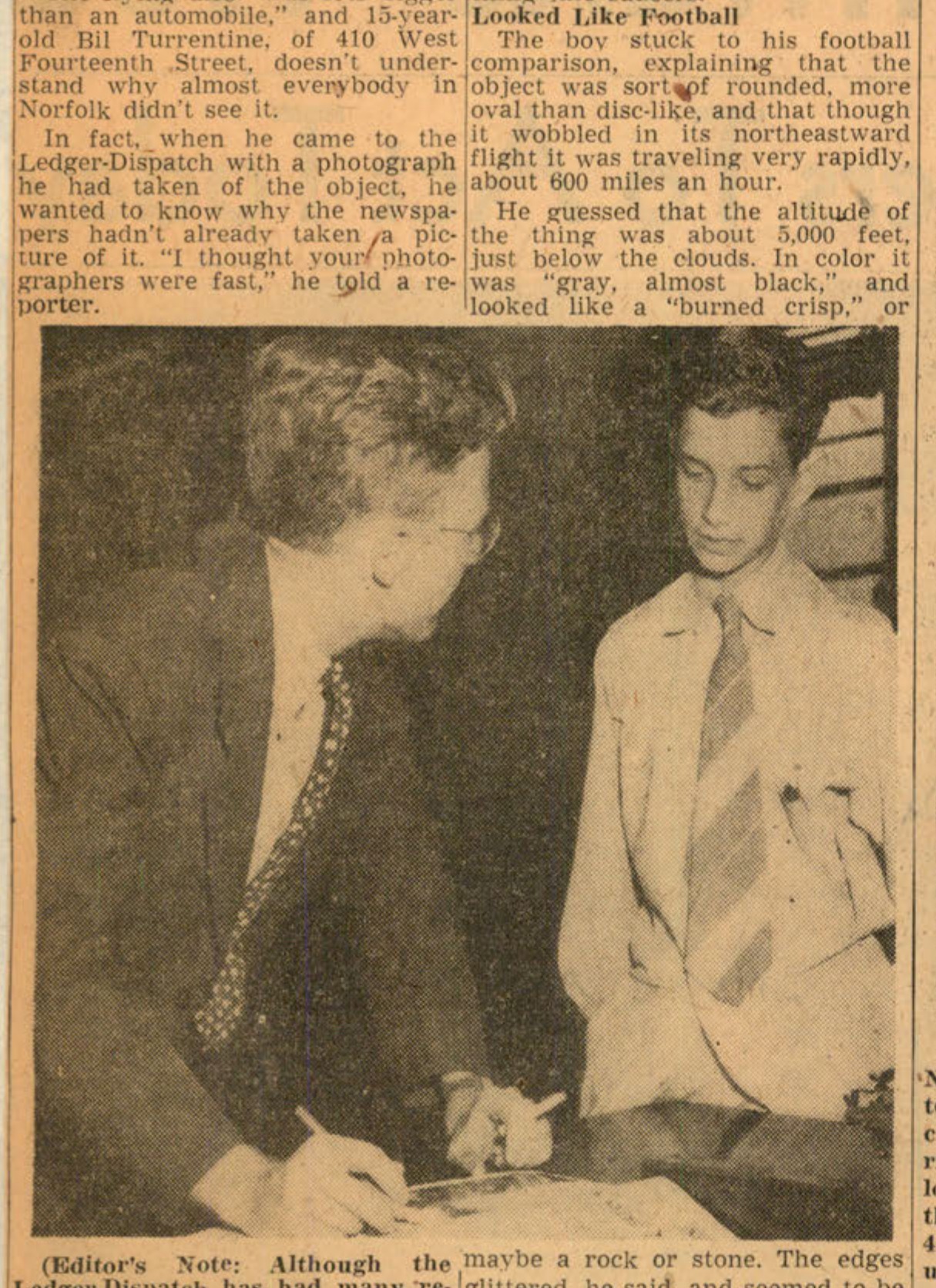
Bill Turrentine (right) with Ledger-Dispatch reporter George Herbert (left).
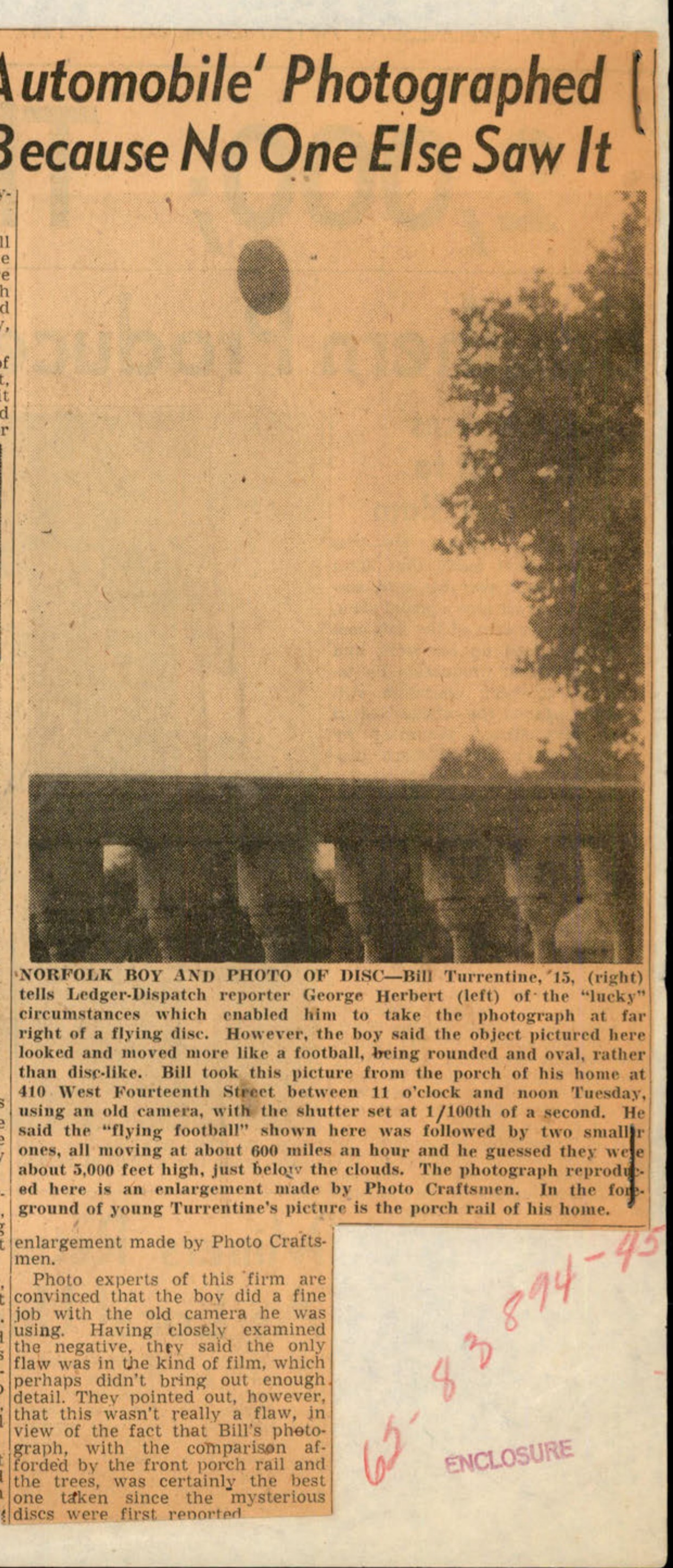
Photograph of a flying disc taken by Bill Turrentine.
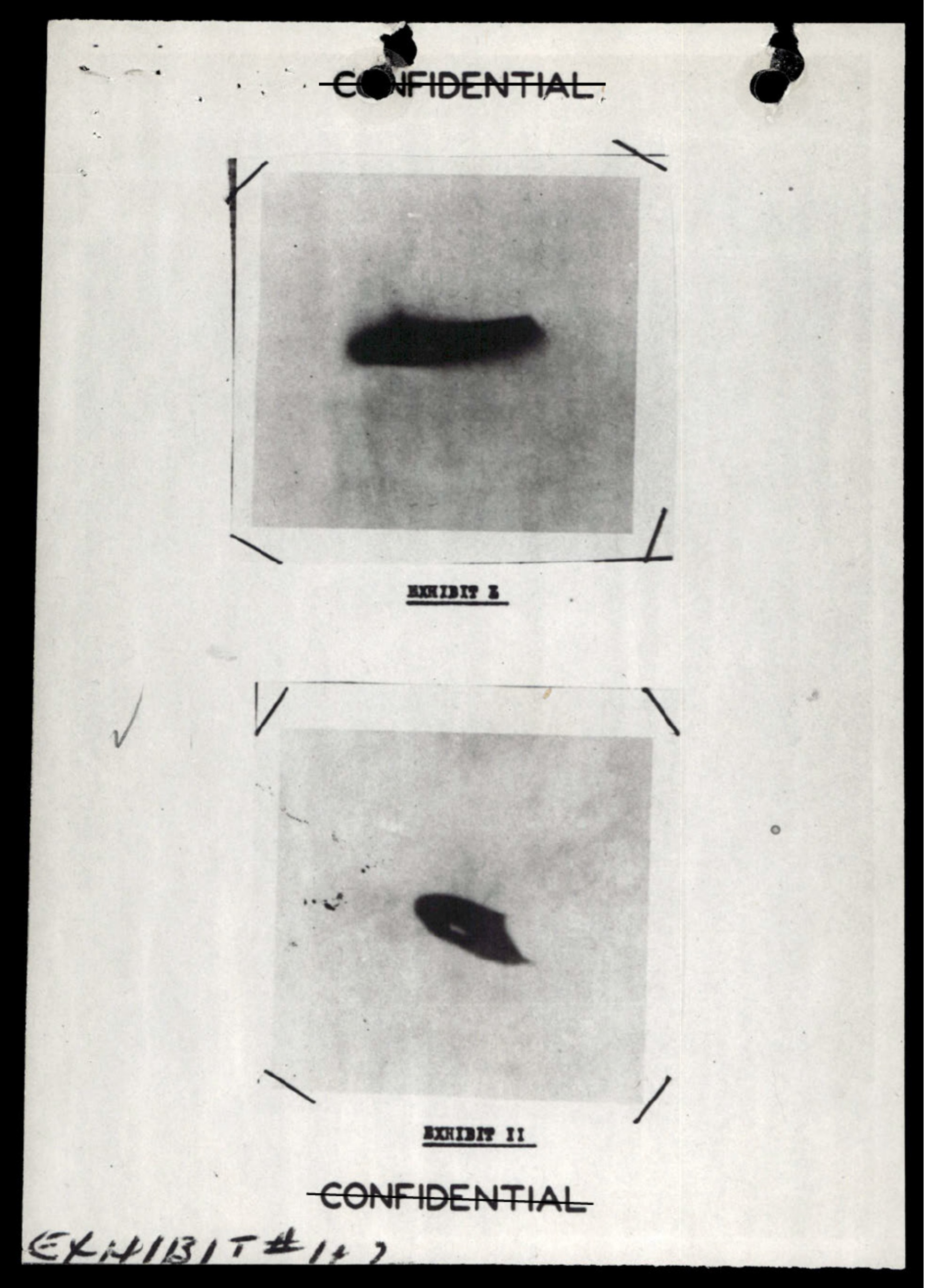
EXHIBIT I: A dark, elongated, slightly curved object against a light background.
NASA 'worm' logo

NASA 'worm' logo

NASA 'worm' logo
A grainy, black-and-white sensor image showing a central crosshair reticle with a small object near the center, a timestamp, and several redacted data blocks.

A small red circle, possibly highlighting an object on the original unredacted image.
Enhanced, blurry image of an object, possibly L-shaped or with protrusions.
Second enhanced, blurry image of an object, appearing somewhat symmetrical with a central column.
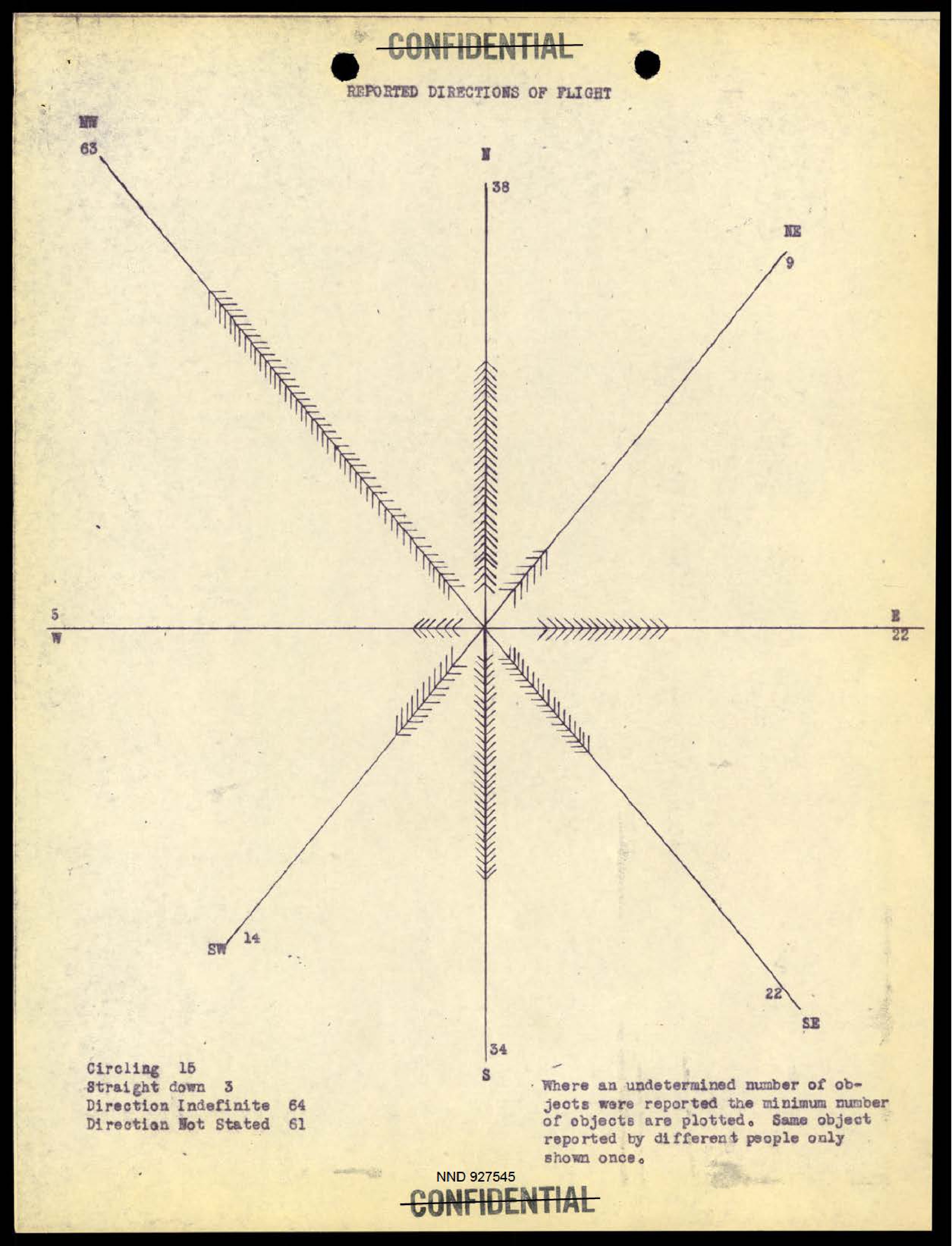
A compass rose diagram showing the reported directions of flight for UFO sightings, with counts for each direction and a summary of non-directional reports.
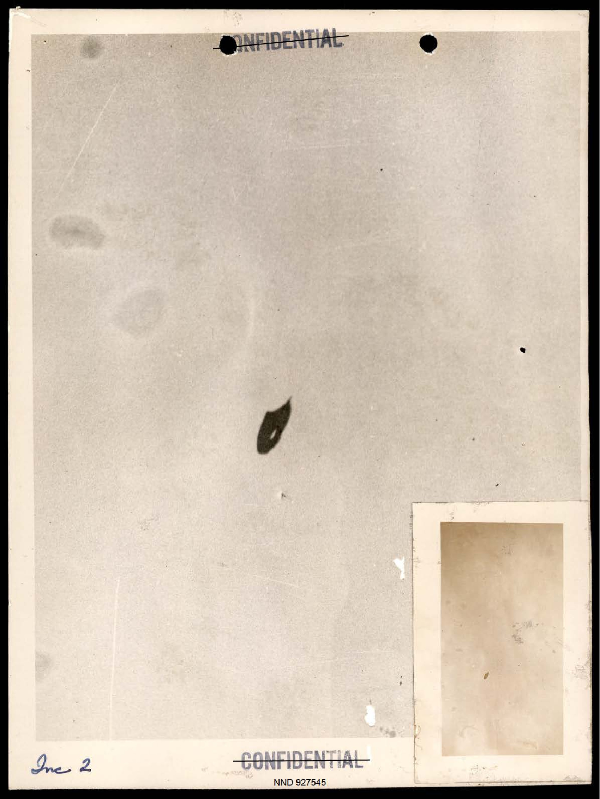
Photograph of a dark, teardrop-shaped object against a light background.
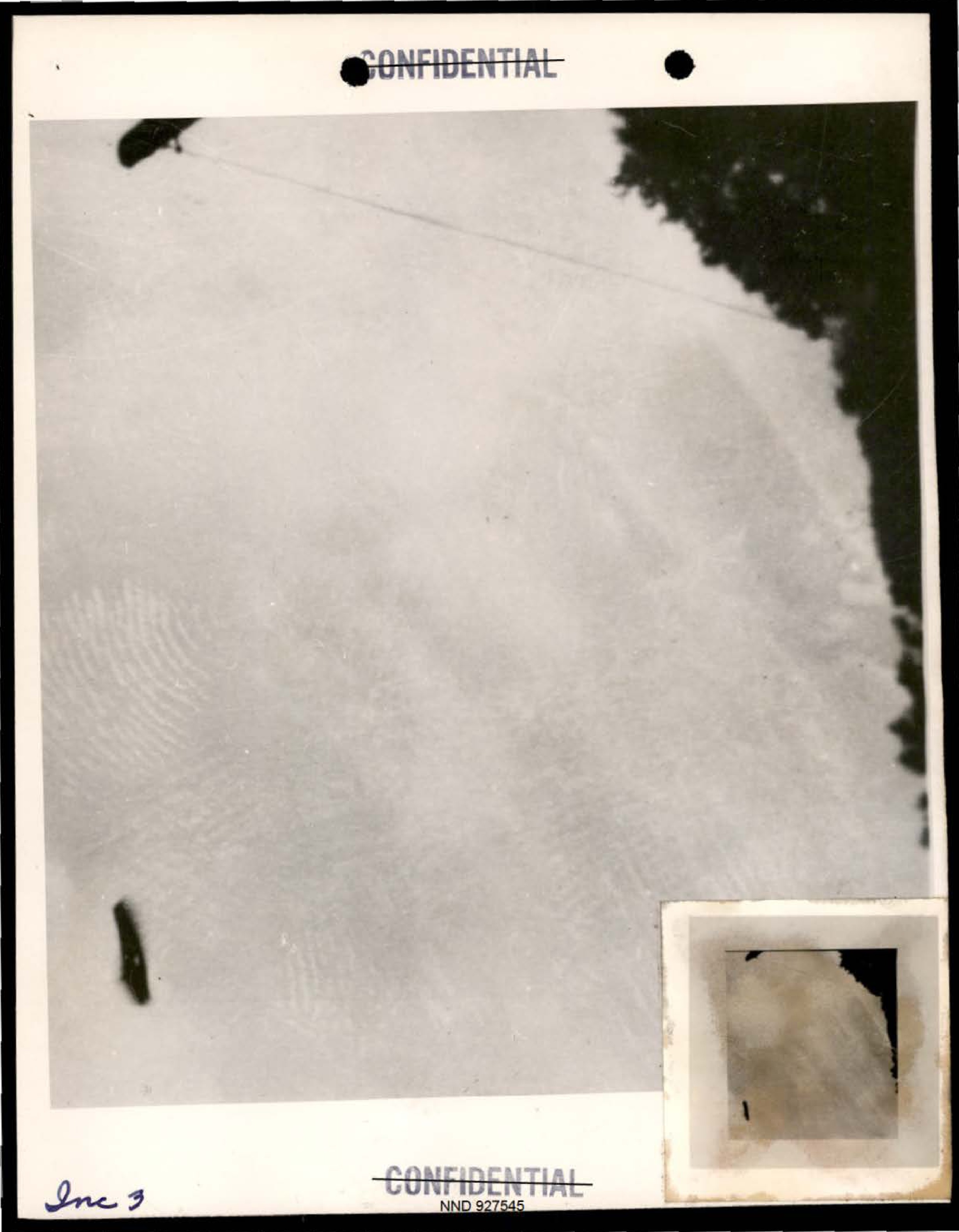
Photograph showing several dark objects and a fingerprint-like pattern.
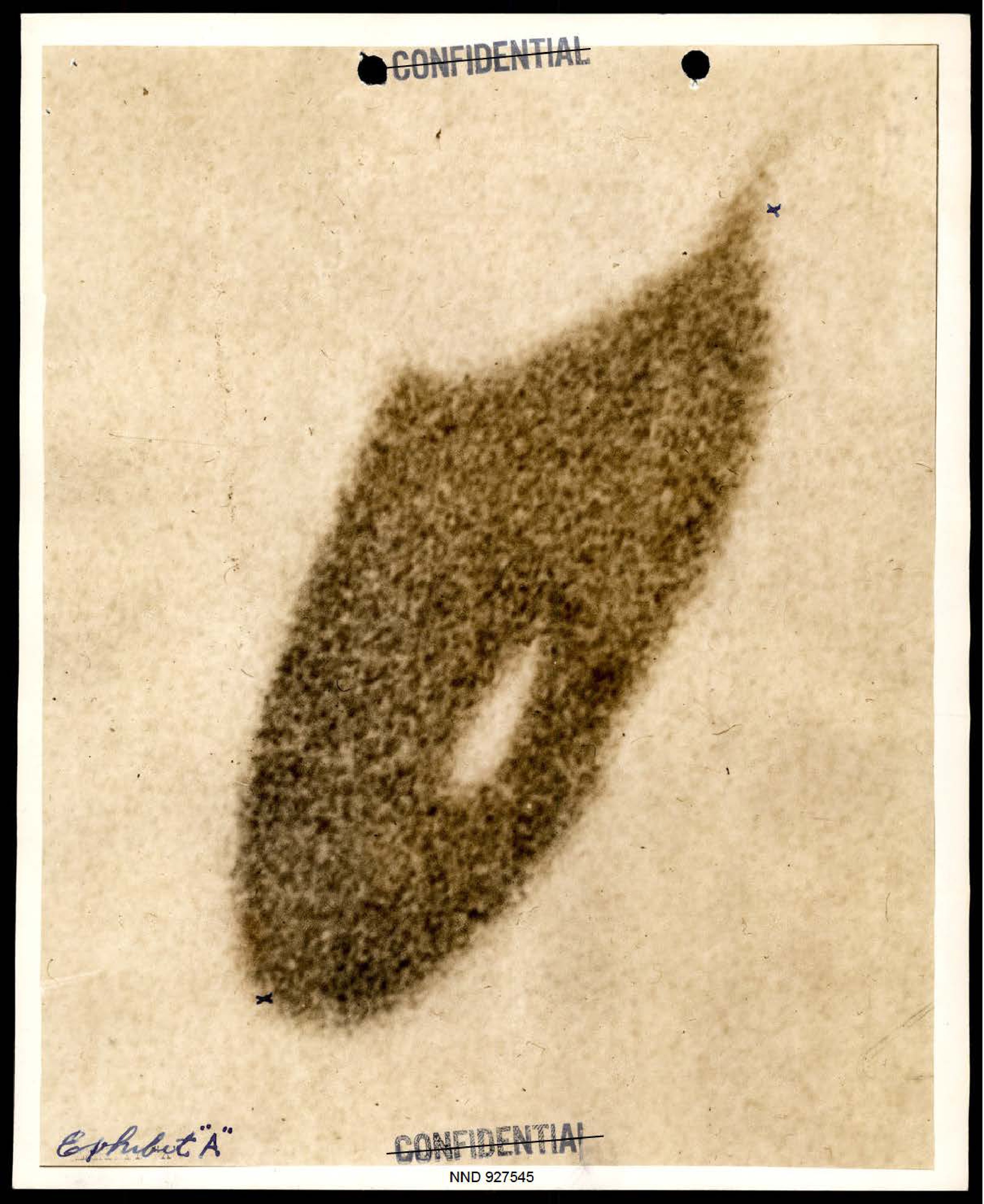
Enlarged photograph of a dark, teardrop-shaped object, labeled Exhibit 'A'.
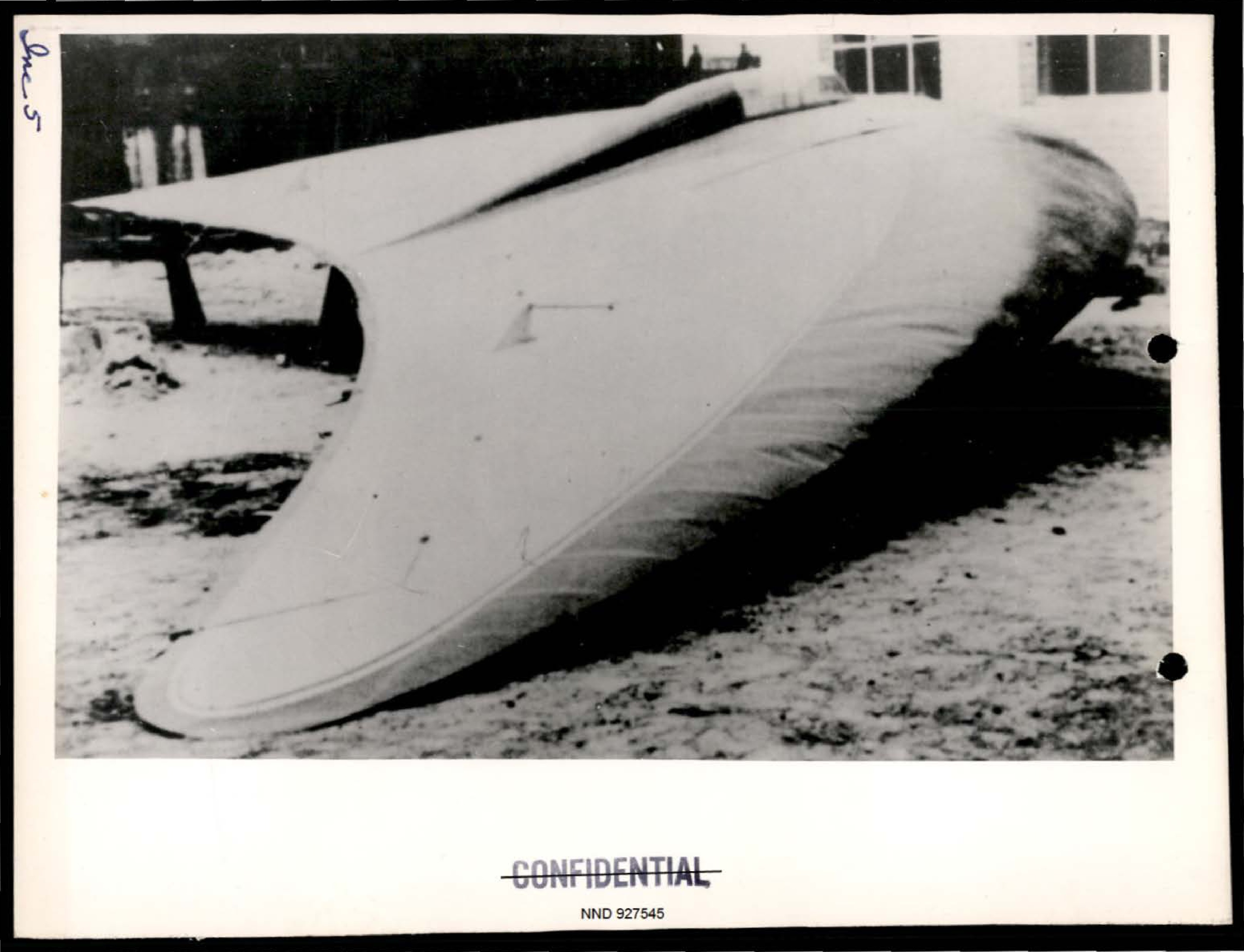
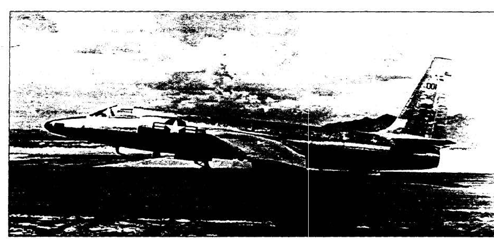
Photograph of a delta-wing or flying-wing aircraft on the ground.
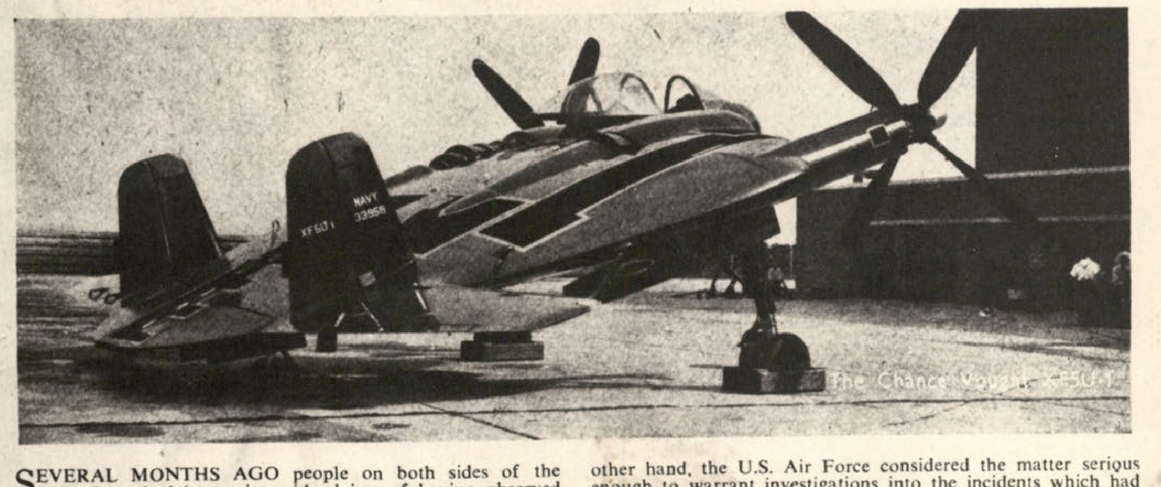
Chance Vought XF5U-1
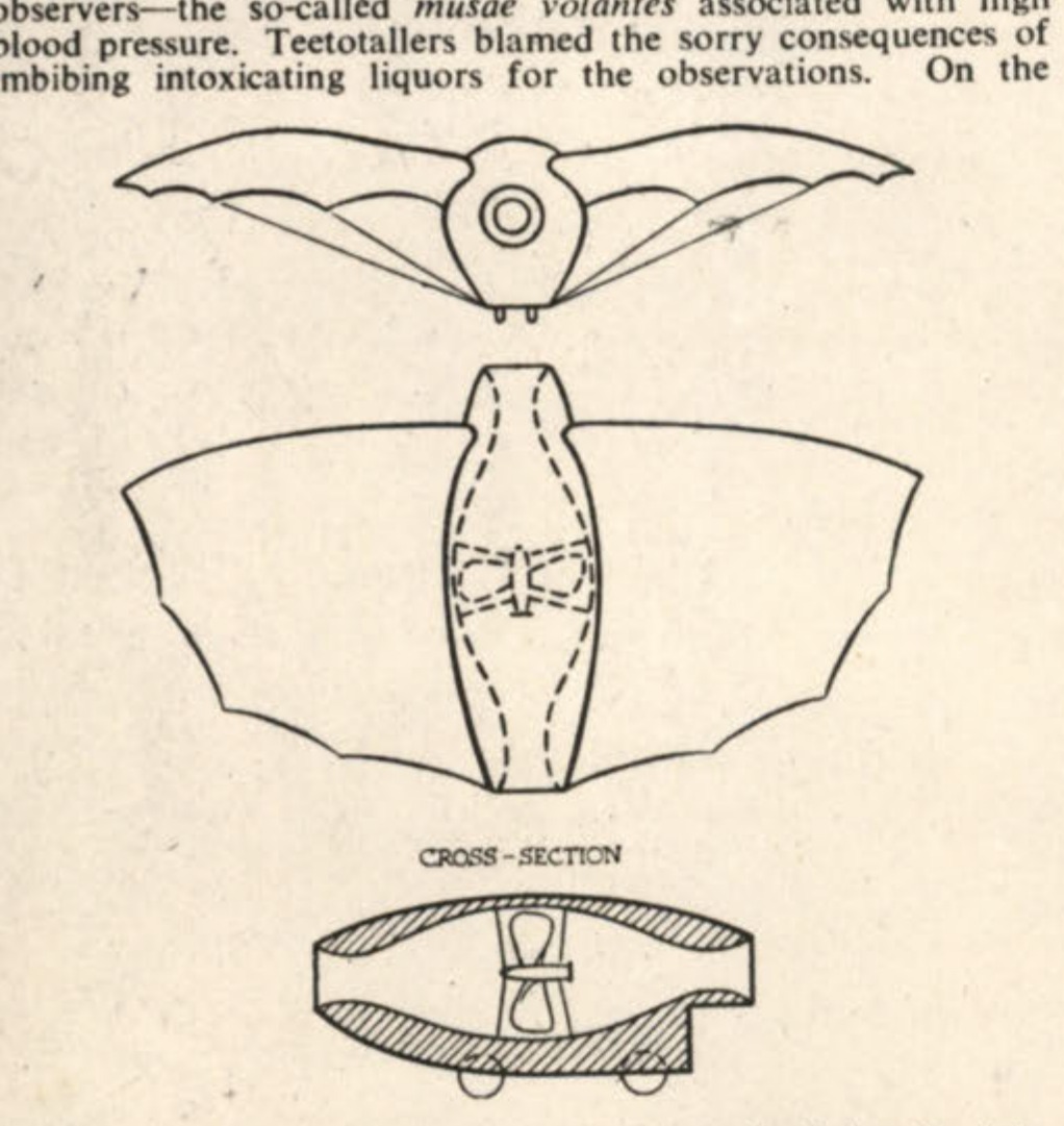
CROSS-SECTION
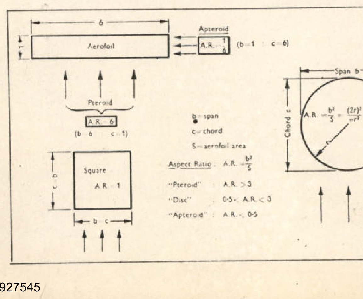
Diagram showing different aerofoil shapes and aspect ratios (A.R.).
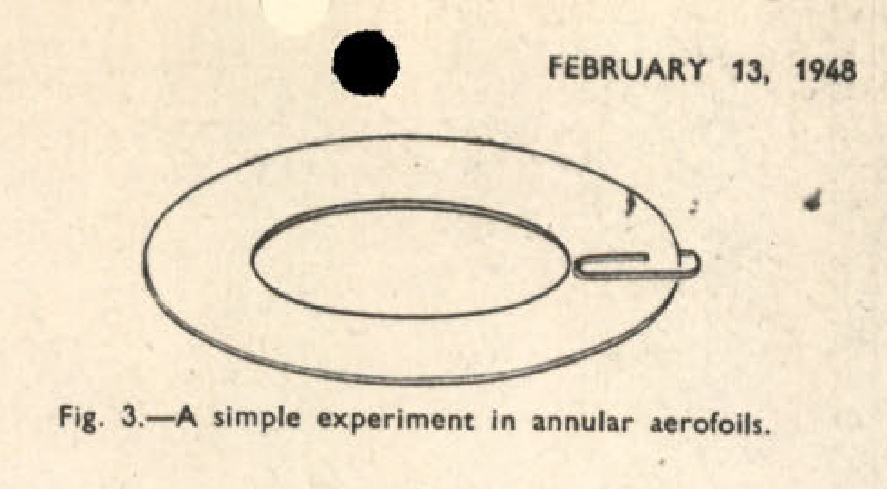
Fig. 3. A simple experiment in annular aerofoils.
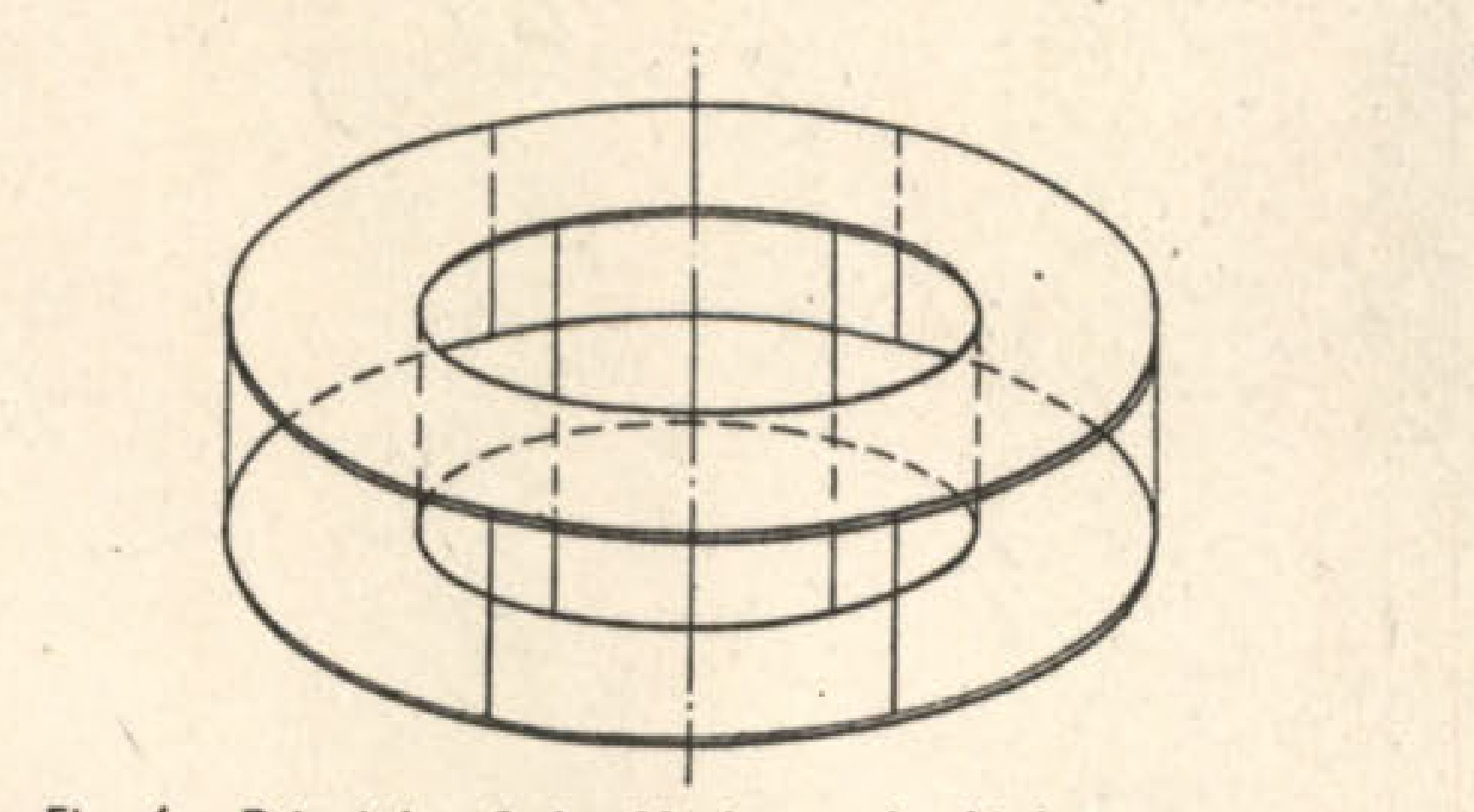
Fig. 4. Principle of the Huth annular-biplane system.
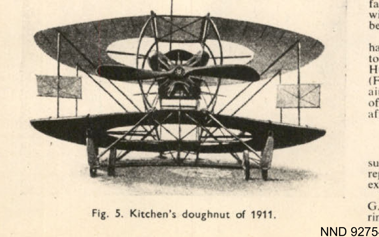
Fig. 5. Kitchen's doughnut of 1911.
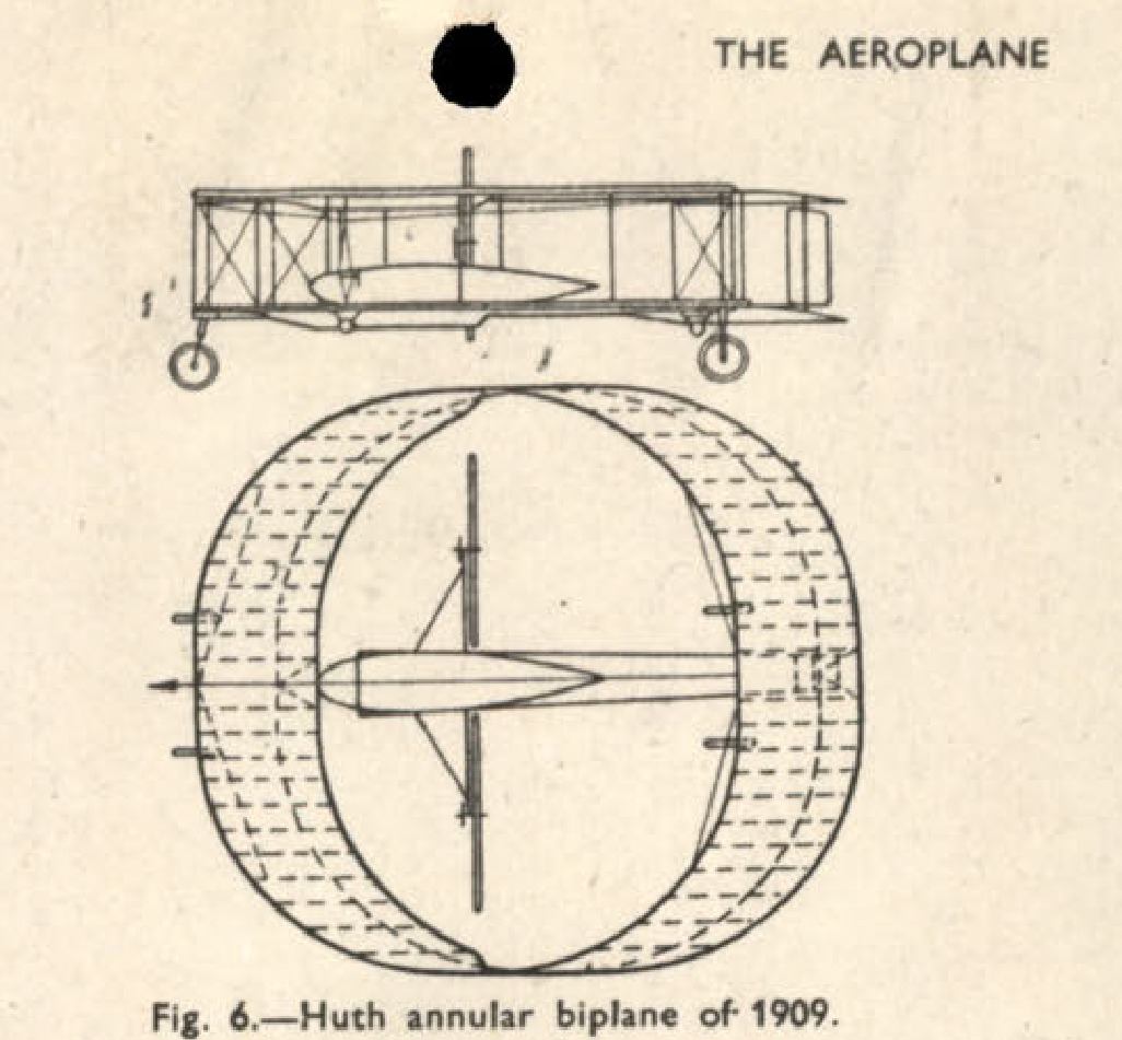
Fig. 6. Huth annular biplane of 1909.
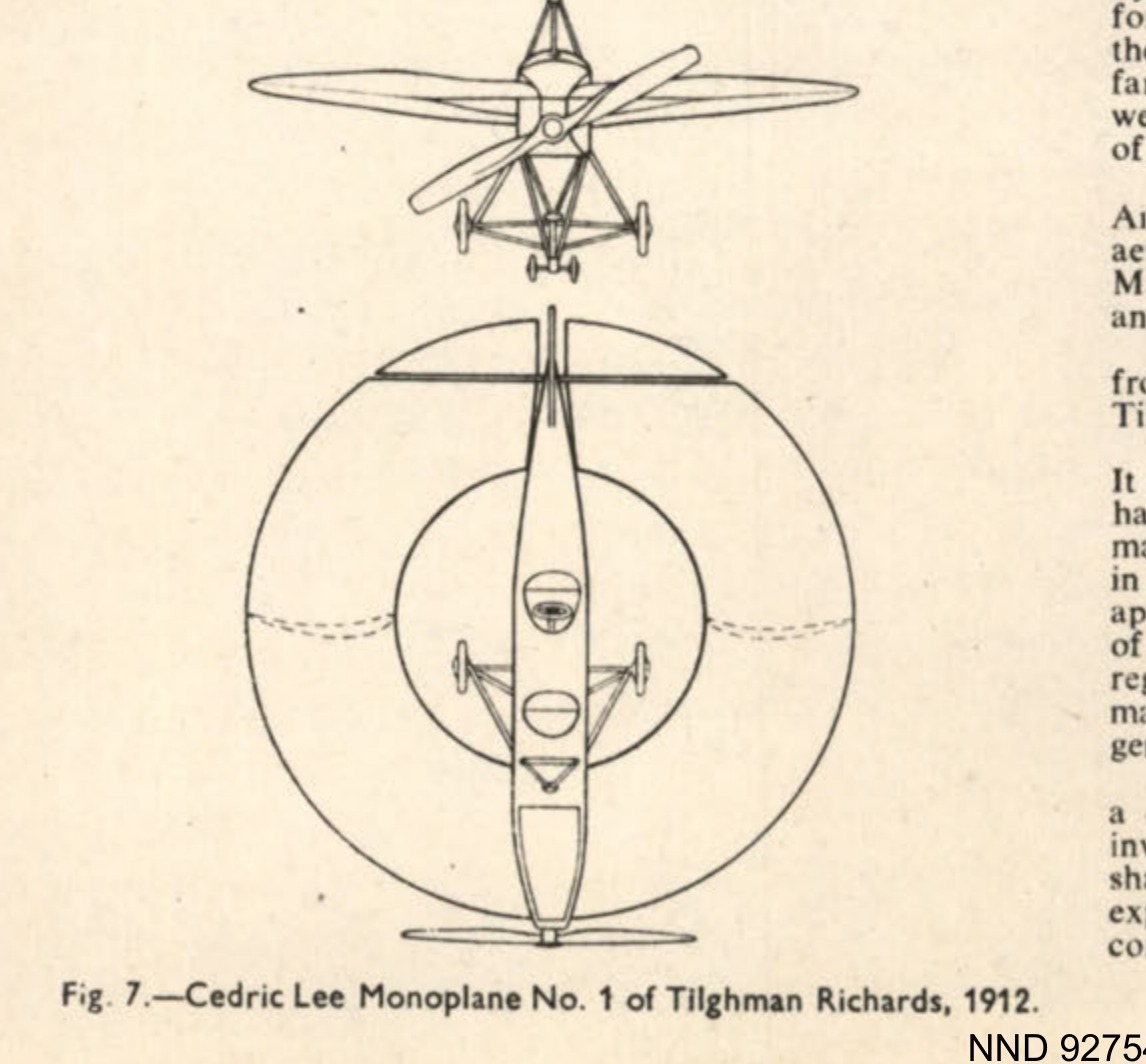
Fig. 7.-Cedric Lee Monoplane No. 1 of Tilghman Richards, 1912.
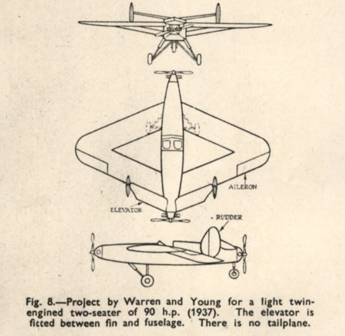
Fig. 8. Project by Warren and Young for a light twin-engined two-seater of 90 h.p. (1937). The elevator is fitted between fin and fuselage. There is no tailplane.
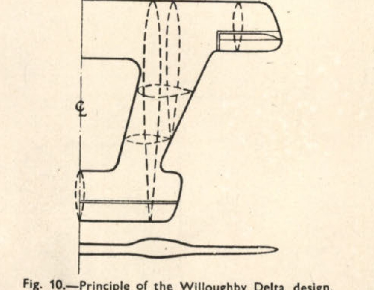
Fig. 10. Principle of the Willoughby Delta design.
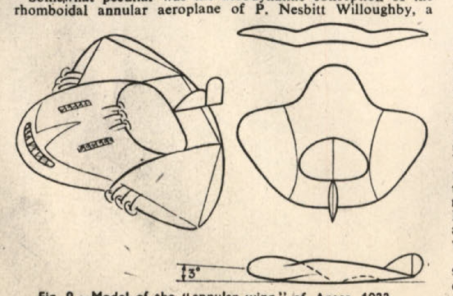
Fig. 9. Model of the "annular wing" of Antes, 1933.
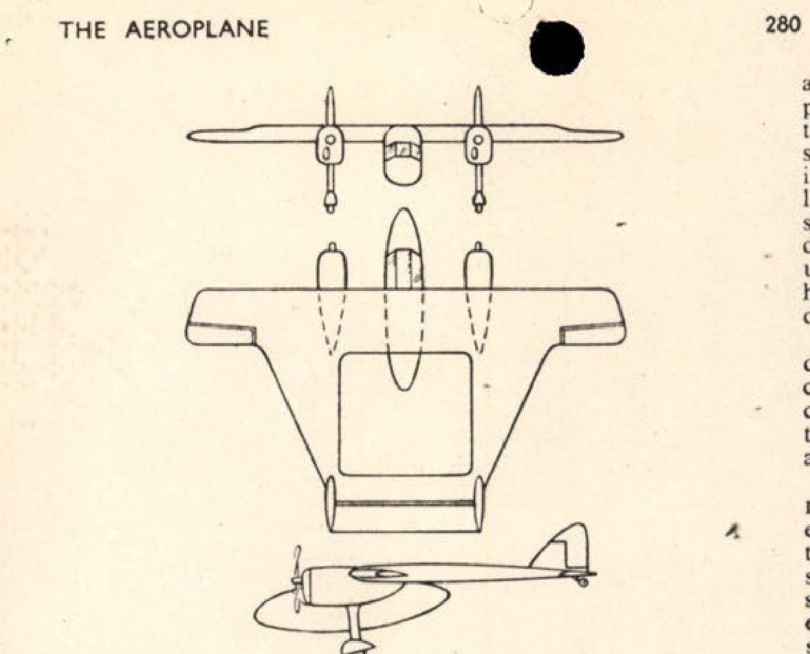
Fig. 11. Willoughby's "Delta 8" experimental monoplane of 1938.
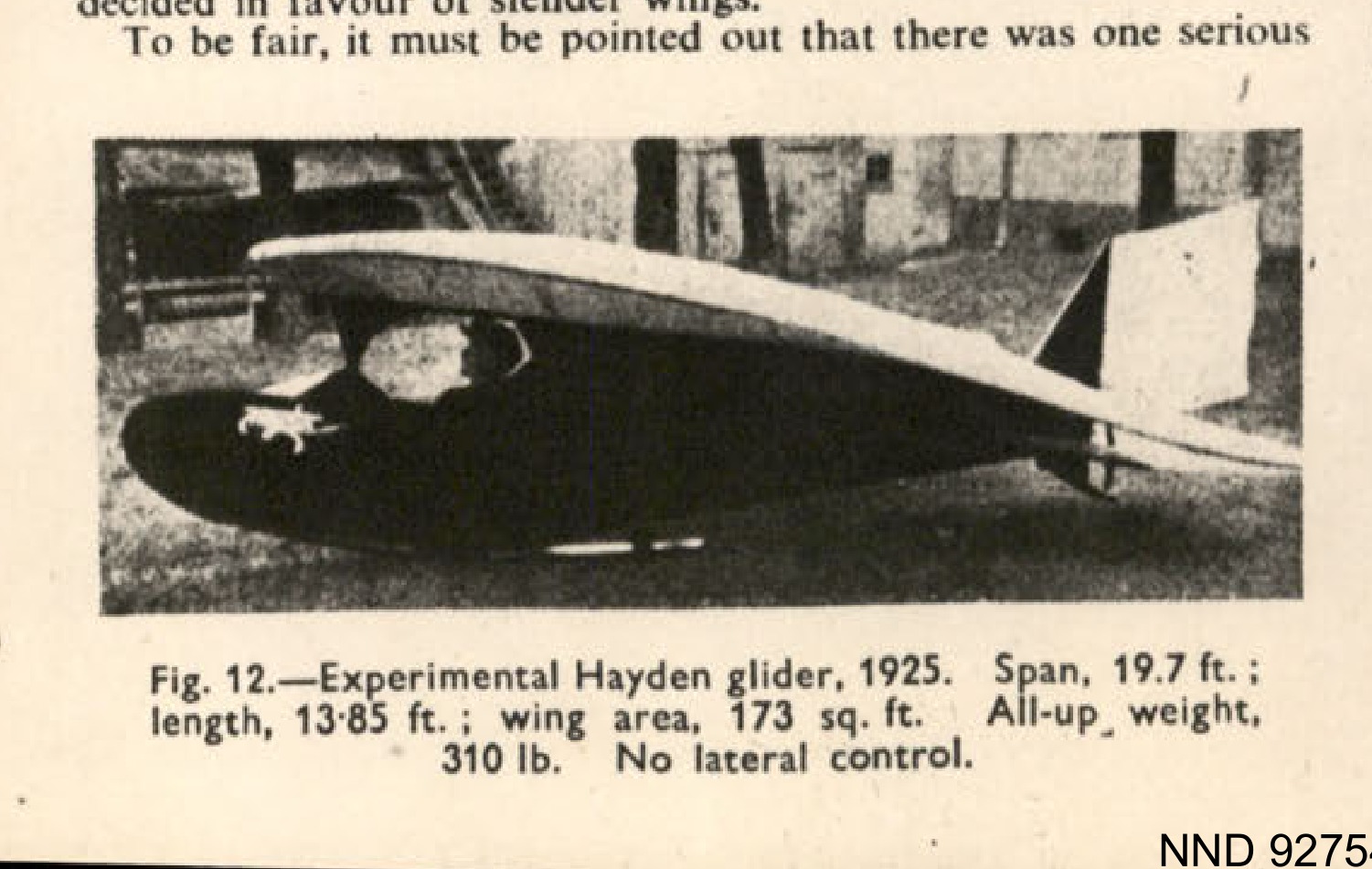
Fig. 12. Experimental Hayden glider, 1925. Span, 19.7 ft.; length, 13-85 ft.; wing area, 173 sq. ft. All-up, weight, 310 lb. No lateral control.
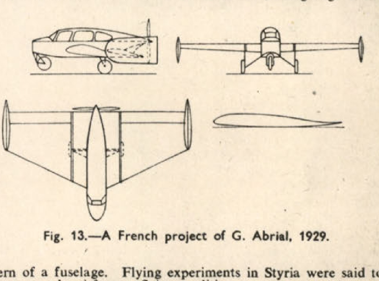
Fig. 13. A French project of G. Abrial, 1929.
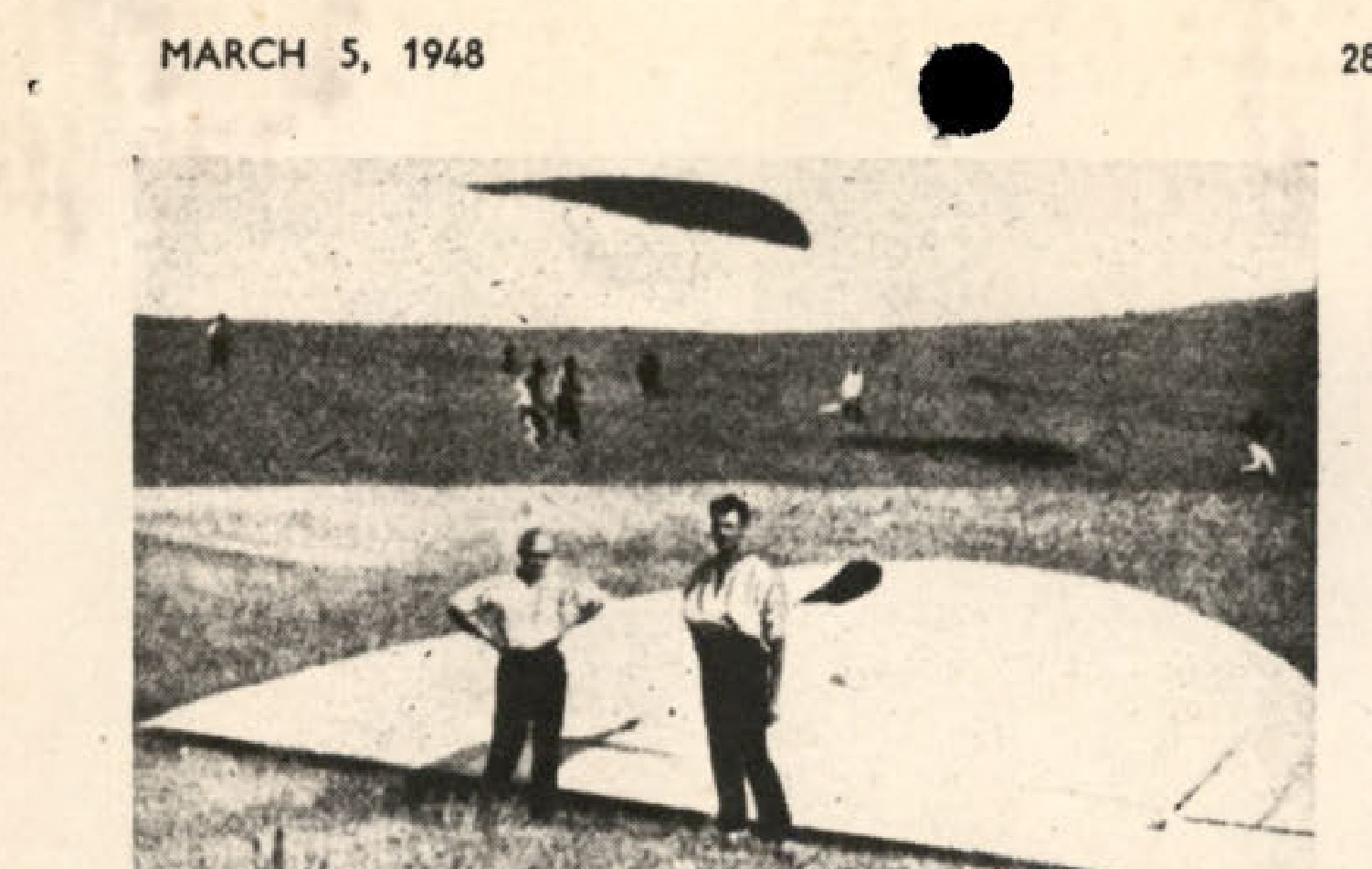
Fig. 14. A Russian parabola' glider of 1924.
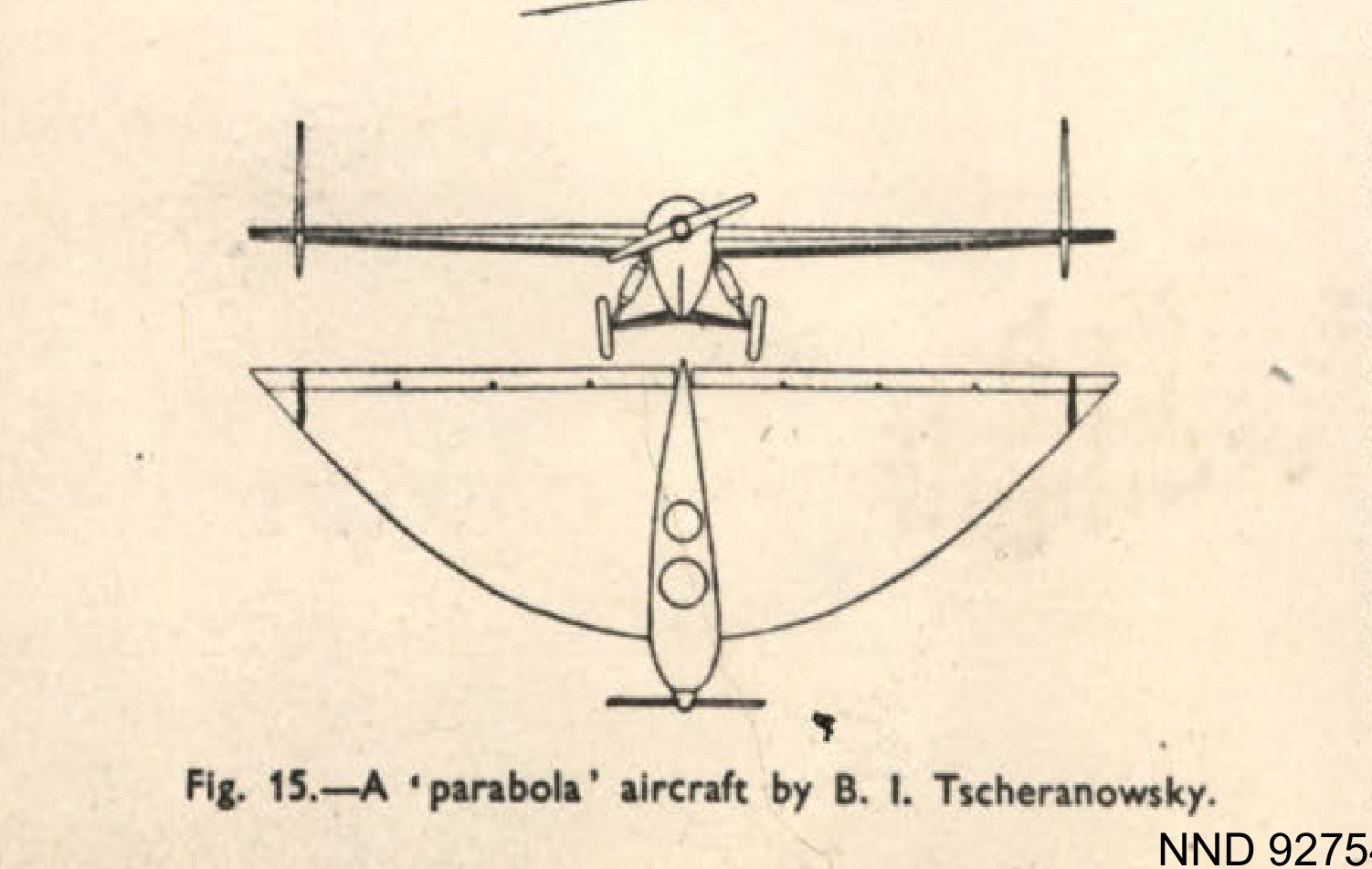
Fig. 15. A parabola' aircraft by B. I. Tscheranowsky.
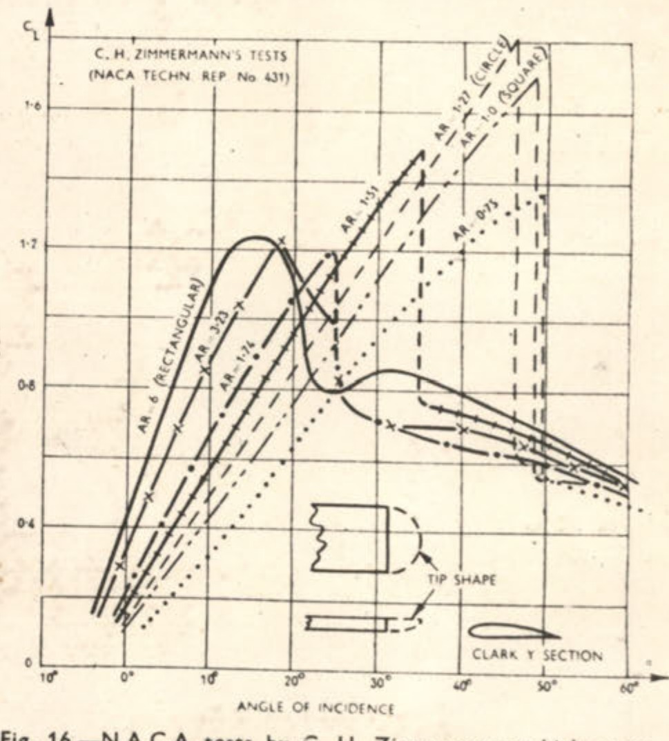
Fig. 16.-N.A.C.A. tests by C. H. Zimmermann which prove the extraordinary stalling qualities of disc wings.
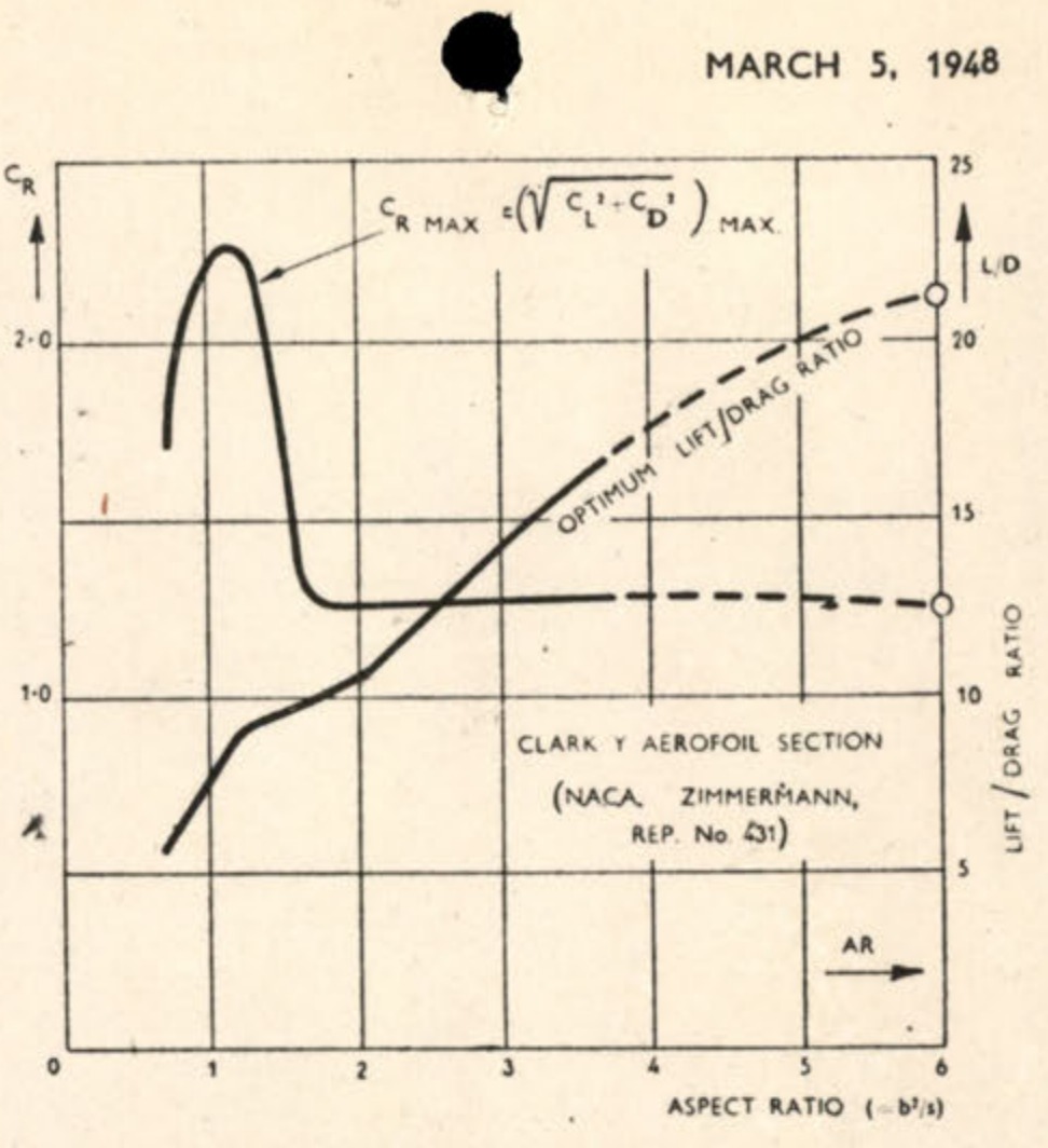
18. Further results from Zimmermann's tests shown here also indicate the advantages to be gained from disc wings.
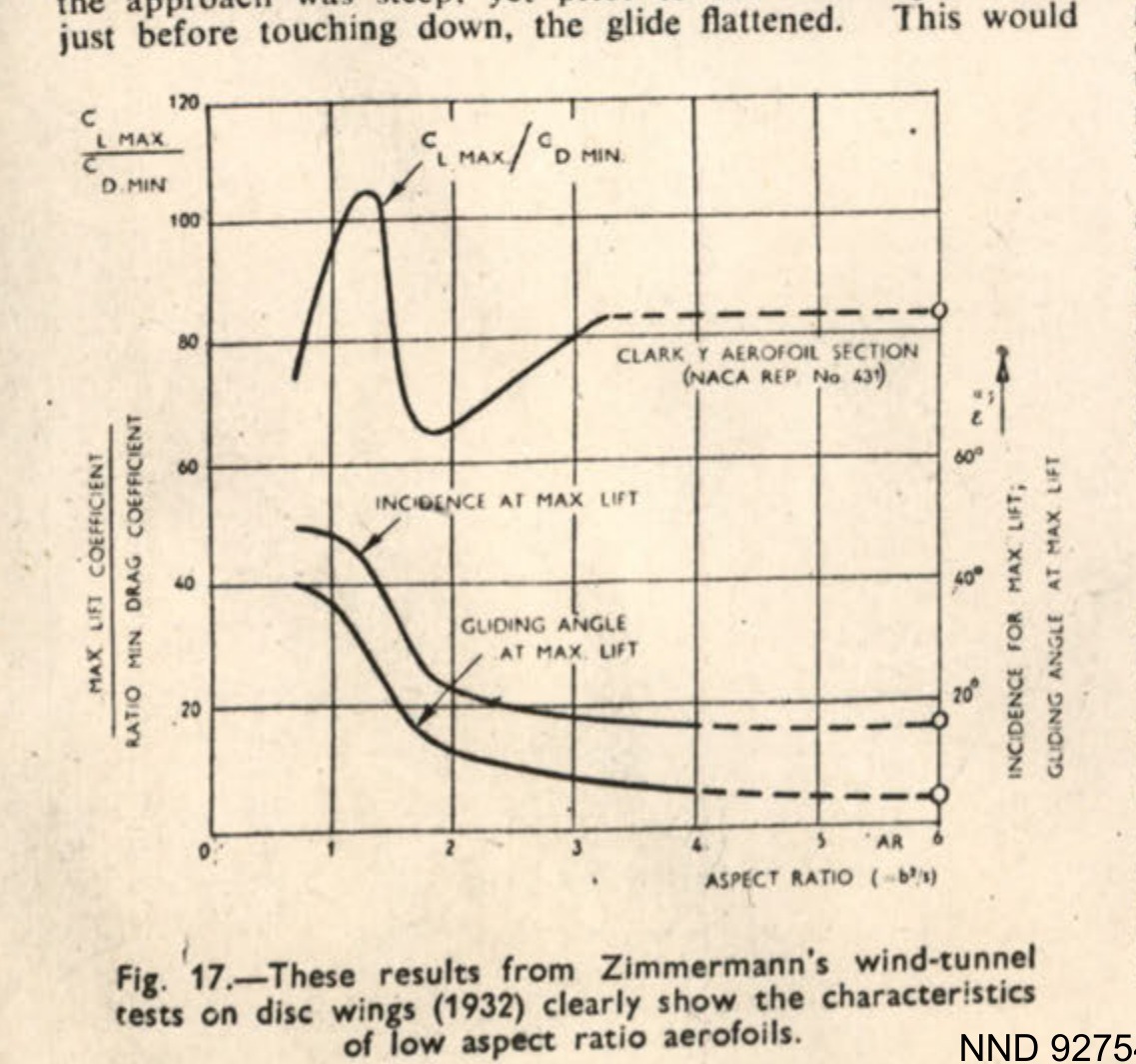
Fig. 17. These results from Zimmermann's wind-tunnel tests on disc wings (1932) clearly show the characteristics of low aspect ratio aerofoils.
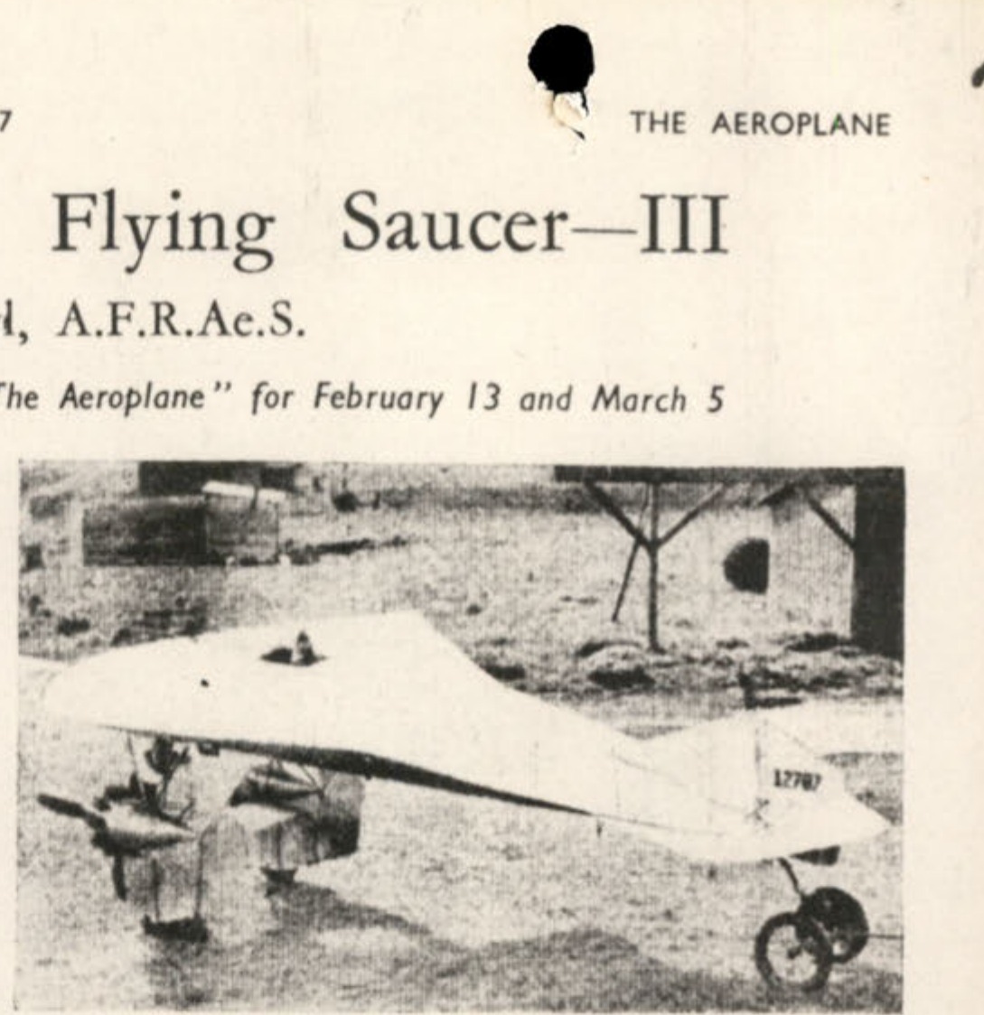
Fig. 19. An American "Flying Flapjack" with two engines. It crashed while under test (1938).
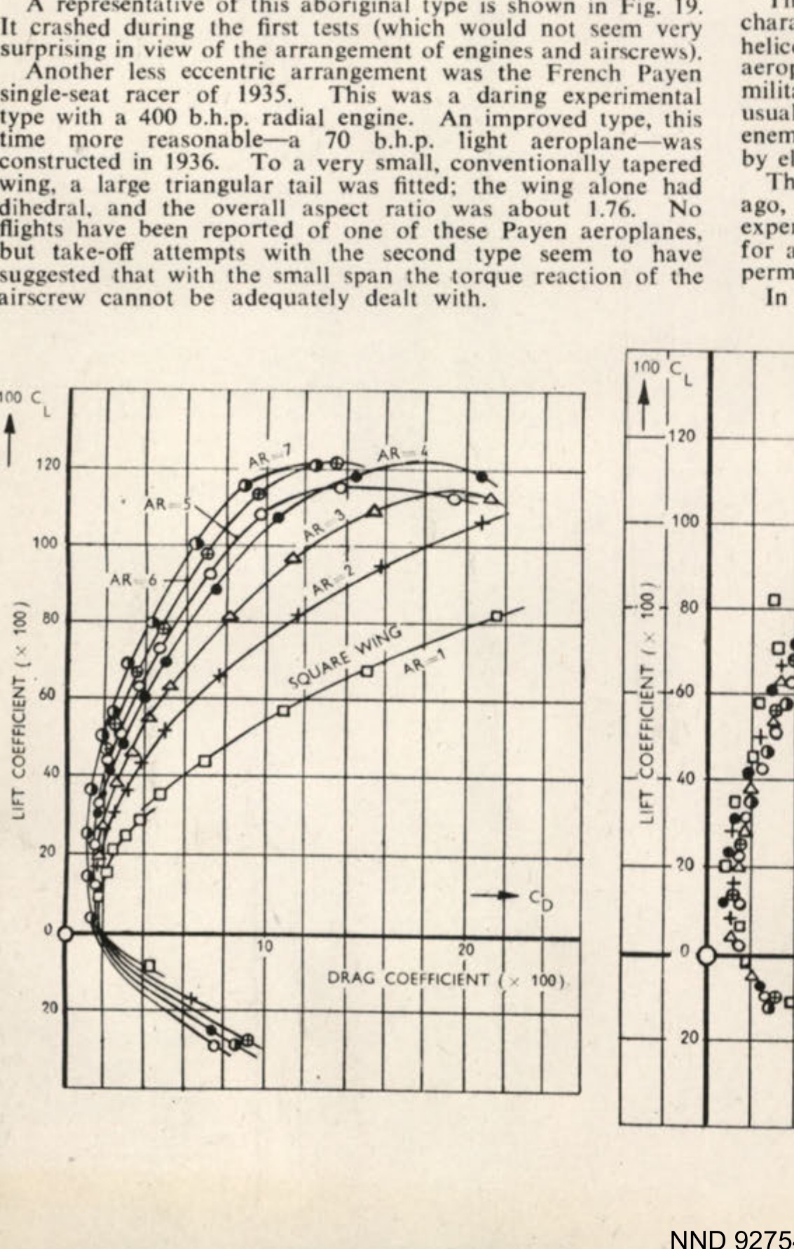
Chart showing lift coefficient vs drag coefficient for various aspect ratios (AR).
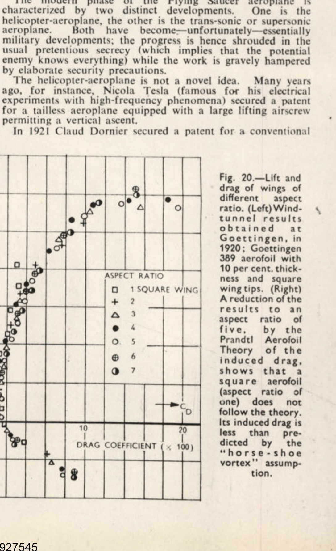
Fig. 20. Lift and drag of wings of different aspect ratio. (Left) Wind-tunnel results obtained at Goettingen, in 1920; Goettingen 389 aerofoil with 10 per cent. thickness and square wing tips. (Right) A reduction of the results to an aspect ratio of five, by the Prandtl Aerofoil Theory of the induced drag, shows that a square aerofoil (aspect ratio of one) does not follow the theory. Its induced drag is less than predicted by the "horse-shoe vortex" assumption.
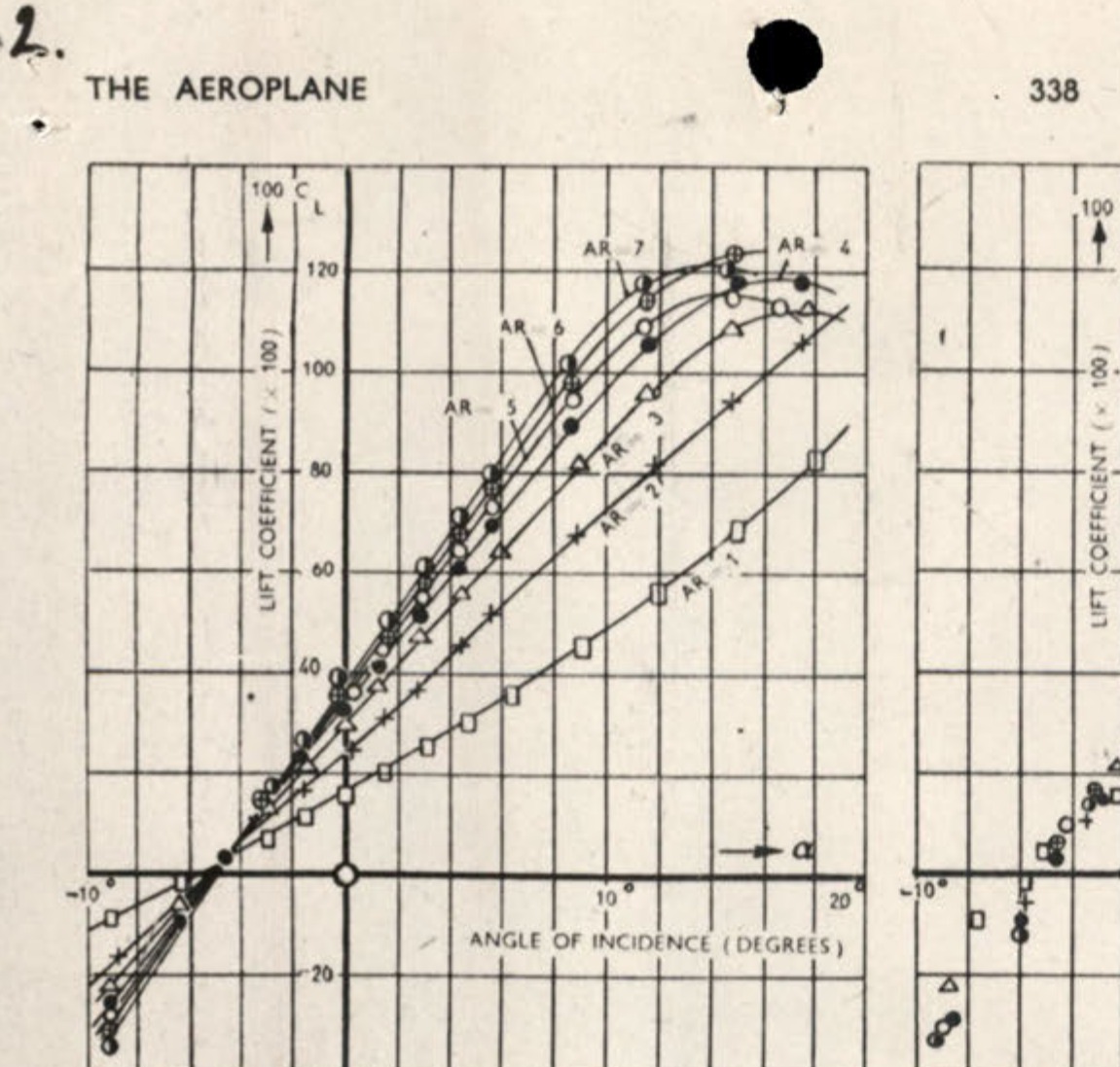
Chart showing lift coefficient vs angle of incidence for various aspect ratios (AR).
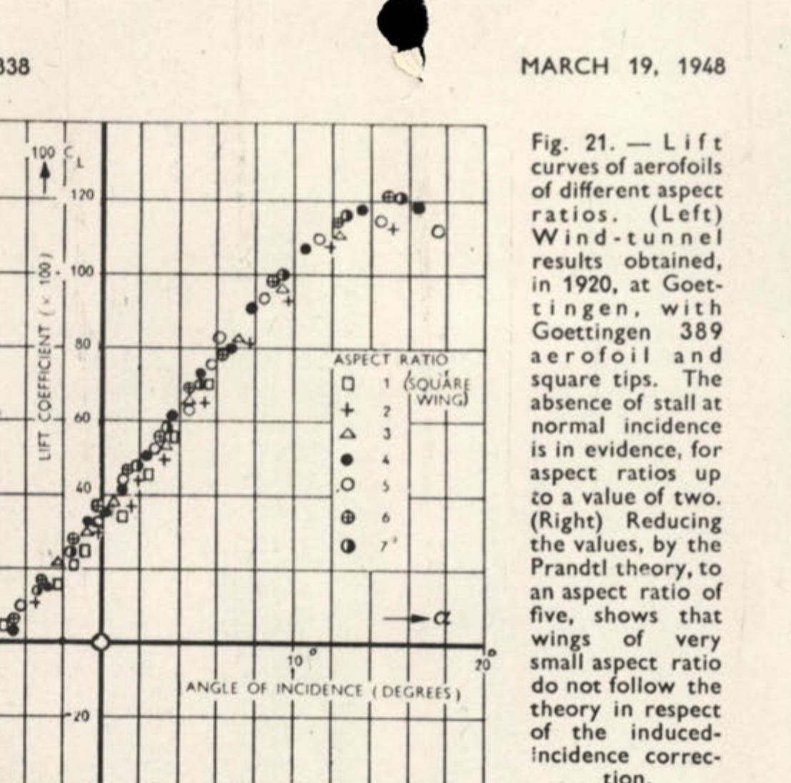
Fig. 21. Lift curves of aerofoils of different aspect ratios. (Left) Wind-tunnel results obtained, in 1920, at Goettingen, with Goettingen 389 aerofoil and square tips. The absence of stall at normal incidence is in evidence, for aspect ratios up to a value of two. (Right) Reducing the values, by the Prandtl theory, to an aspect ratio of five, shows that wings of very small aspect ratio do not follow the theory in respect of the induced-incidence correction.
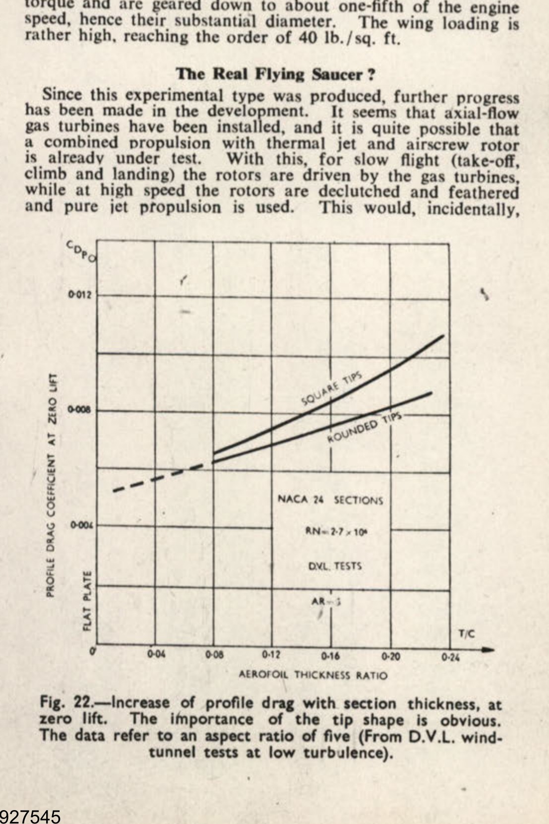
Fig. 22. Increase of profile drag with section thickness, at zero lift. The importance of the tip shape is obvious. The data refer to an aspect ratio of five (From D.V.L. wind-tunnel tests at low turbulence).
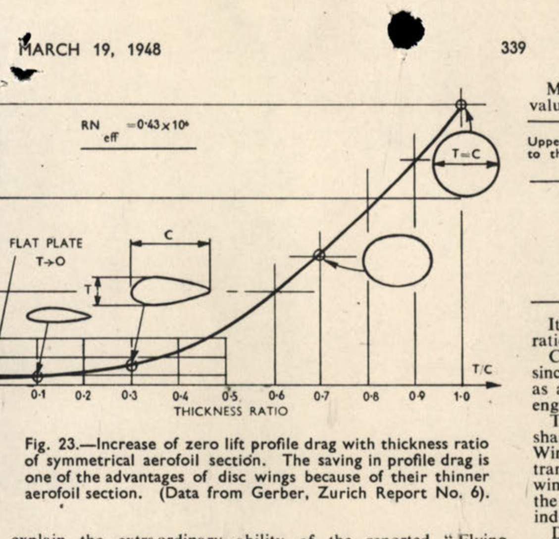
Fig. 23. Increase of zero lift profile drag with thickness ratio of symmetrical aerofoil section. The saving in profile drag is one of the advantages of disc wings because of their thinner aerofoil section. (Data from Gerber, Zurich Report No. 6).
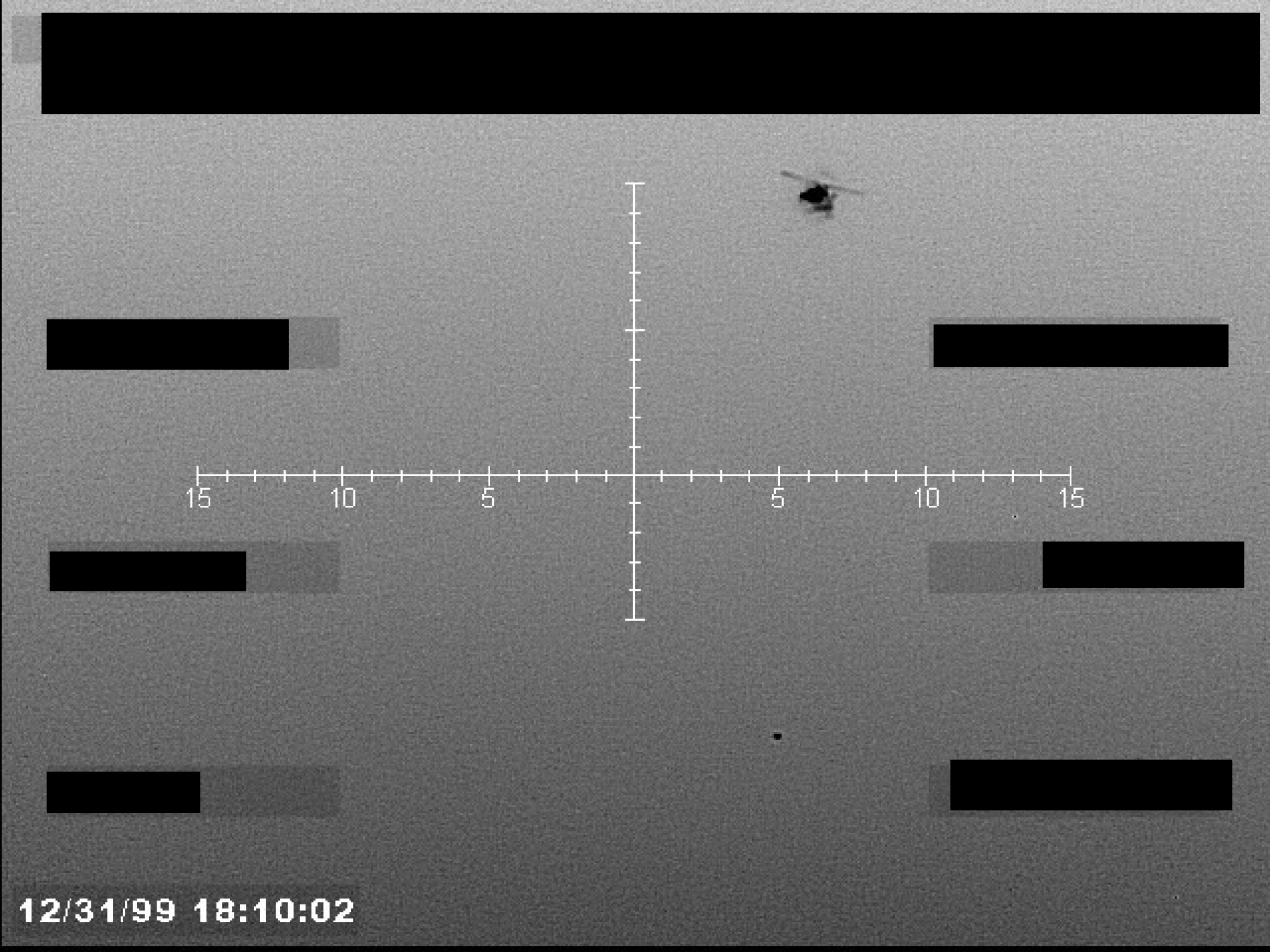
Grayscale sensor footage showing a central crosshair, a small object in the upper right, and a timestamp in the lower left. Several data fields are redacted.
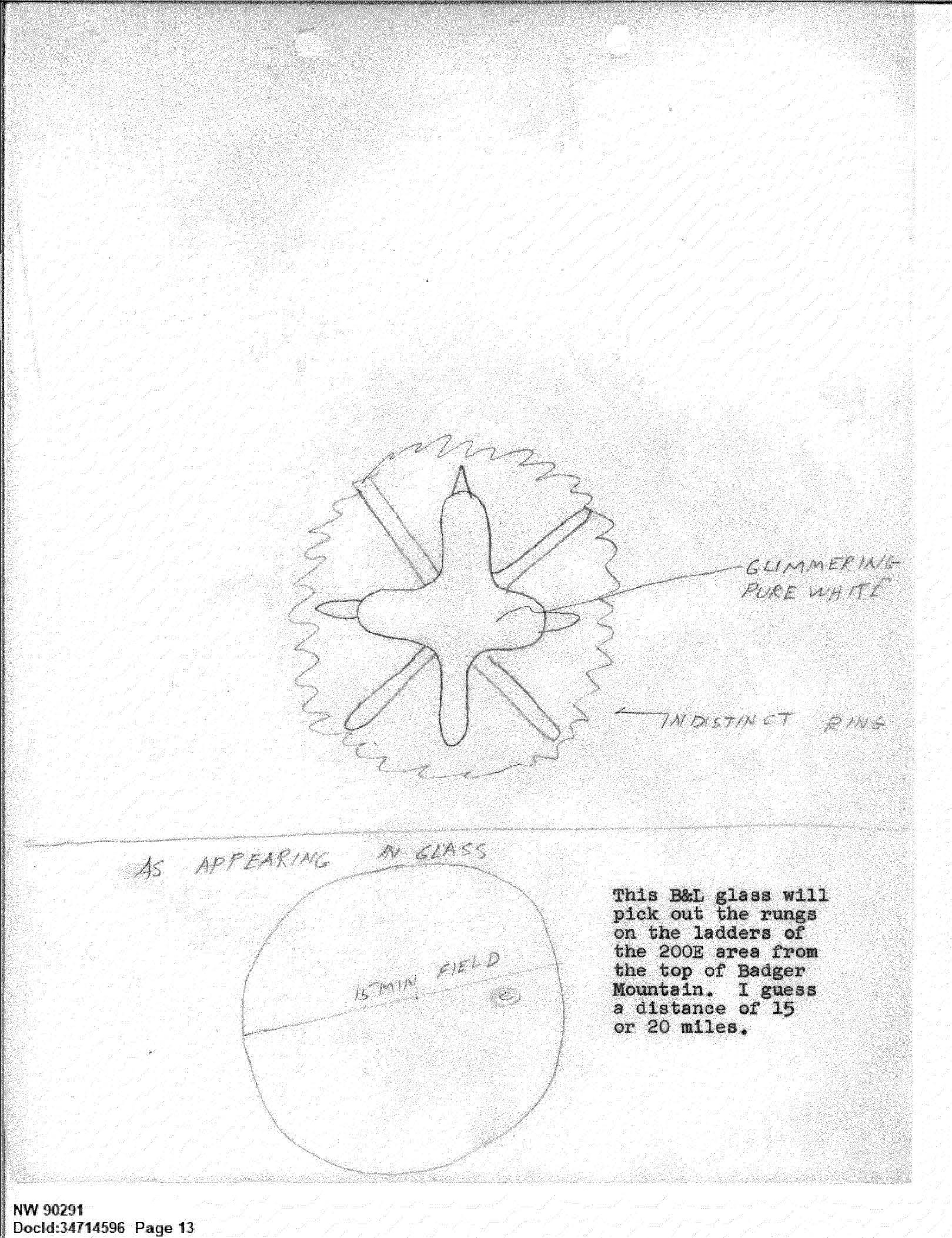
Sketch of a shimmering, cross-shaped object with a surrounding ring.
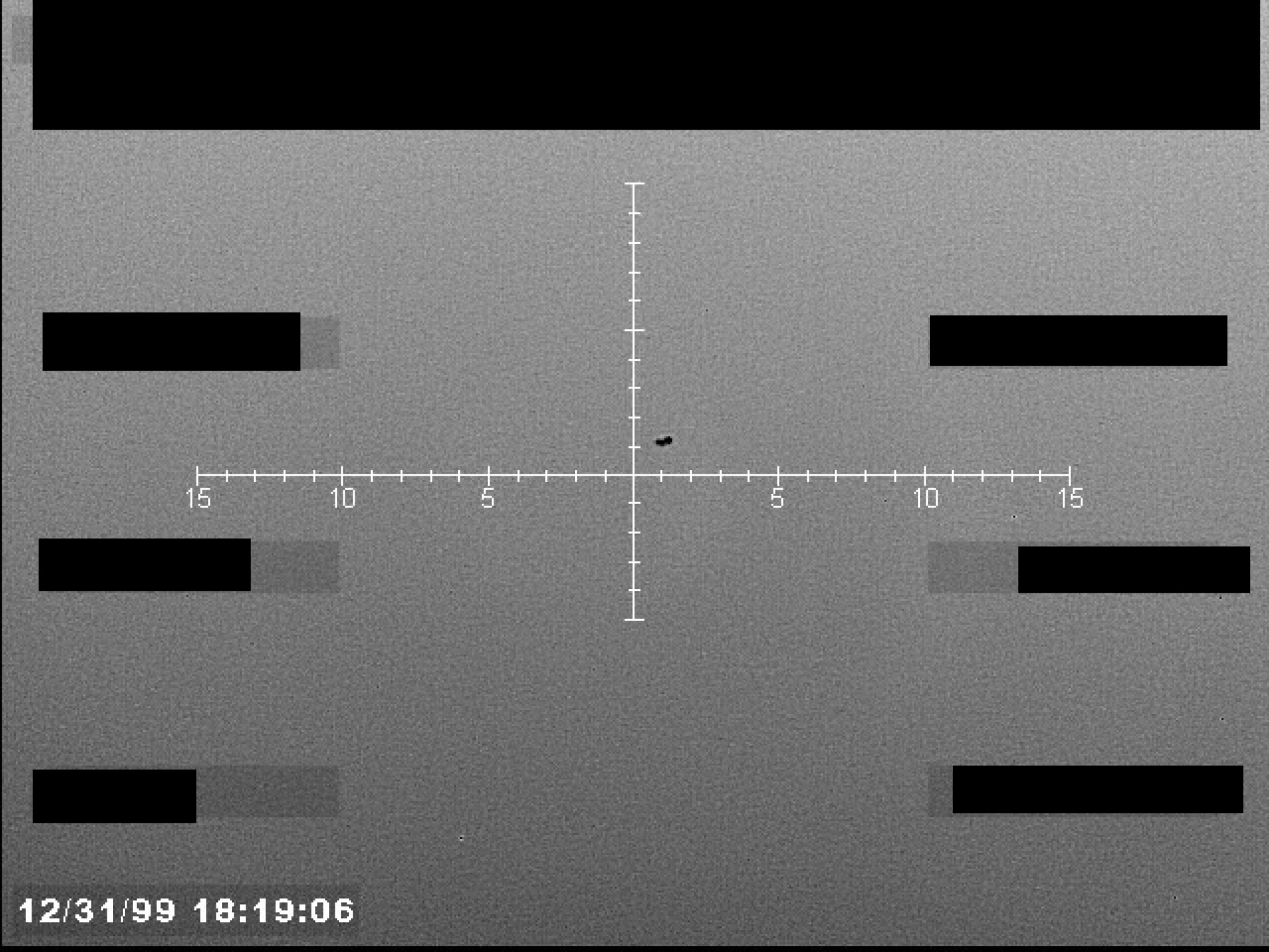
Sensor display with a central crosshair targeting a small, dark object. Numerical markings are visible along the horizontal axis of the crosshair. A timestamp is present in the lower-left corner.
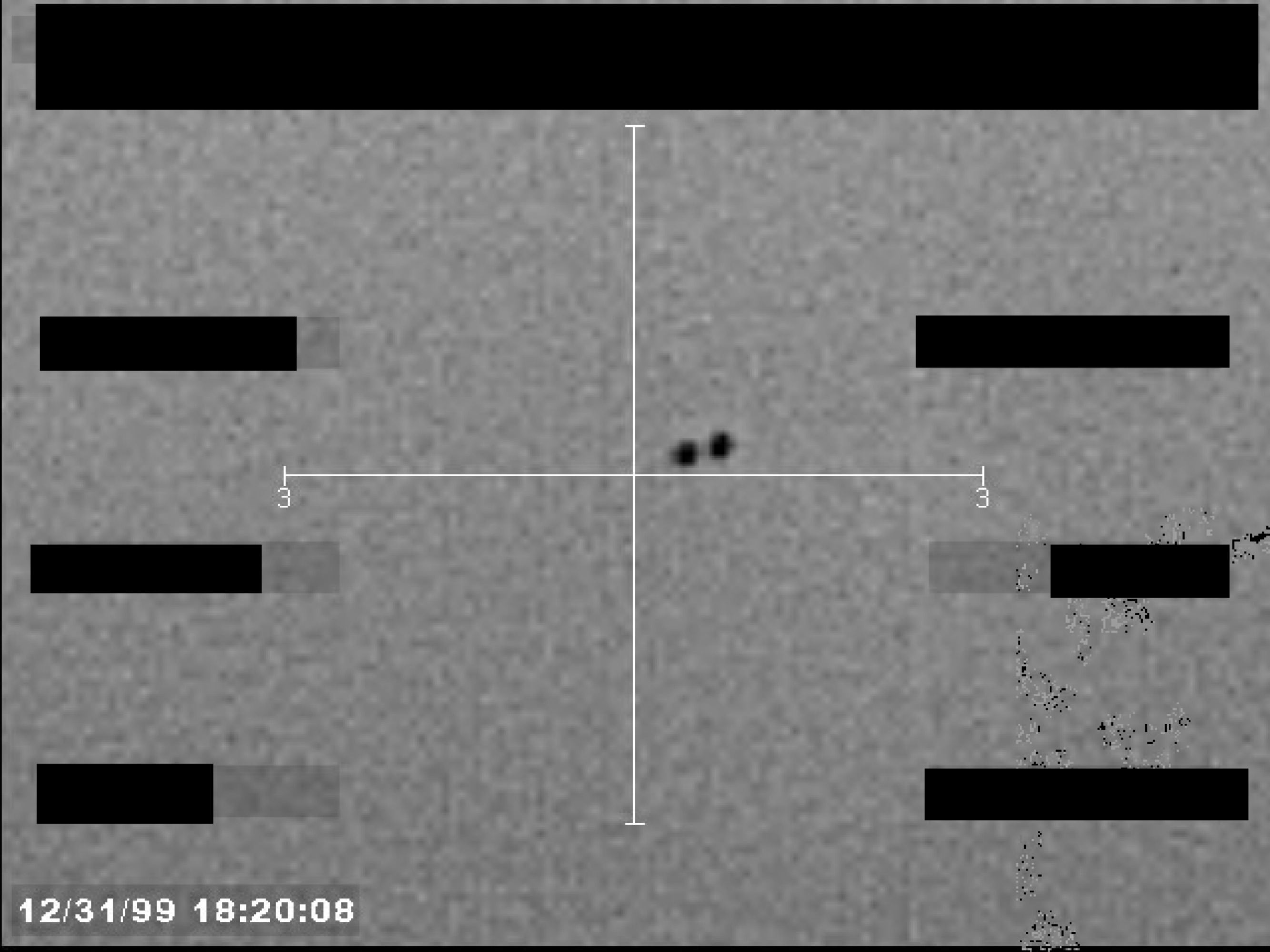
Sensor footage frame showing a crosshair targeting two small, dark objects. Several data fields are redacted.
Map of the United States showing locations of flying object sightings.
Fig. 1
Fig. 2
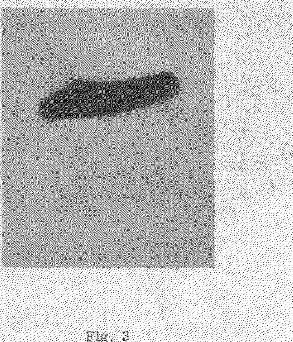
Fig. 3

Fig. 4
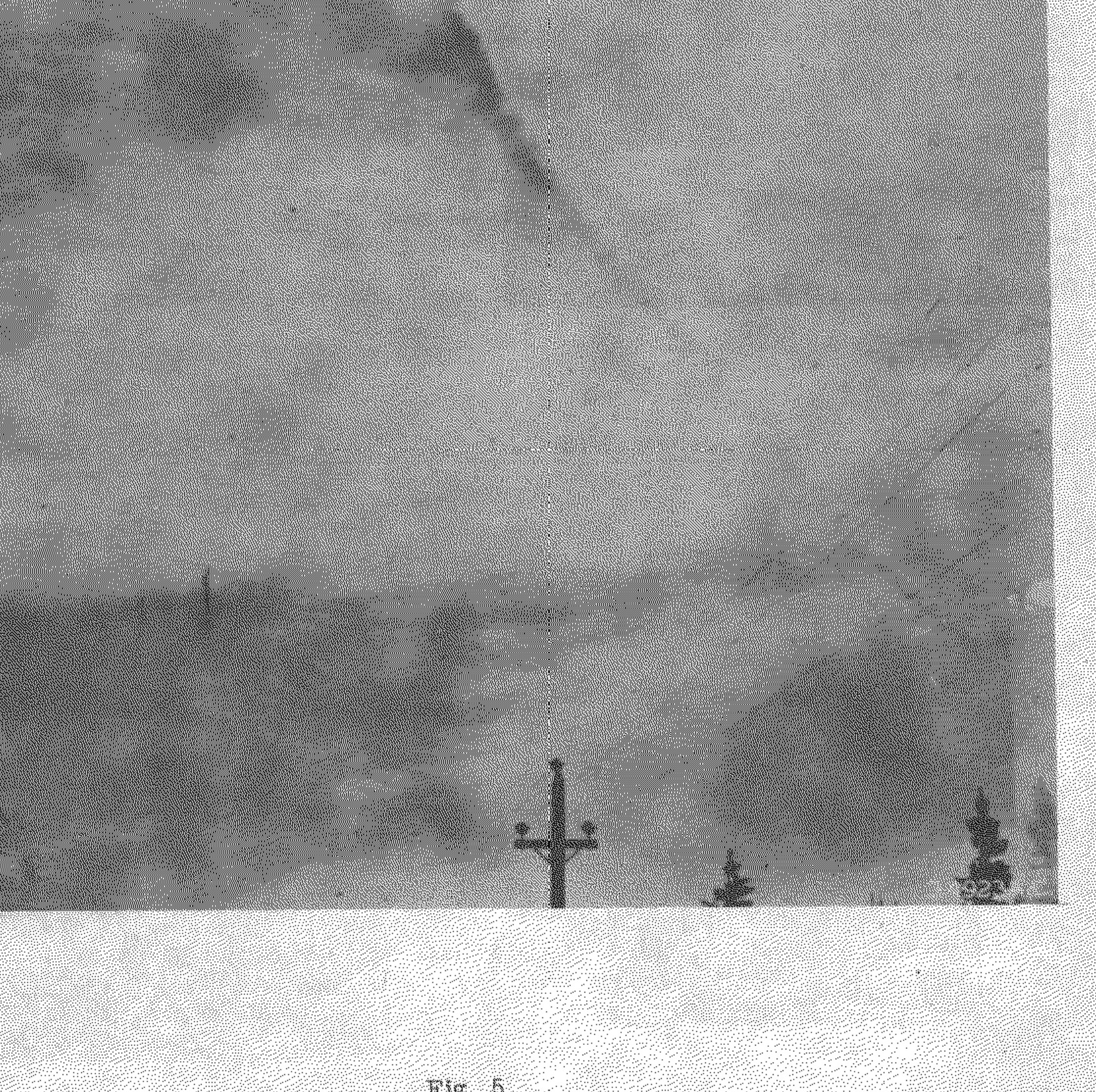
Fig. 5
Fig. 6
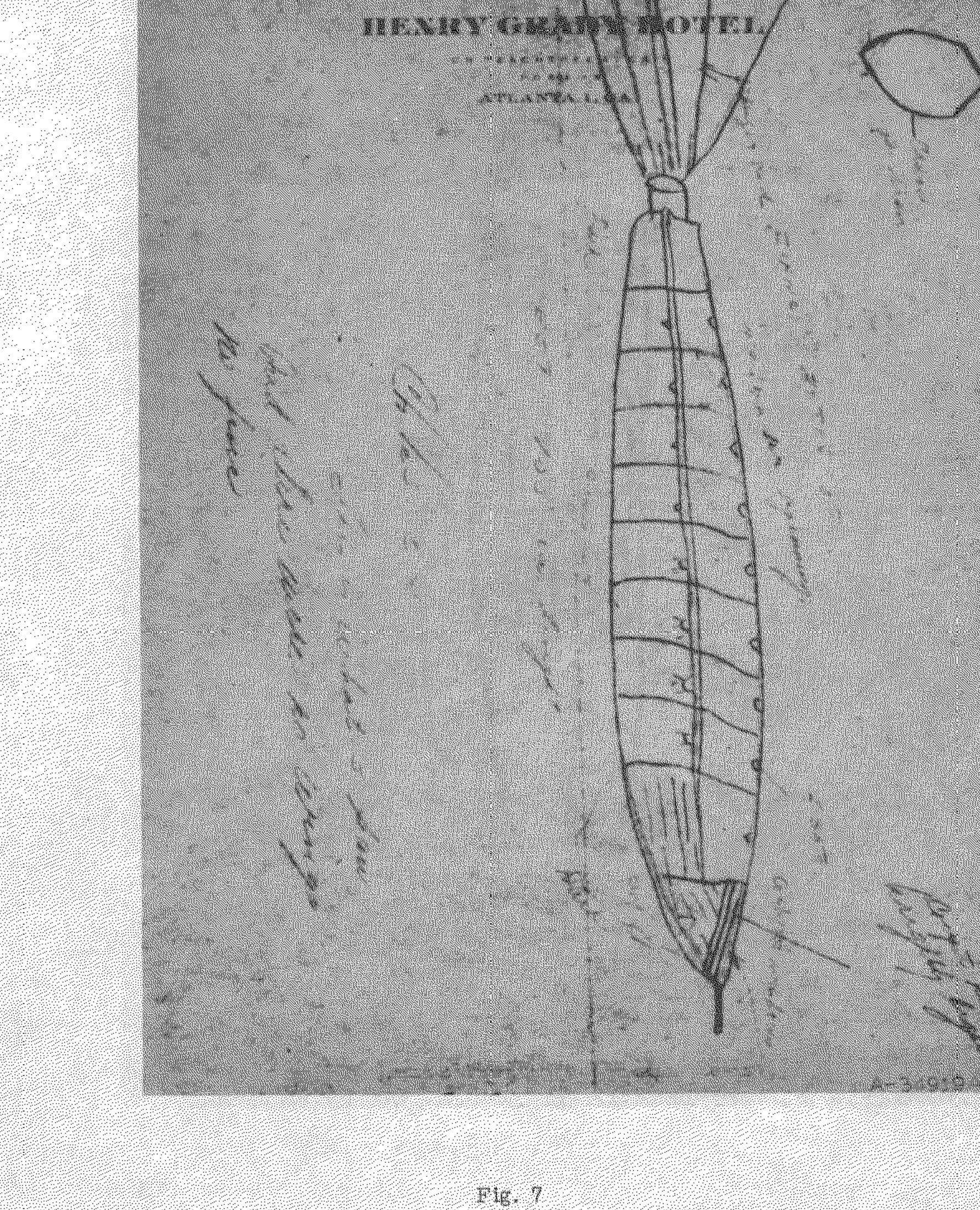
Sketch of a cigar-shaped object on Henry Grady Hotel letterhead.
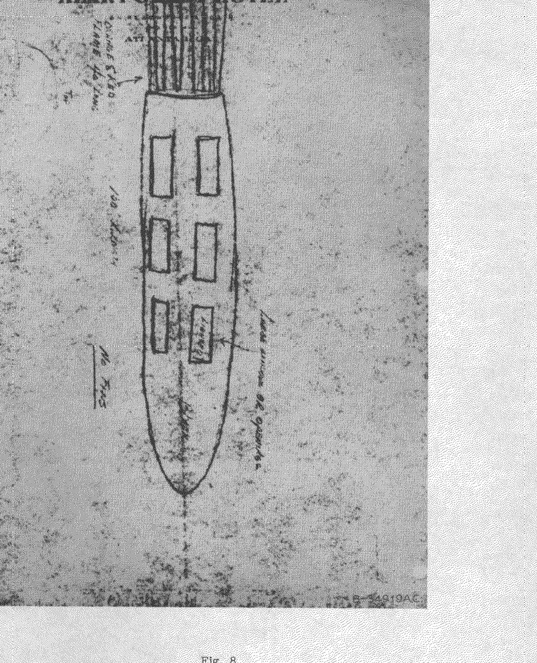
Sketch of a cigar-shaped object on Henry Grady Hotel letterhead.
Fig. 1
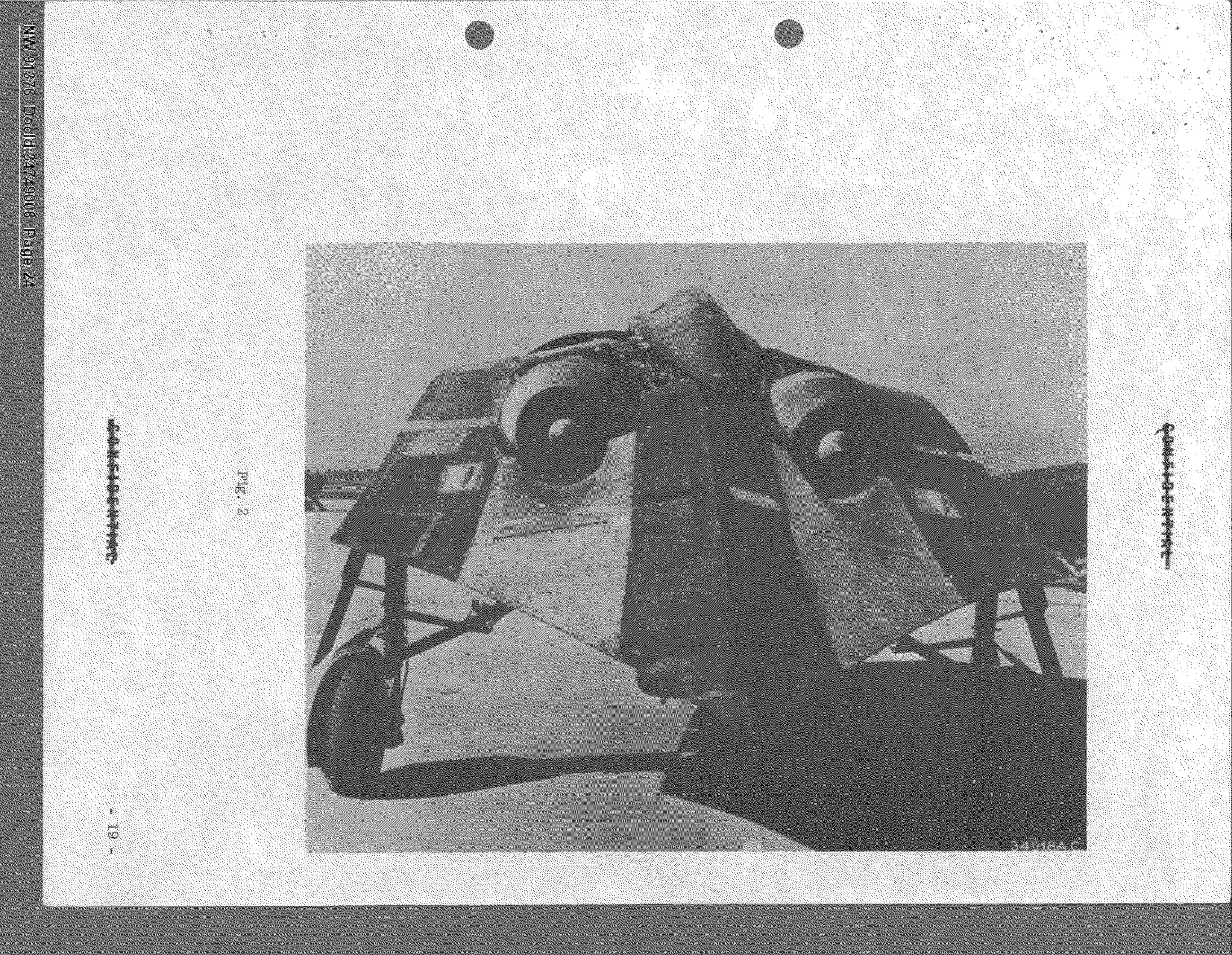
Photograph of a Horten flying wing aircraft on a runway.
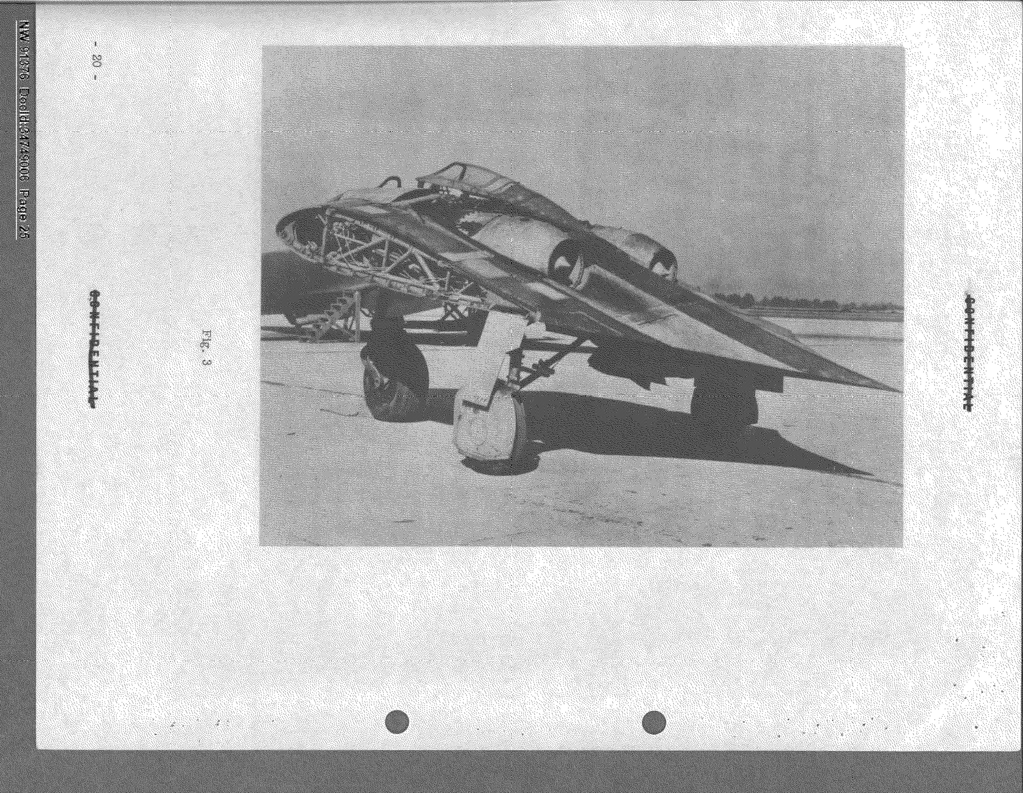
Photograph of a Horten flying wing aircraft on a runway.
Fig. 4
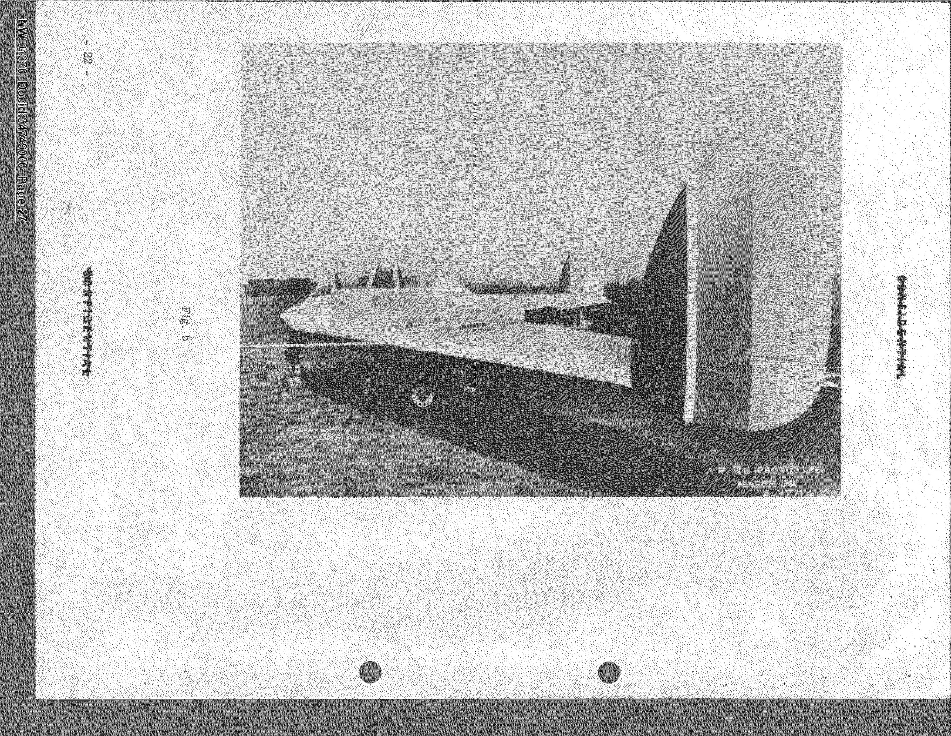
Photograph of the A.W. 52G Prototype aircraft on a runway.
Fig. 6
Fig. 7
Fig. 8
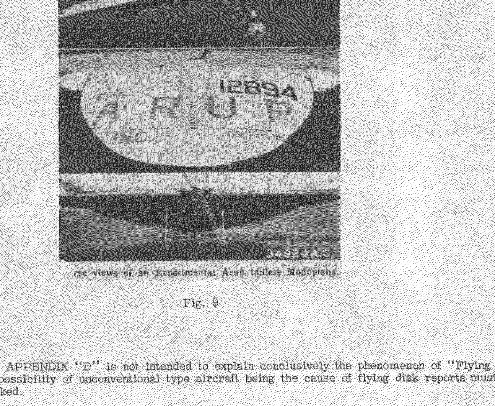
Fig. 9
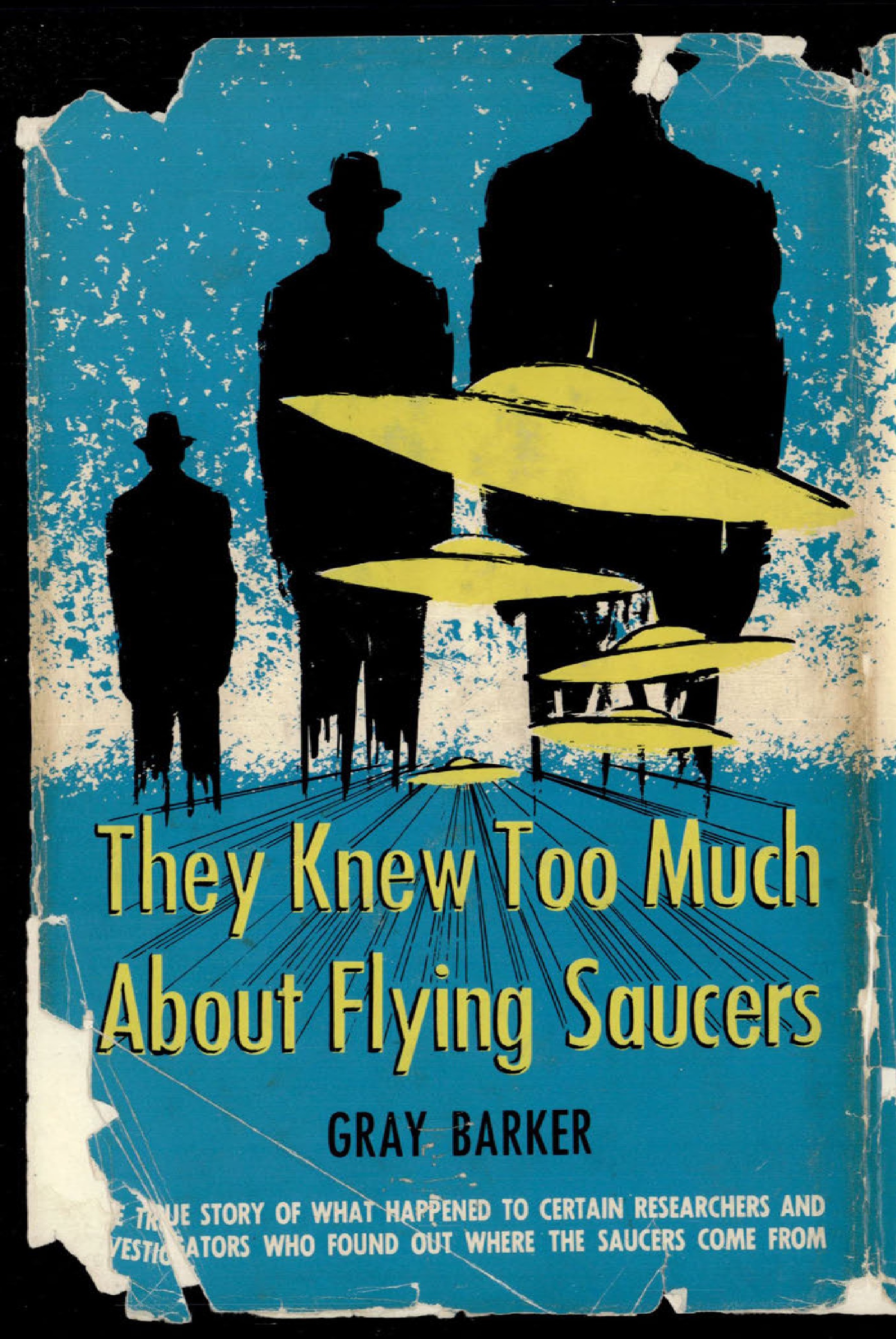
Illustration of men in suits looking at flying saucers.
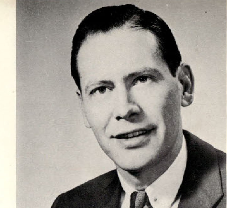
Headshot photograph of Gray Barker.
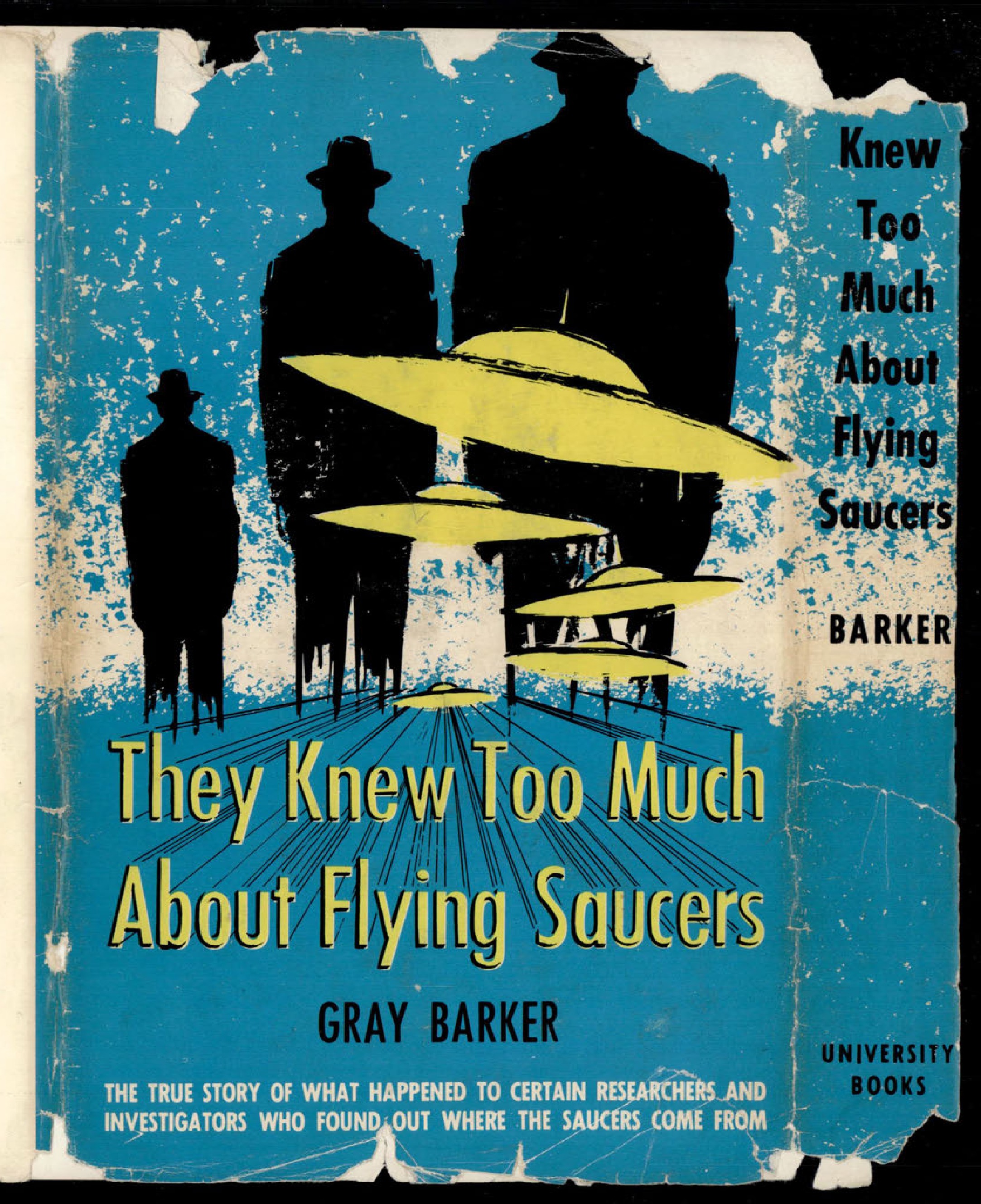
Illustration of men in suits looking at flying saucers, continued from front cover.
NASA logo
Manned Spacecraft Center logo
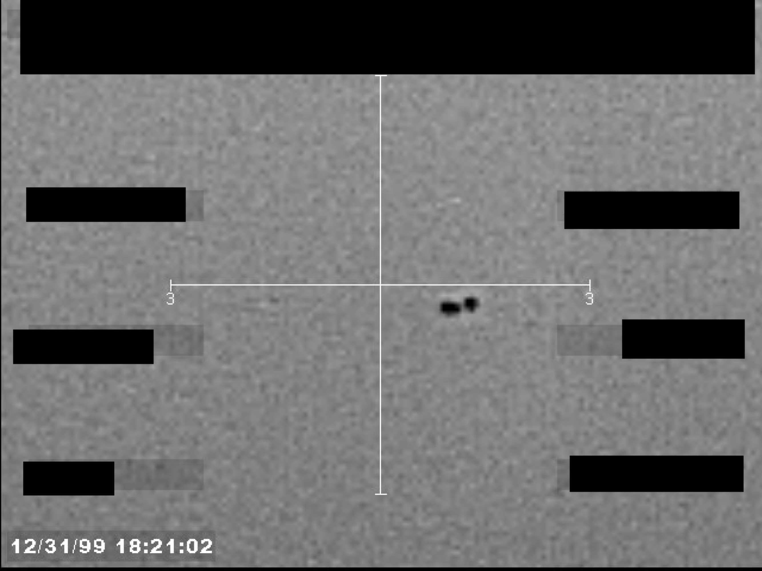
Sensor display showing two small, dark objects near a central crosshair, with a timestamp and redacted data fields.
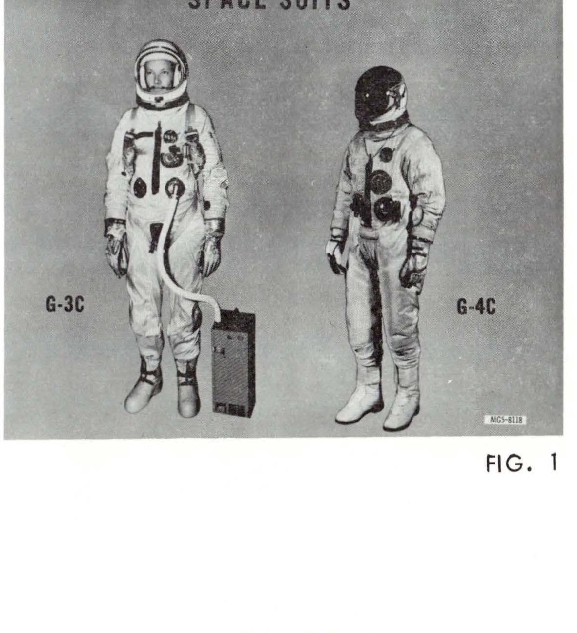
SPACE SUITS showing G-3C and G-4C suits side by side
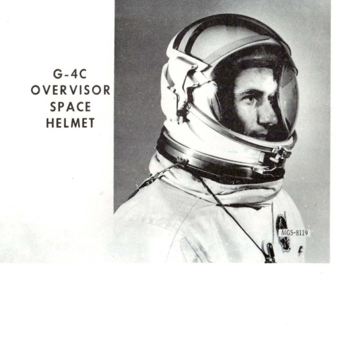
G-4C OVERVISOR SPACE HELMET showing astronaut wearing helmet
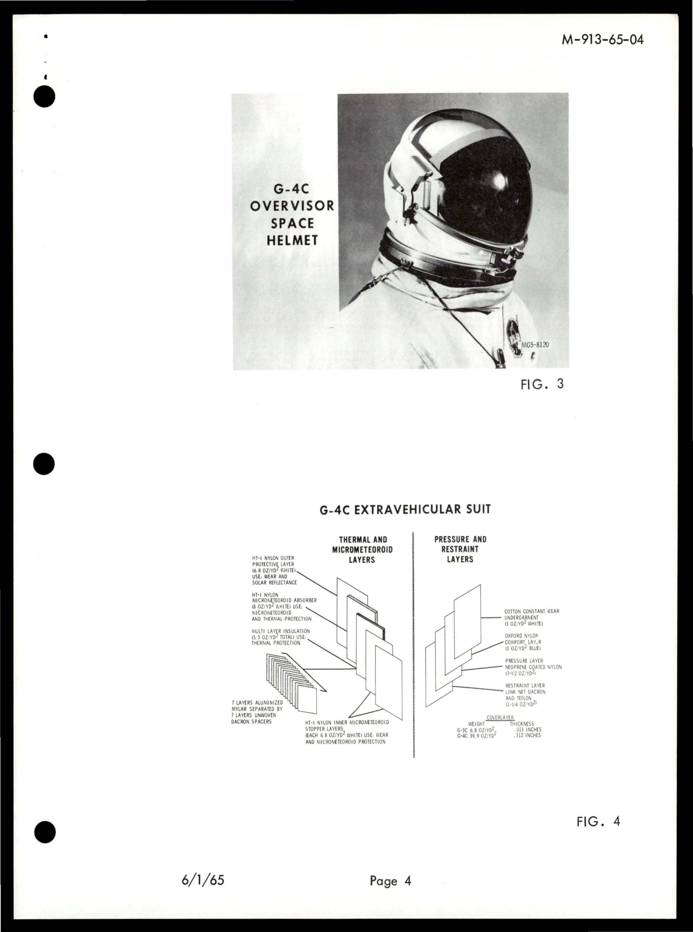
G-4C OVERVISOR SPACE HELMET
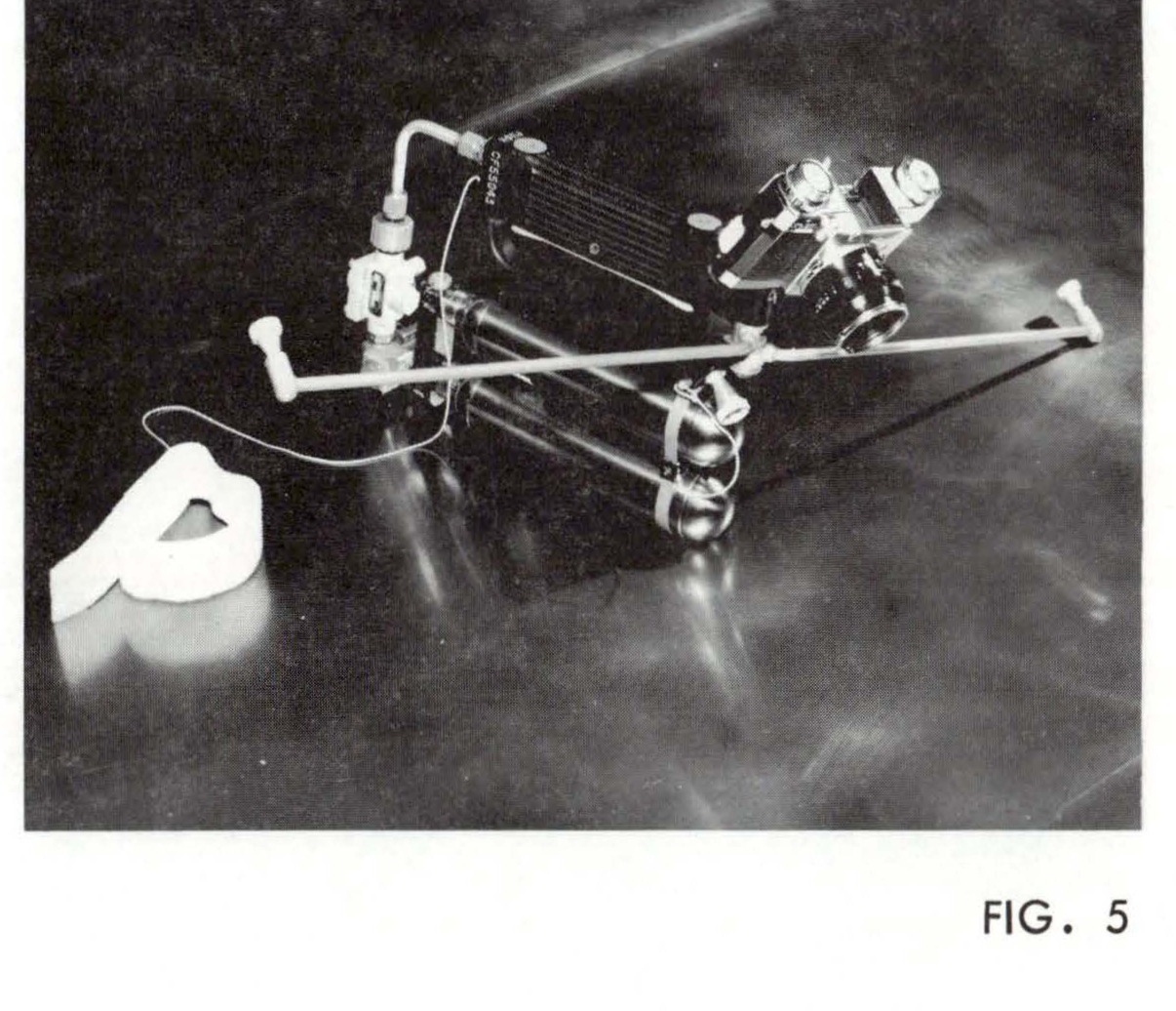
Zero g Integral Propulsion (ZIP) Unit with forward and aft firing nozzles
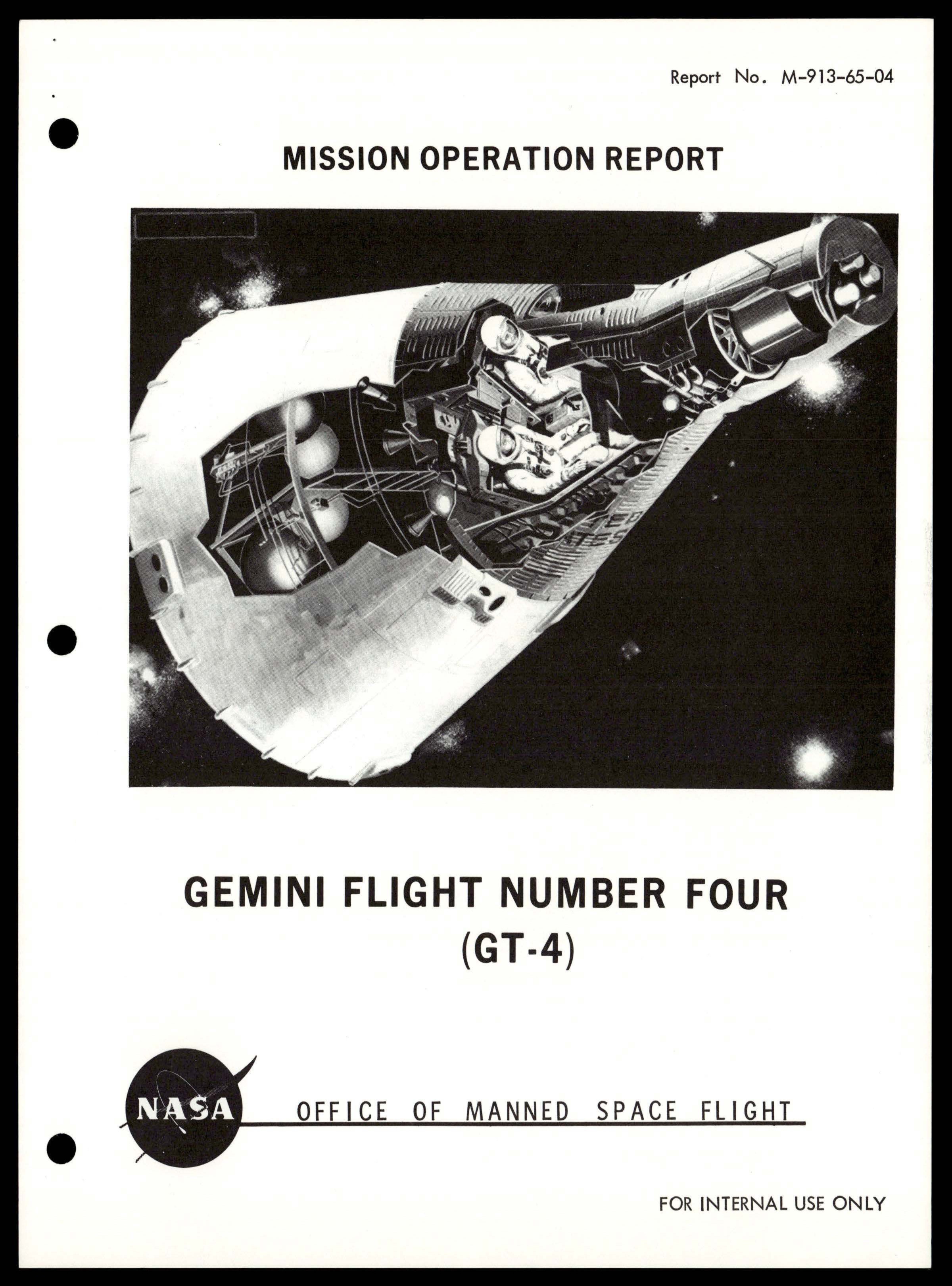
Cutaway illustration of Gemini spacecraft showing interior crew compartment and equipment
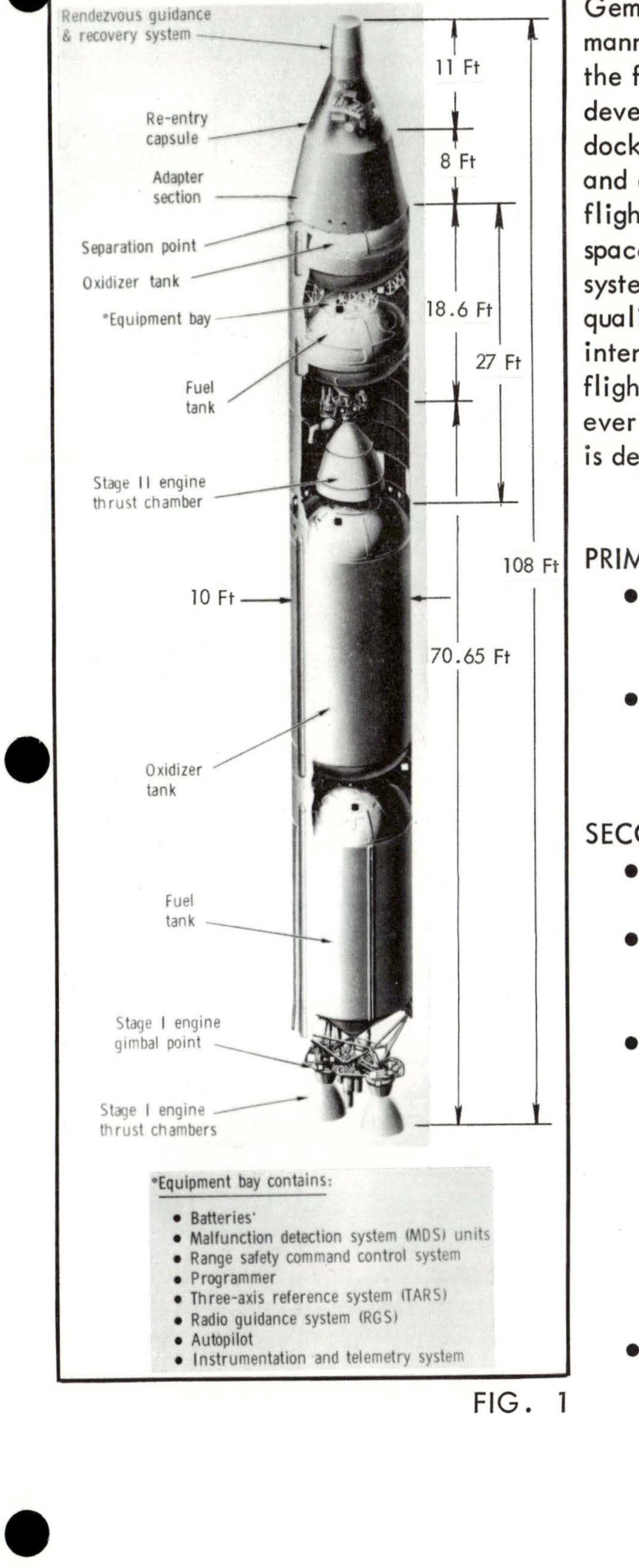
FIG. 1 - Labeled diagram of Gemini spacecraft showing components including rendezvous guidance & recovery system, re-entry capsule, adapter section, separation point, oxidizer tank, equipment bay, fuel tank, Stage II engine thrust chamber, Stage I engine gimbal point, and Stage I engine thrust chambers. Equipment bay contains: Batteries, Malfunction detection system (MDS) units, Range safety command control set, Programmer, Three-axis reference system (TARS), Reaction control system (RCS), Autopilot, Instrumentation and telemetry system.
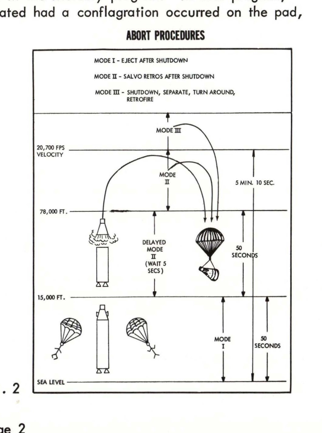
Abort procedures diagram showing three modes with altitude and time parameters, including velocity markers at 29,700 FPS and 78,000 FT, with delayed mode and retrofire sequences
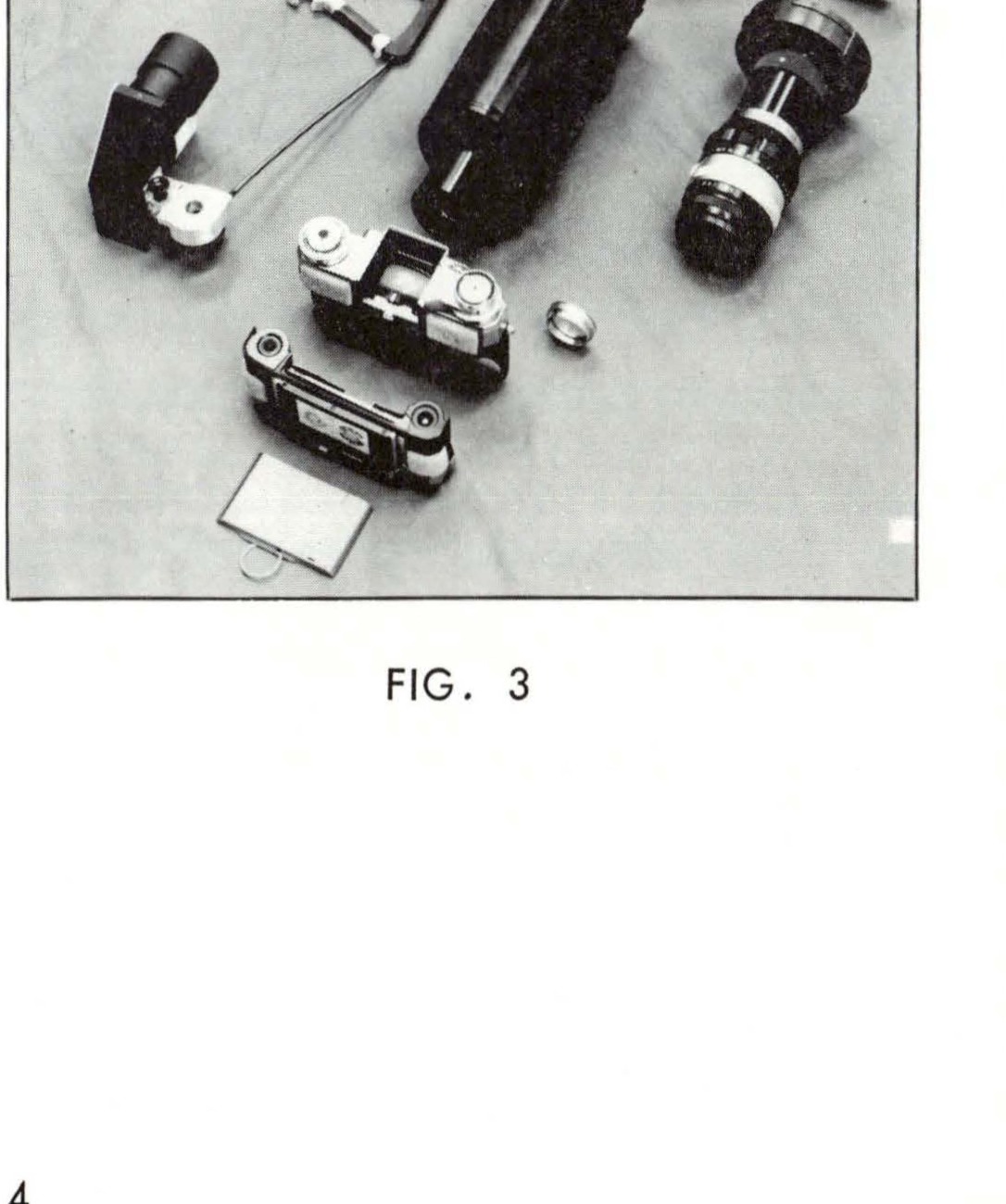
D-1 BASIC OBJECT PHOTOGRAPHY - photographic equipment including cameras and lenses
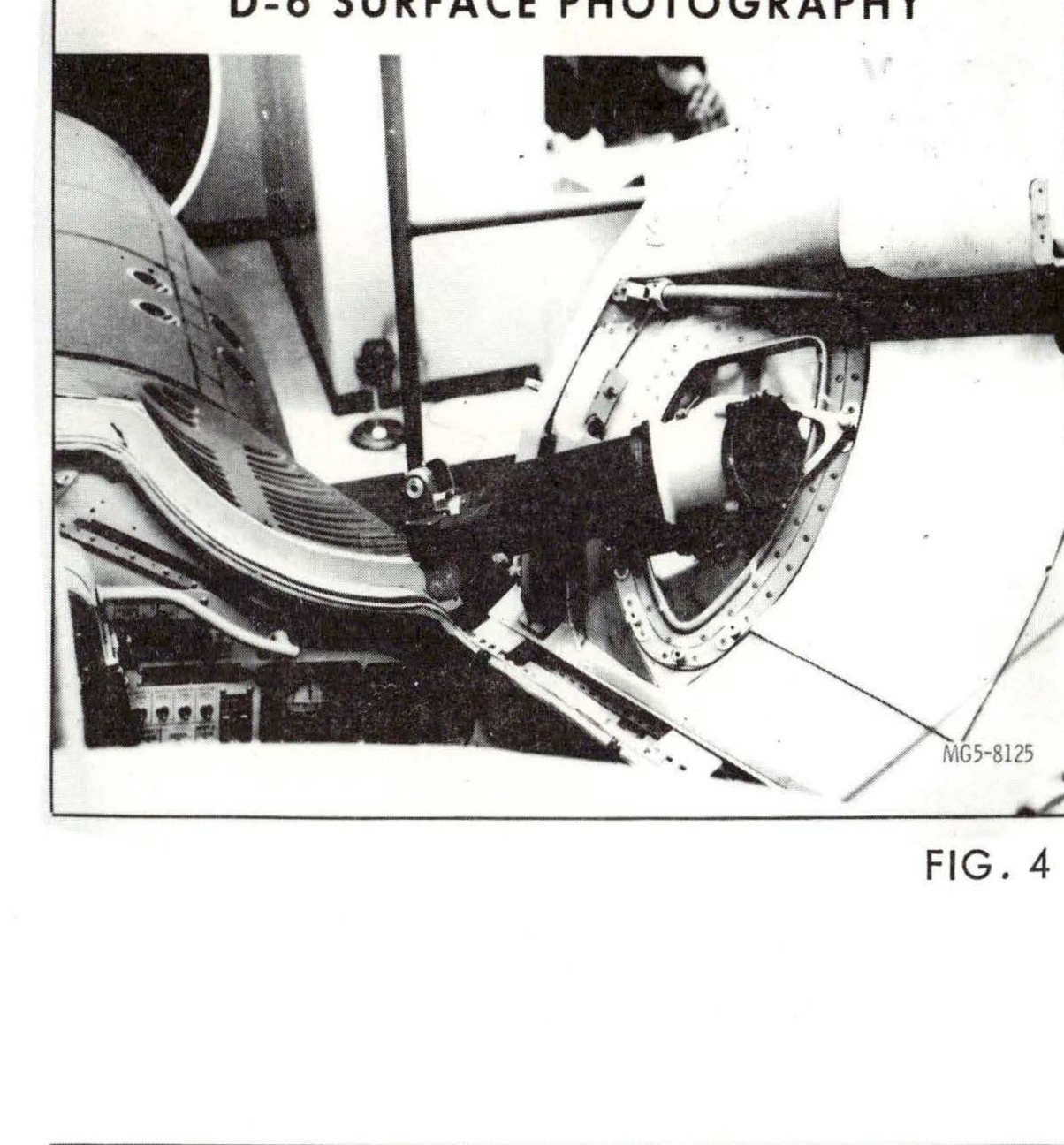
D-6 SURFACE PHOTOGRAPHY - camera mount installed on spacecraft window, labeled FIG. 4, MGS-8125
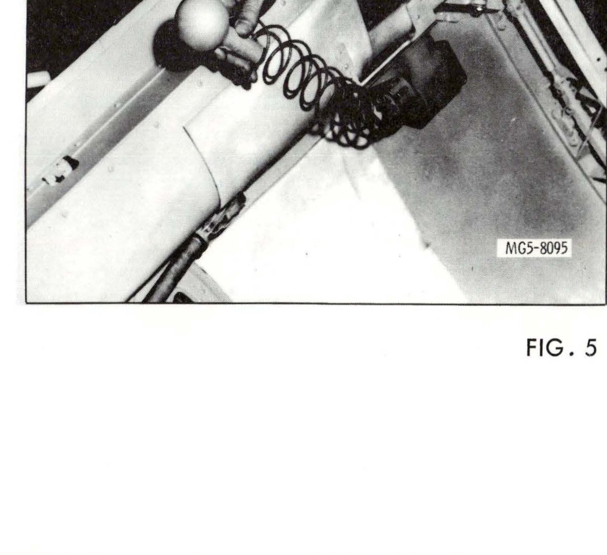
D-8 RADIATION IN SPACECRAFT (PORTABLE UNIT) - radiation detection equipment, labeled FIG. 5, MGS-8095
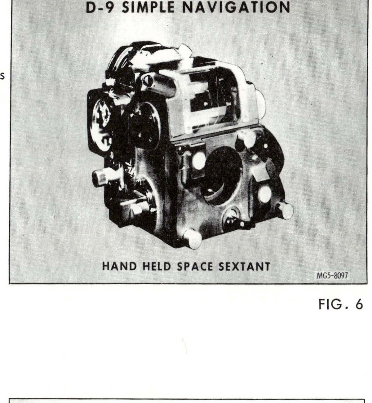
D-9 SIMPLE NAVIGATION - HAND HELD SPACE SEXTANT (FIG. 6)
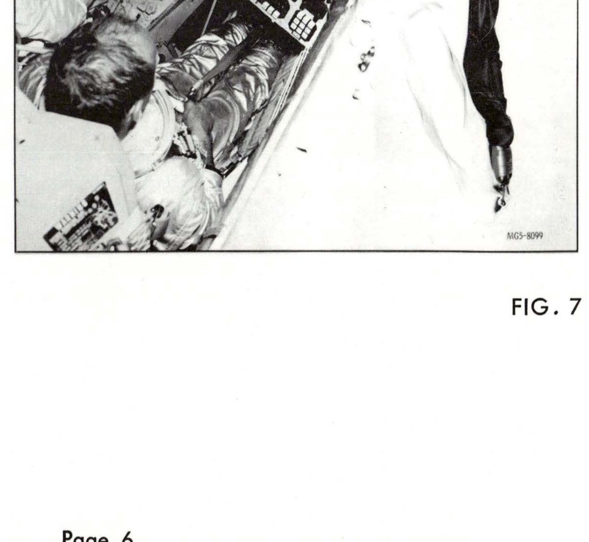
M-3 IN-FLIGHT EXERCISER (FIG. 7)
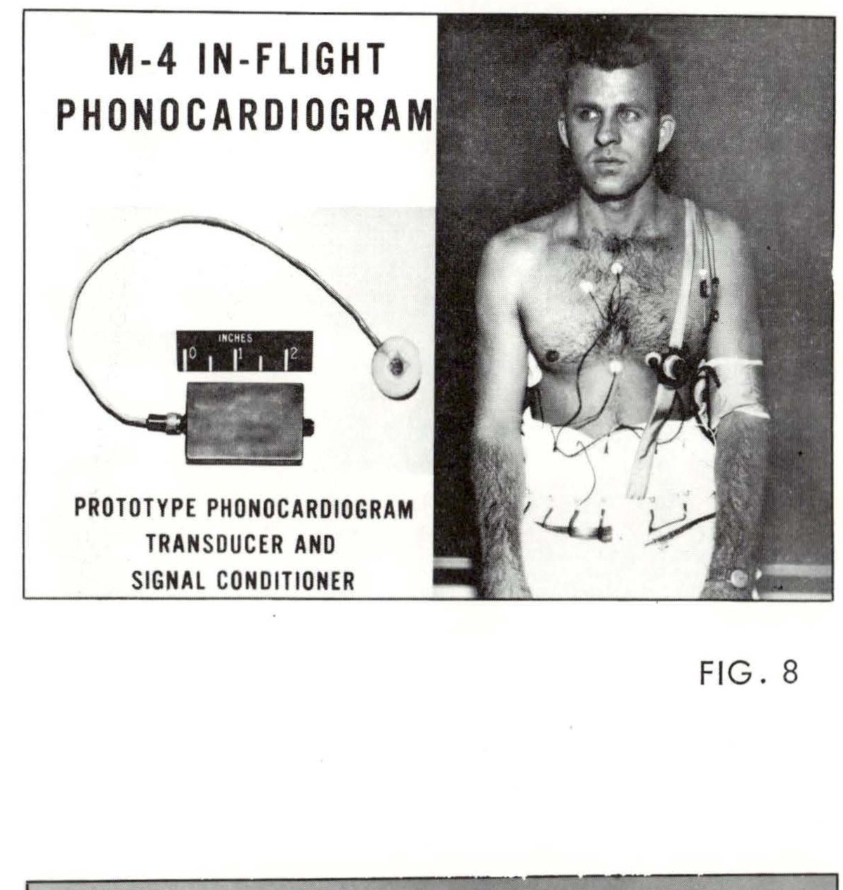
M-4 IN-FLIGHT PHONOCARDIOGRAM - PROTOTYPE PHONOCARDIOGRAM TRANSDUCER AND SIGNAL CONDITIONER with photograph of astronaut wearing device
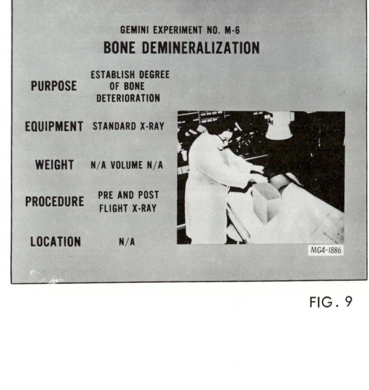
GEMINI EXPERIMENT NO. M-6 BONE DEMINERALIZATION showing purpose, equipment, weight, procedure, and location details with photograph of X-ray procedure
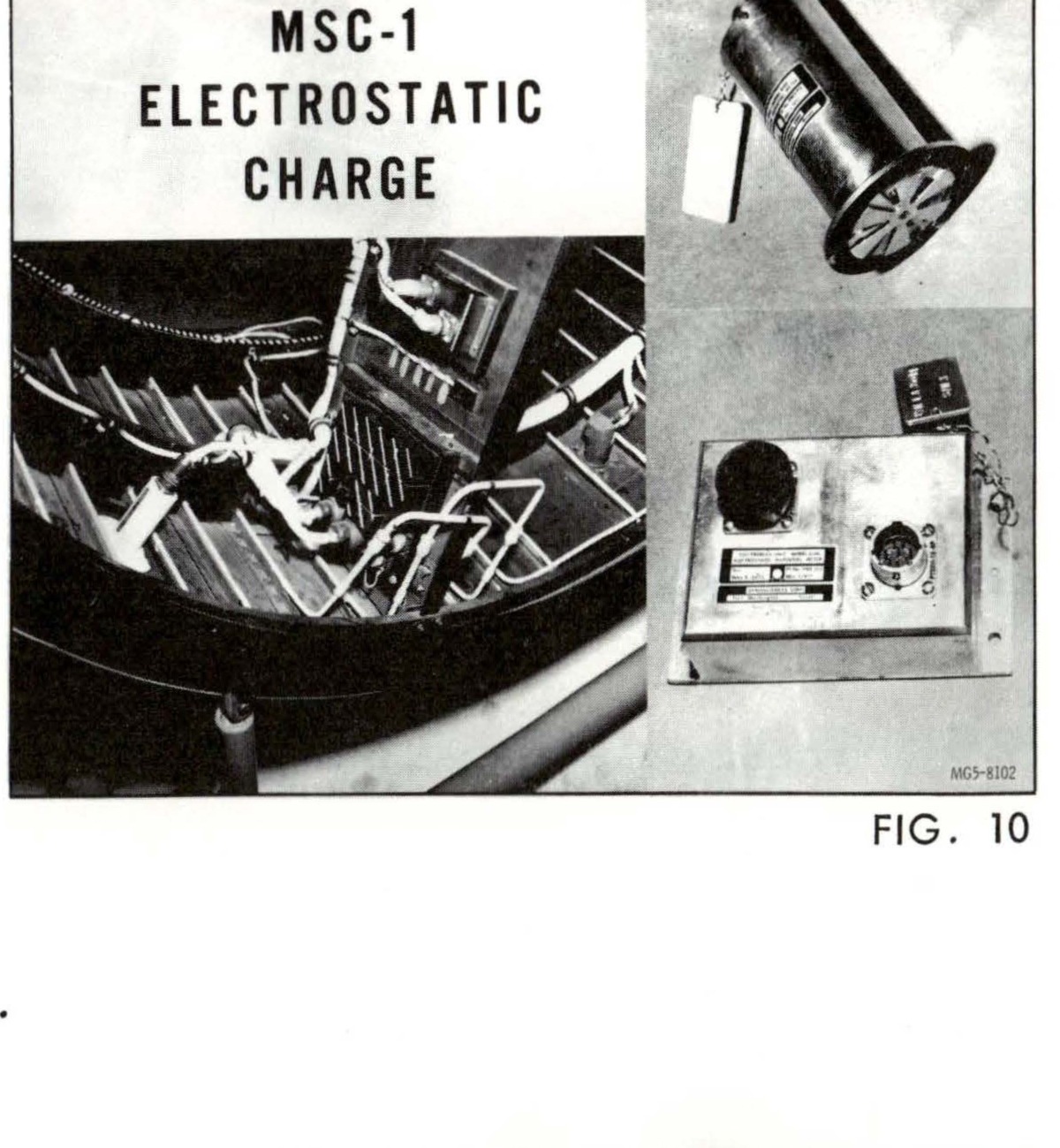
MSC-1 ELECTROSTATIC CHARGE detector installation, FIG. 10
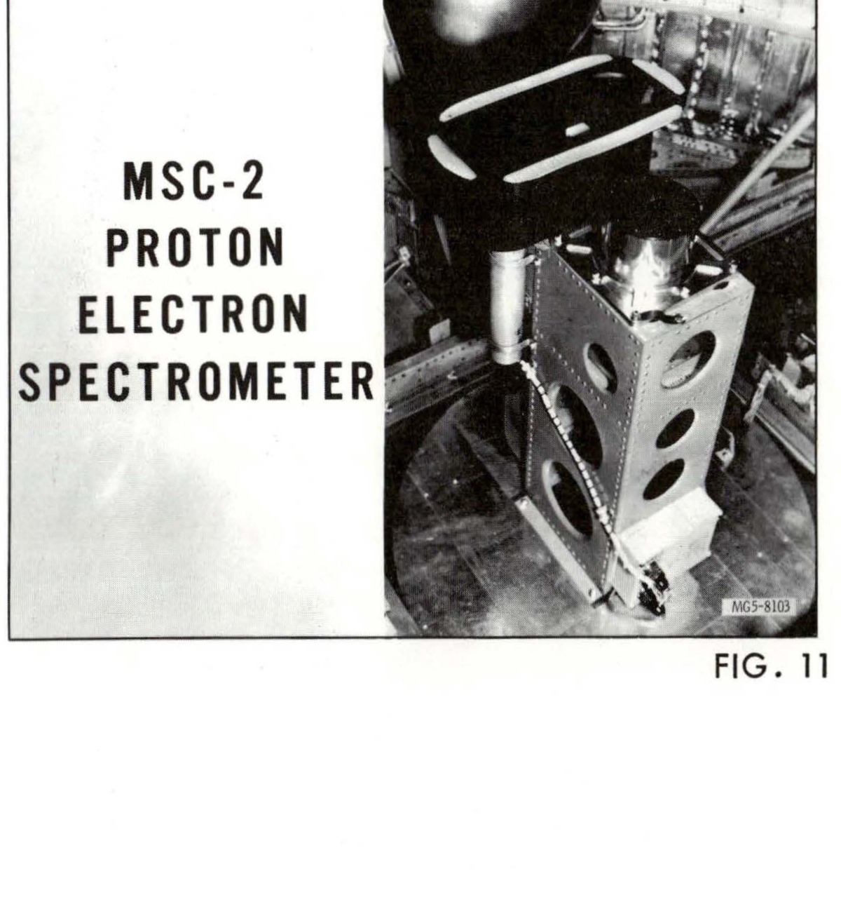
MSC-2 PROTON ELECTRON SPECTROMETER installation, FIG. 11
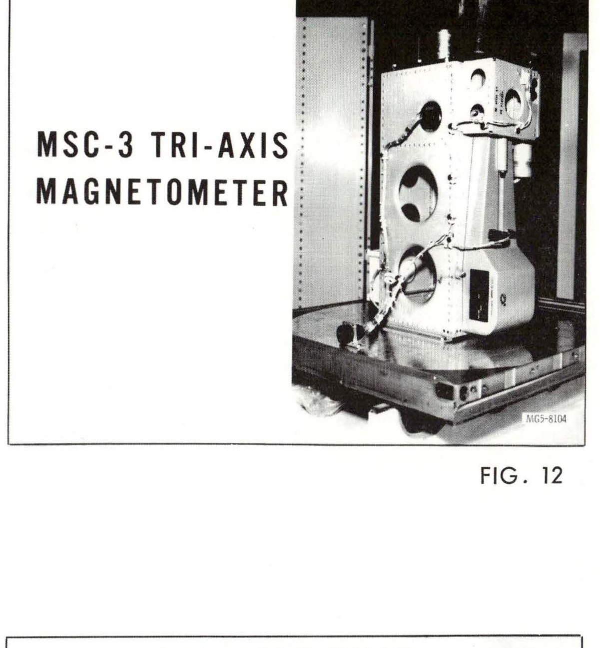
MSC-3 TRI-AXIS MAGNETOMETER - FIG. 12
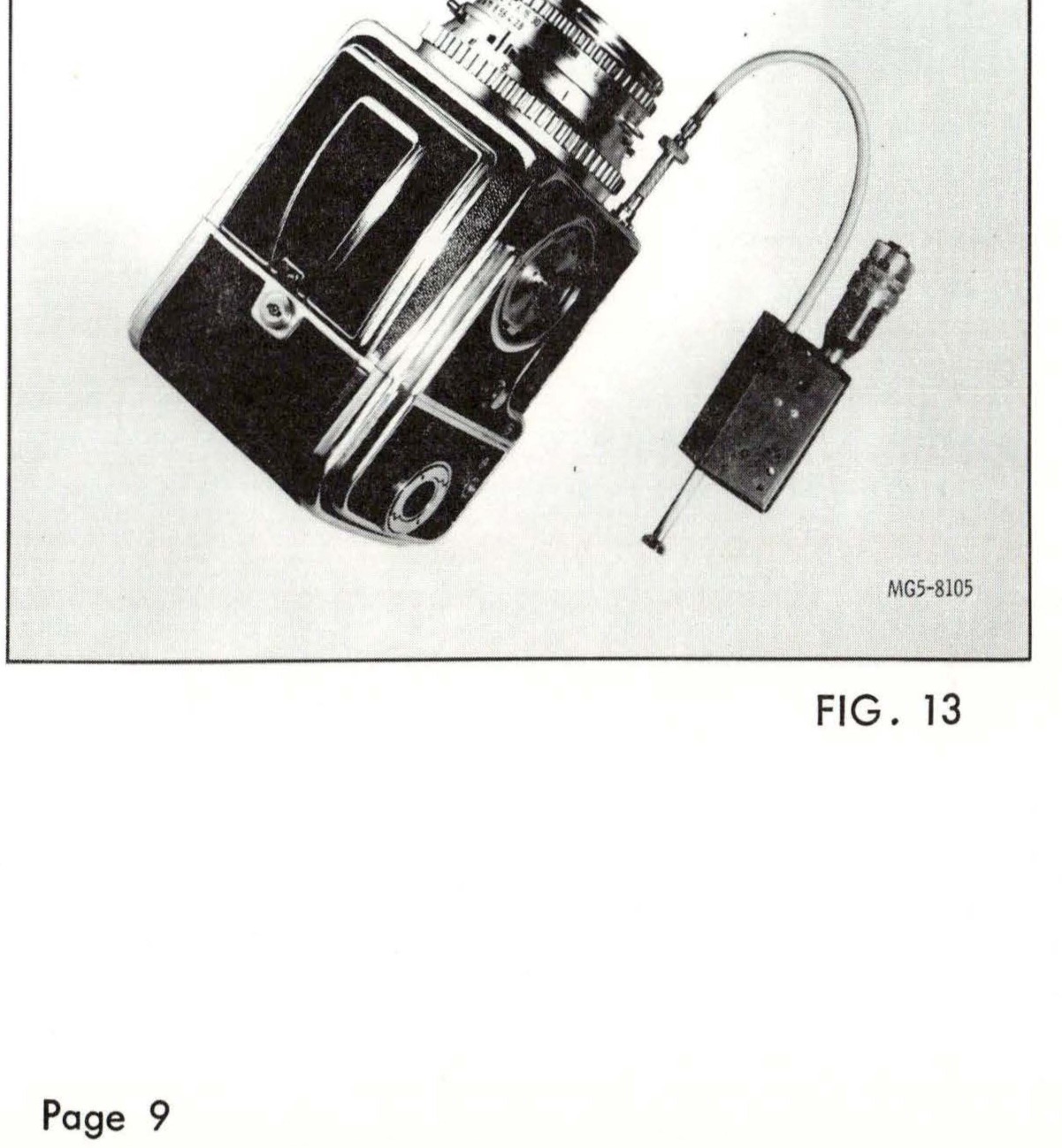
MSC-10 TWO-COLOR EARTH'S LIMB PHOTOS - FIG. 13
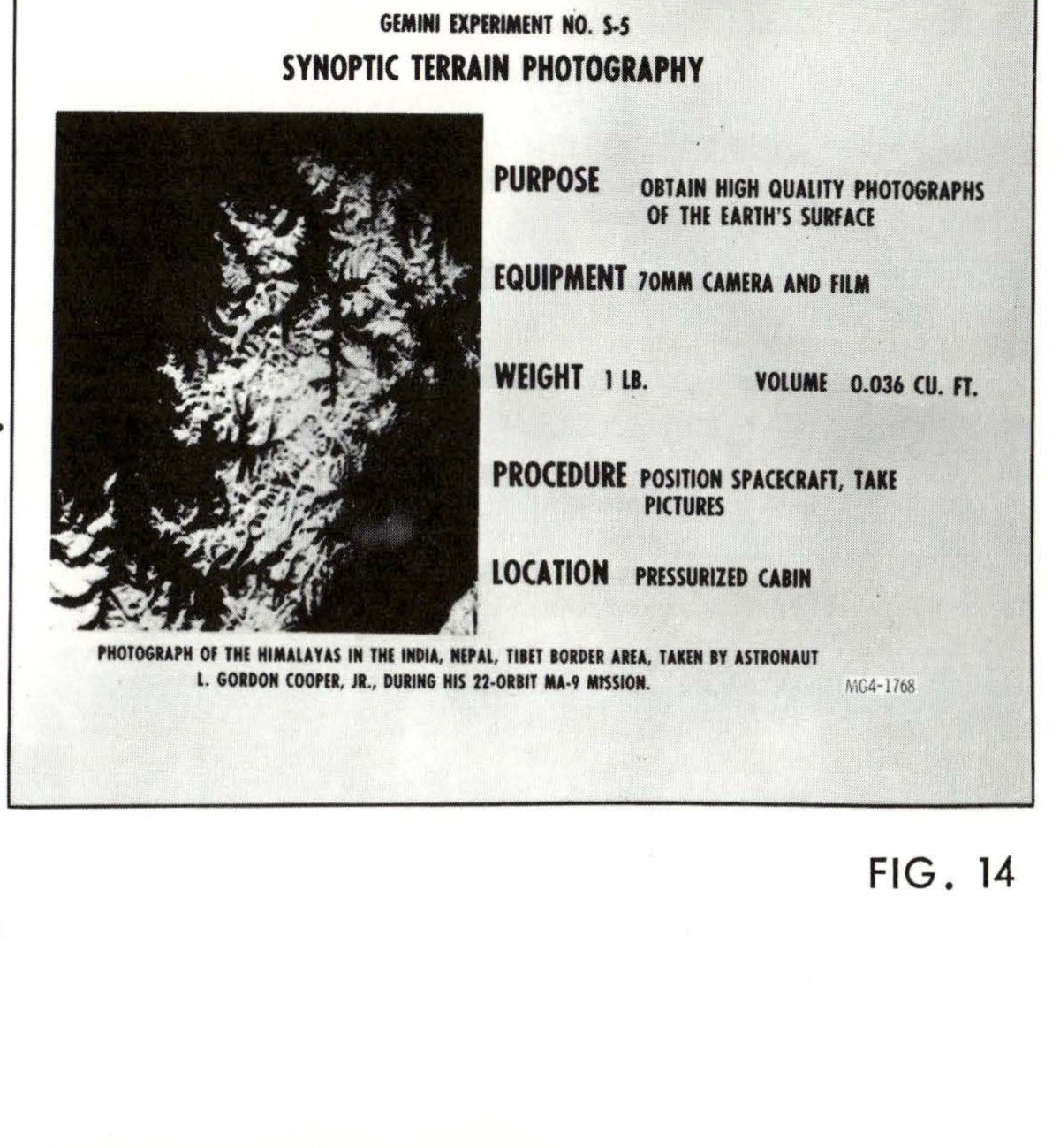
GEMINI EXPERIMENT NO. S-5 SYNOPTIC TERRAIN PHOTOGRAPHY - Photograph of the Himalayas in the India, Nepal, Tibet border area, taken by astronaut L. Gordon Cooper, Jr., during his 22-orbit MA-9 mission. PURPOSE: Obtain high quality photographs of the earth's surface. EQUIPMENT: 70MM camera and film. WEIGHT: 1 lb. VOLUME: 0.036 cu. ft. PROCEDURE: Position spacecraft, take pictures. LOCATION: Pressurized cabin. MSC-1768. FIG. 14
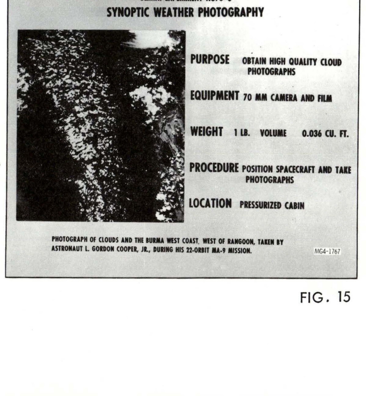
GEMINI EXPERIMENT NO. S-6 SYNOPTIC WEATHER PHOTOGRAPHY - Photograph of clouds and the Bimini West Coast, west of Bangkok, taken by astronaut L. Gordon Cooper, Jr., during his 22-orbit MA-9 mission. PURPOSE: Obtain high quality cloud photographs. EQUIPMENT: 70 MM camera and film. WEIGHT: 1 lb. VOLUME: 0.036 cu. ft. PROCEDURE: Position spacecraft and take photographs. LOCATION: Pressurized cabin. MSC-1767. FIG. 15
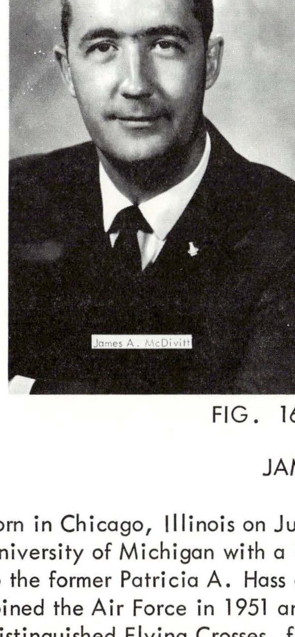
James A. McDivitt
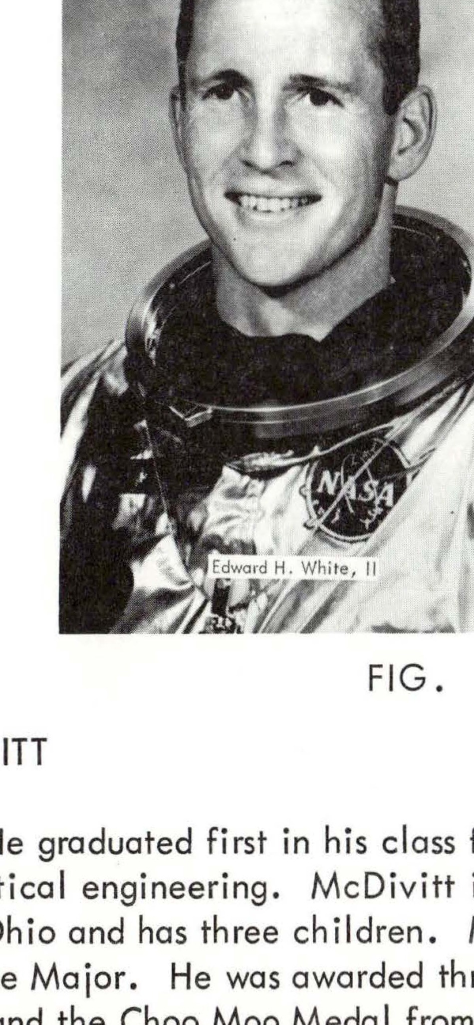
Edward H. White, II
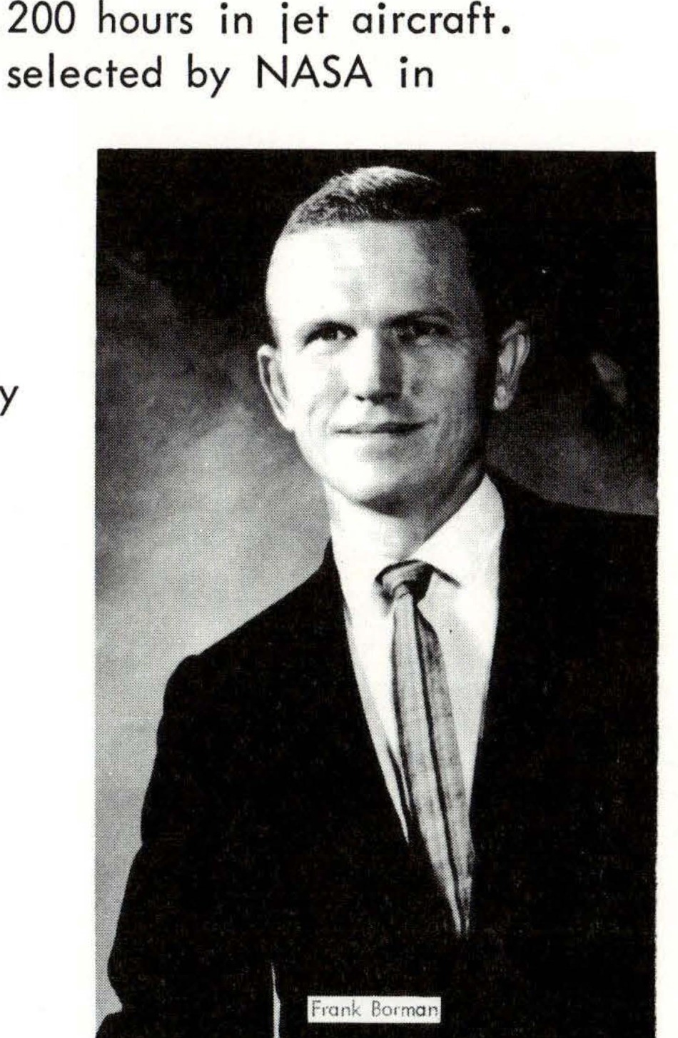
FIG. 18 - Portrait photograph of Frank Borman
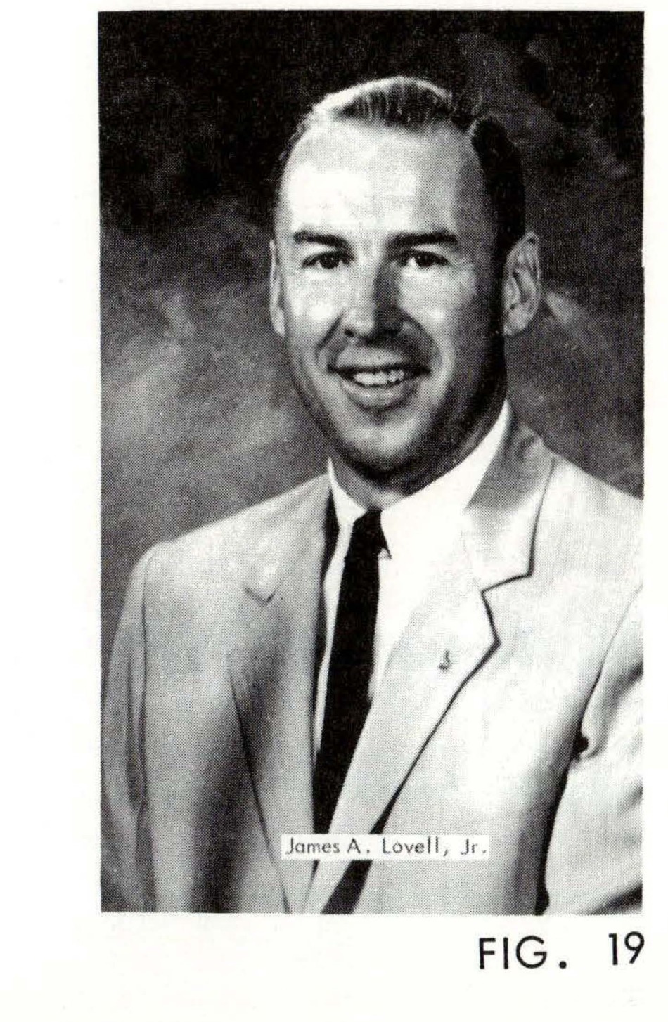
FIG. 19 - Portrait photograph of James A. Lovell, Jr.
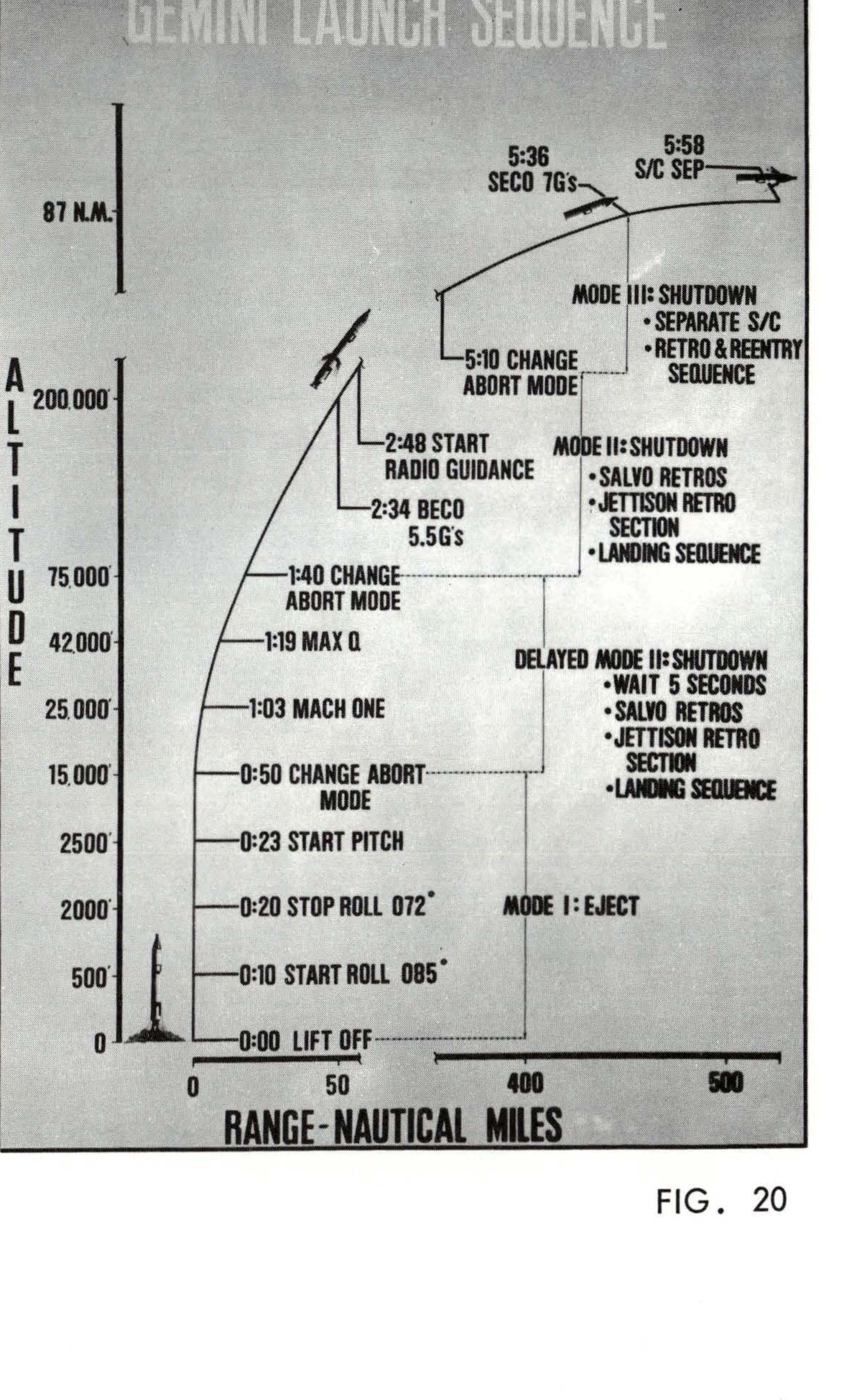
GEMINI LAUNCH SEQUENCE - Figure 20 showing altitude vs range trajectory with mission events
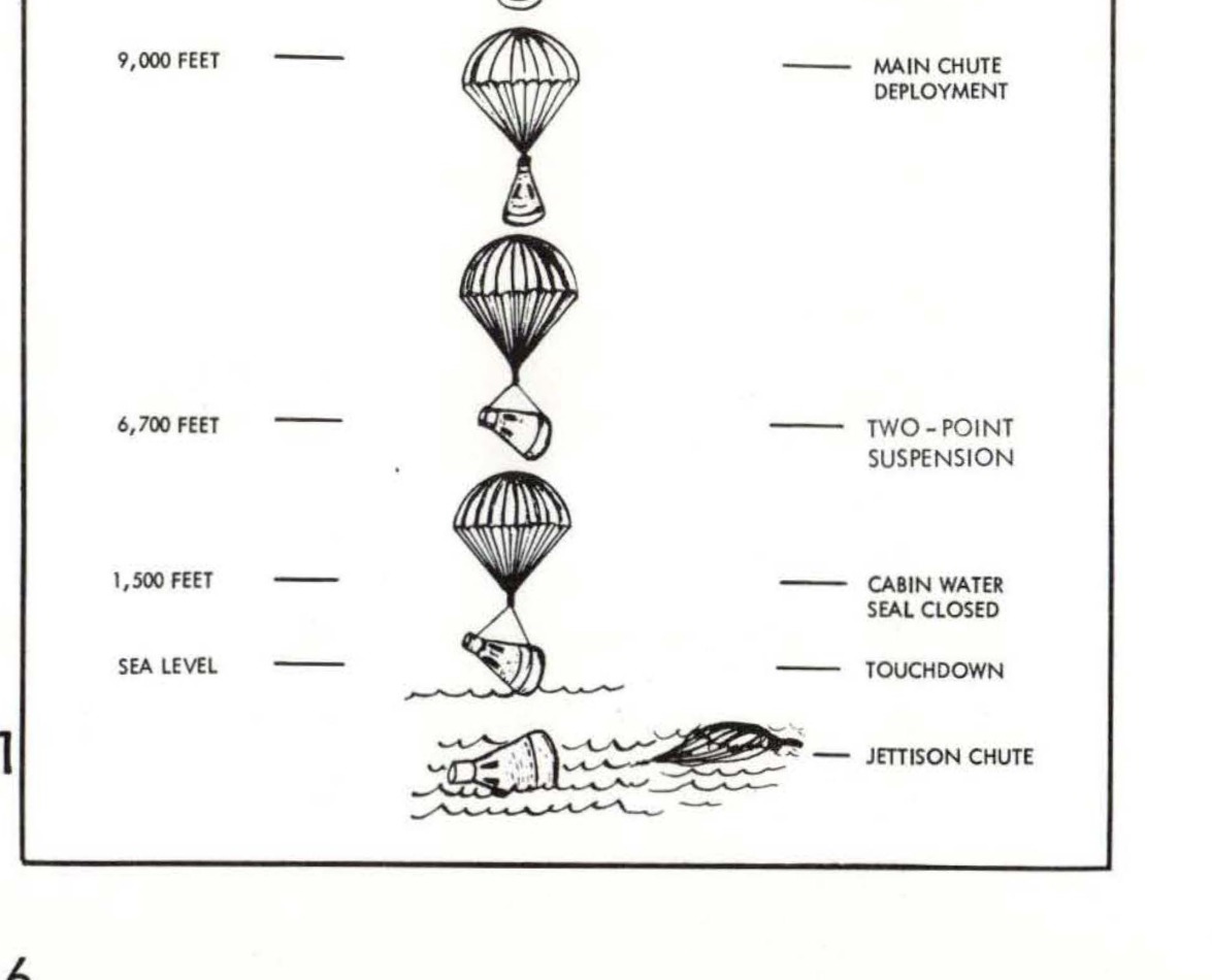
GEMINI PARACHUTE LANDING SEQUENCE showing descent stages from 30,000 feet to touchdown with labeled parachute deployments
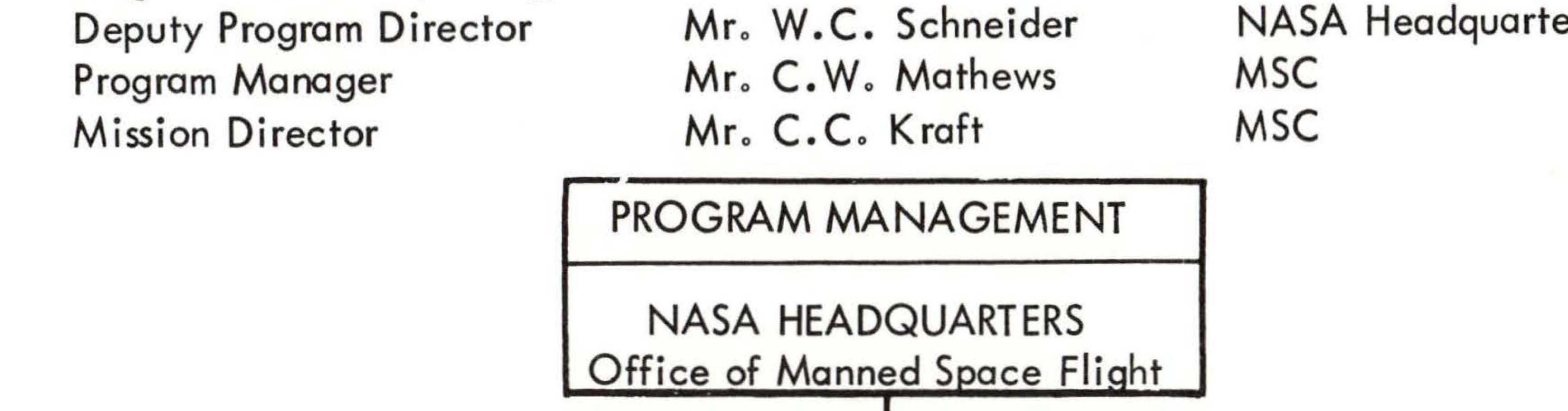
Program and Project Management organizational structure showing NASA Headquarters and Manned Spacecraft Center
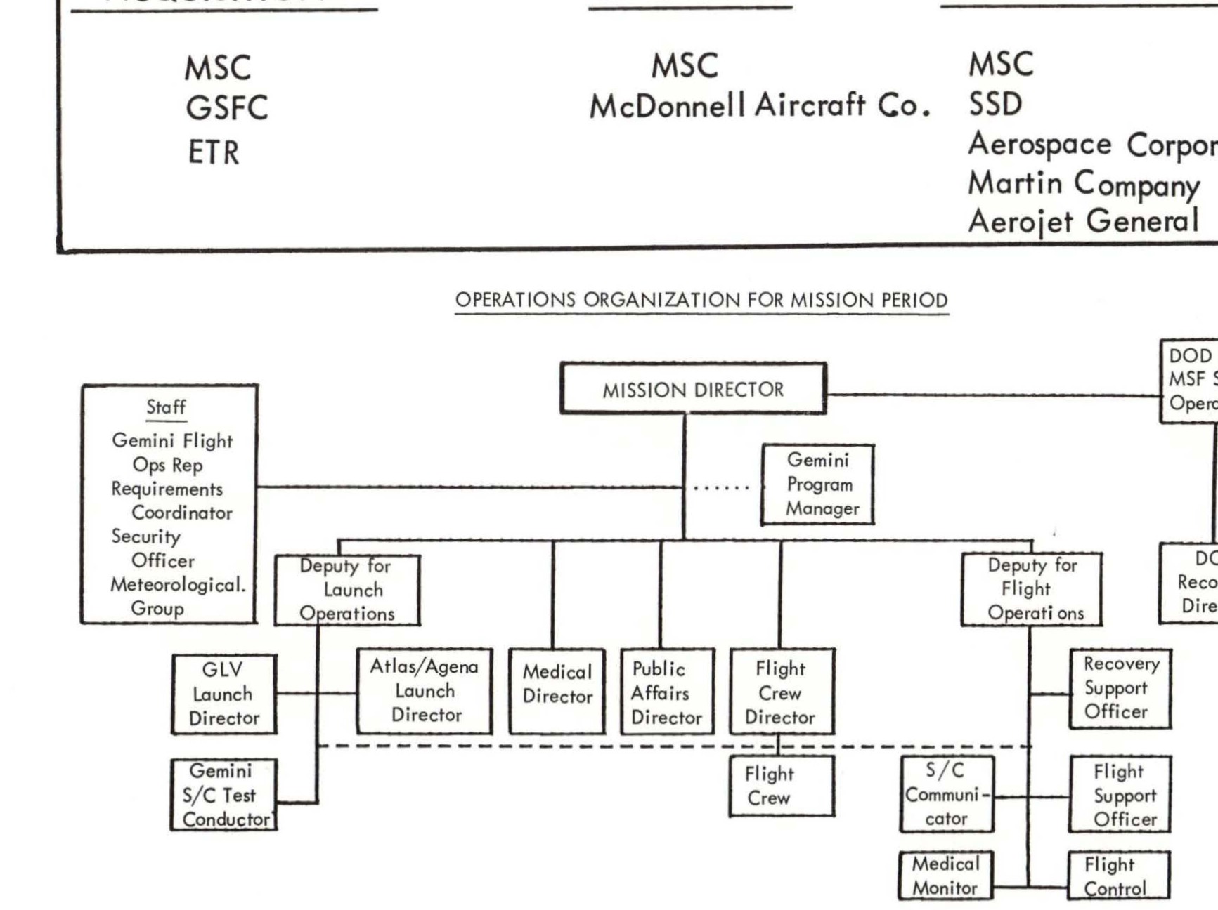
Operations organization chart for mission period showing Mission Director and supporting staff hierarchy
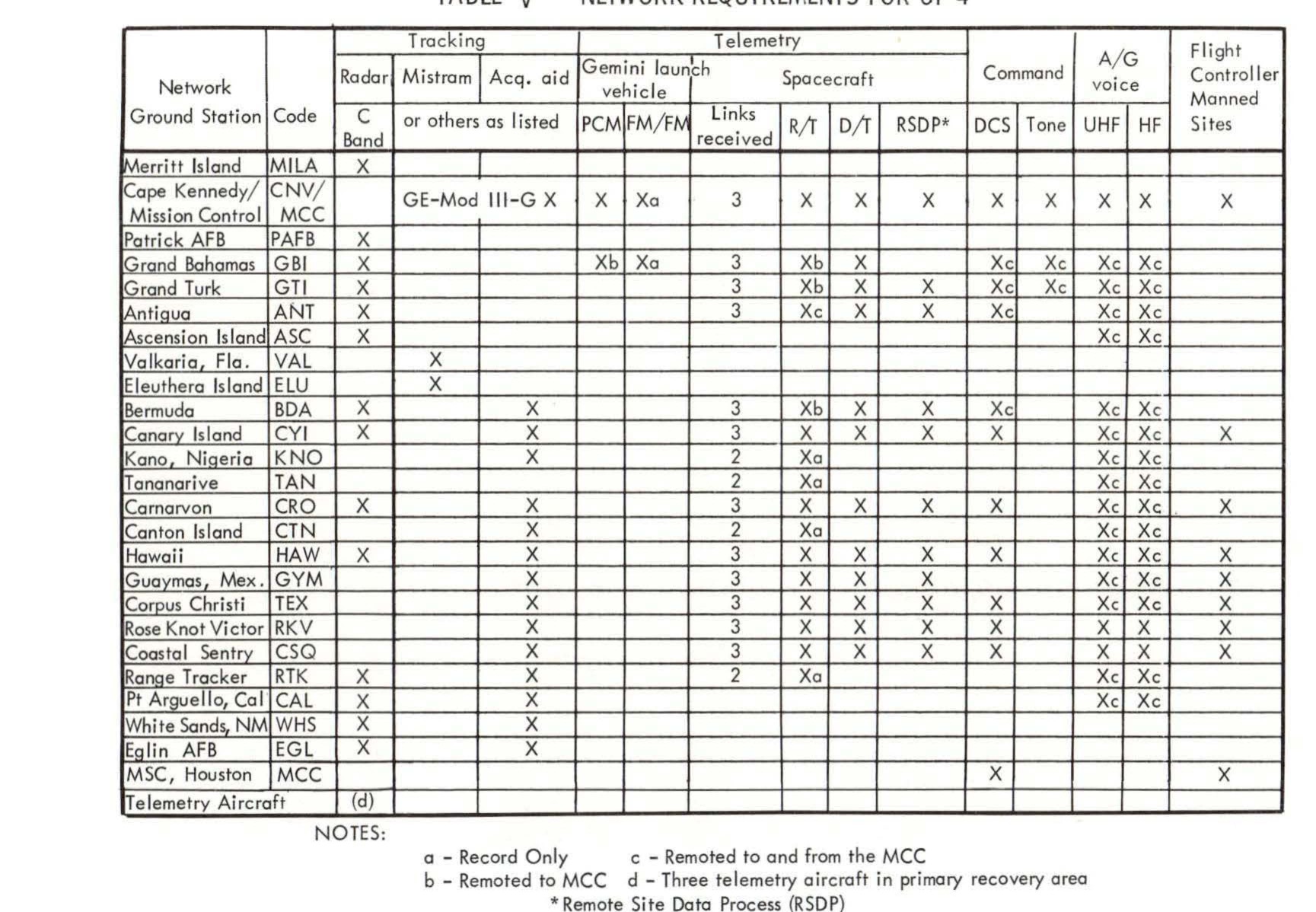
TABLE V - NETWORK REQUIREMENTS FOR GT-4 showing tracking network ground stations with radar, telemetry, and command capabilities
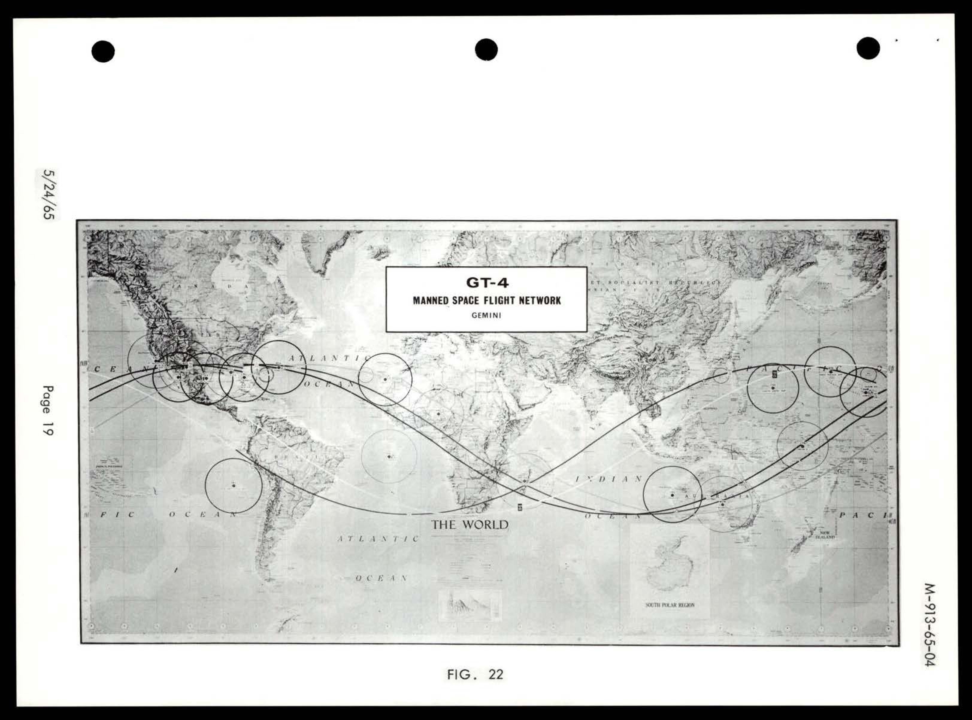
World map showing GT-4 Manned Space Flight Network (Gemini) with tracking stations and orbital paths marked by circles and lines across continents and oceans
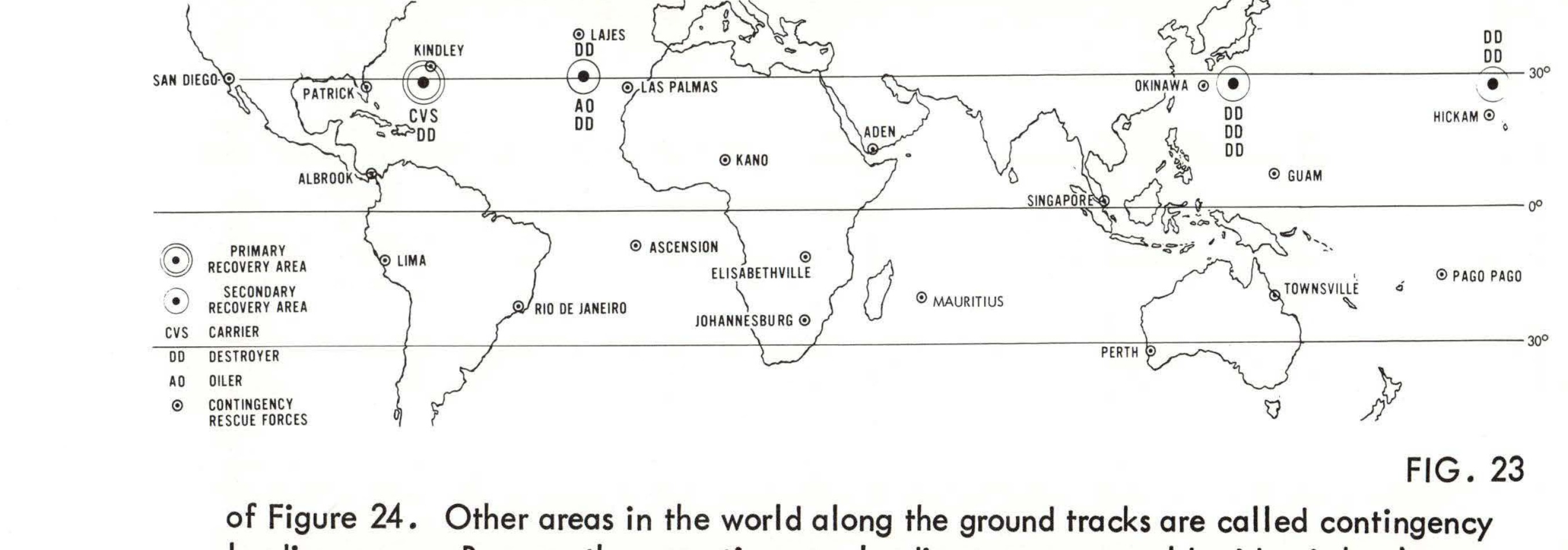
World map showing GT-4 primary and secondary landing zones with recovery ship support and contingency rescue forces locations
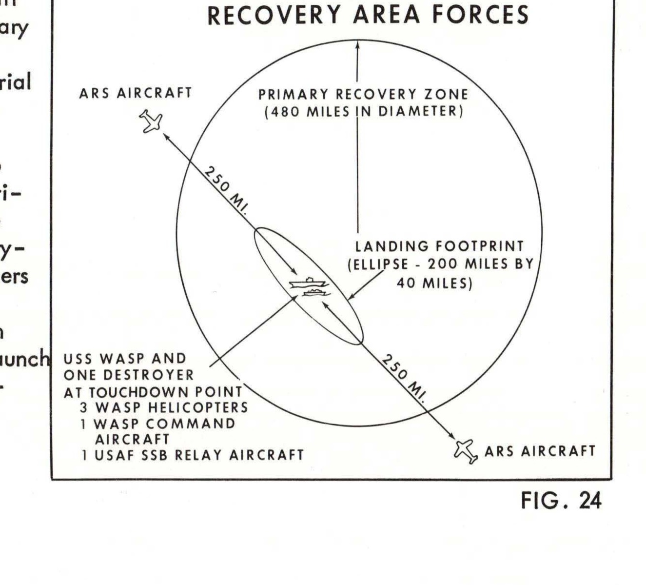
Recovery Area Forces diagram showing primary recovery zone, landing footprint, and deployment of USS WASP, destroyer, helicopters, and aircraft
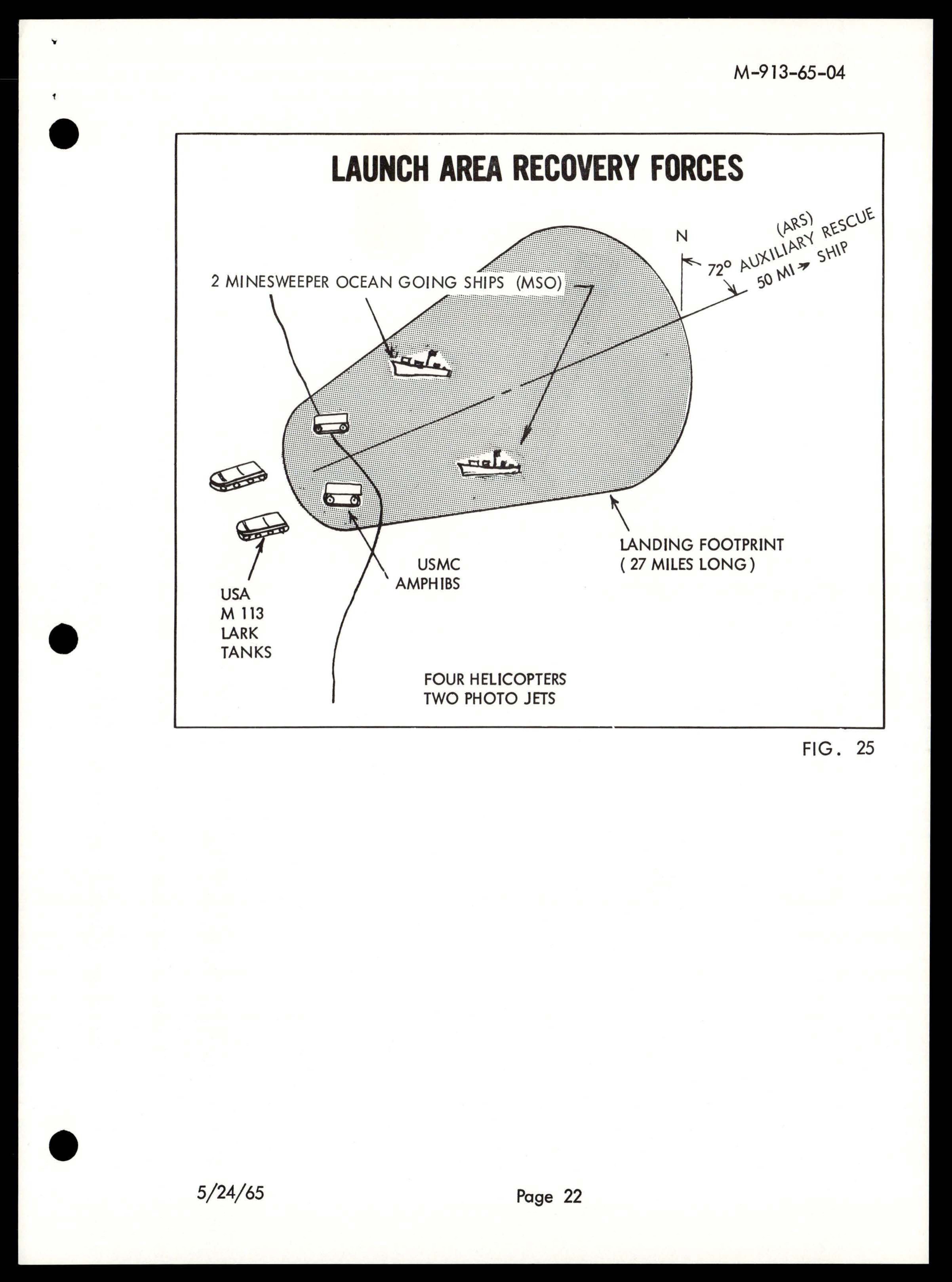
Diagram showing launch area recovery forces deployment including minesweeper ships, USMC amphibs, USA M 113 LARK tanks, helicopters, photo jets, and auxiliary rescue ship positioned around a 27-mile landing footprint

Timeline diagram showing boxes labeled GYMEX, CNT, ANT, ASC, PRE, TAN, N/GHT, CDO, HAW

Newspaper clipping from The Washington Post, August 26, 1965, reporting on Gemini 5 spacecraft power issues and mission progress
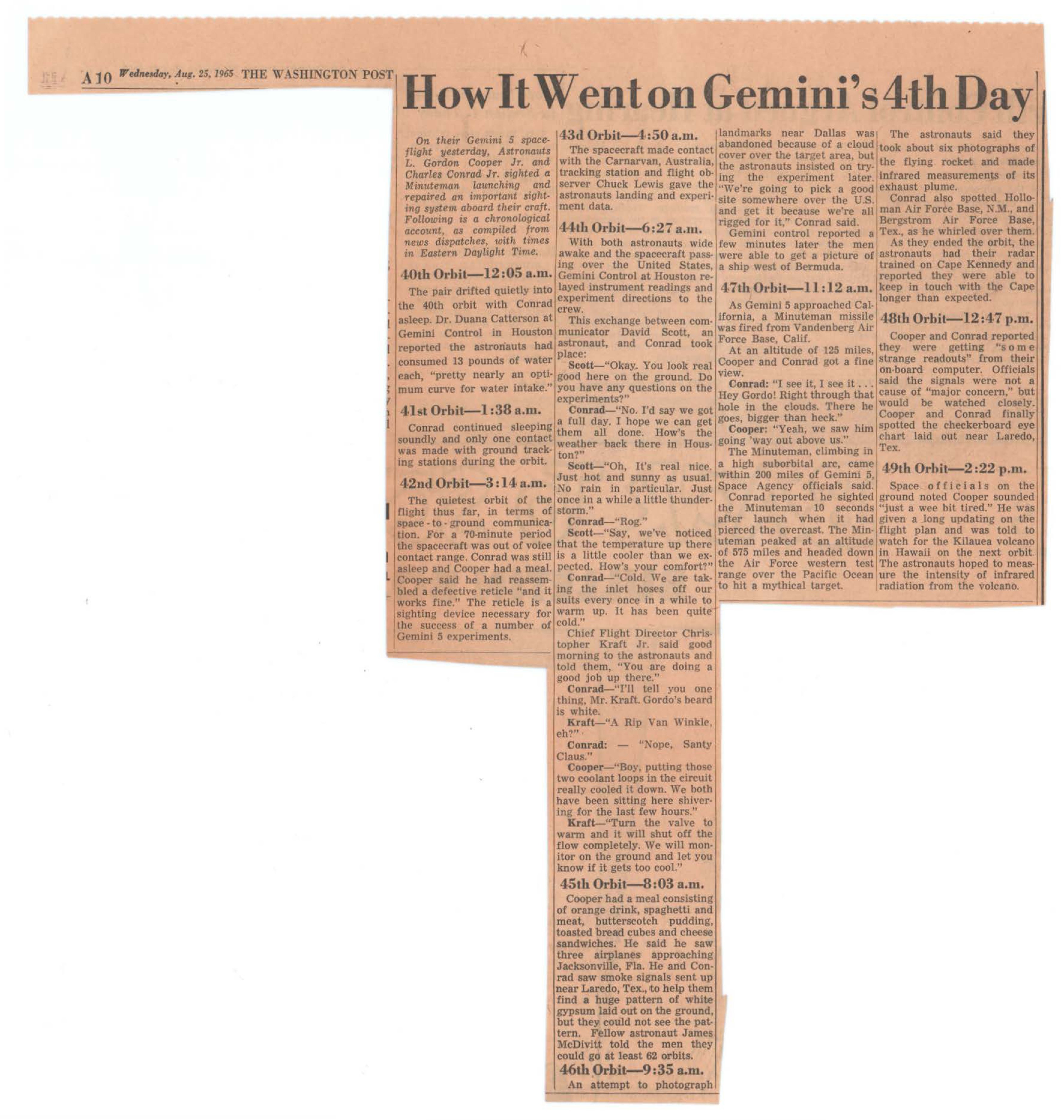
Newspaper clipping from The Washington Post, August 25, 1965, describing chronological events of Gemini 5's fourth day in orbit
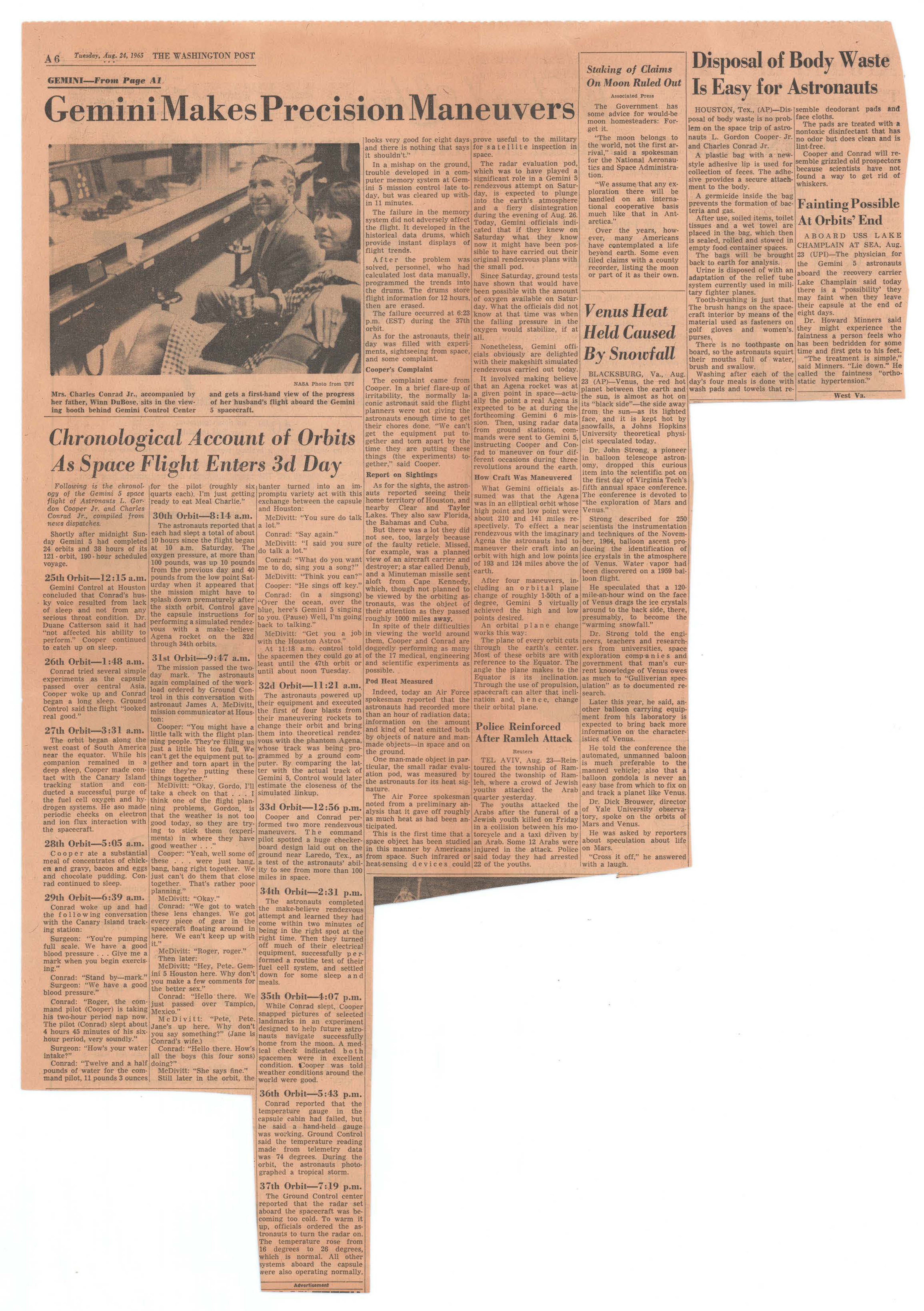
NASA Photo from UPI - Mrs. Charles Conrad Jr. accompanied by her father, Hans Bohlen, sits in the tracking station at Cape Kennedy and gets a firsthand view of the progress of her husband's flight aboard the Gemini spacecraft.
Hand-drawn rectangular box with circular shape inside
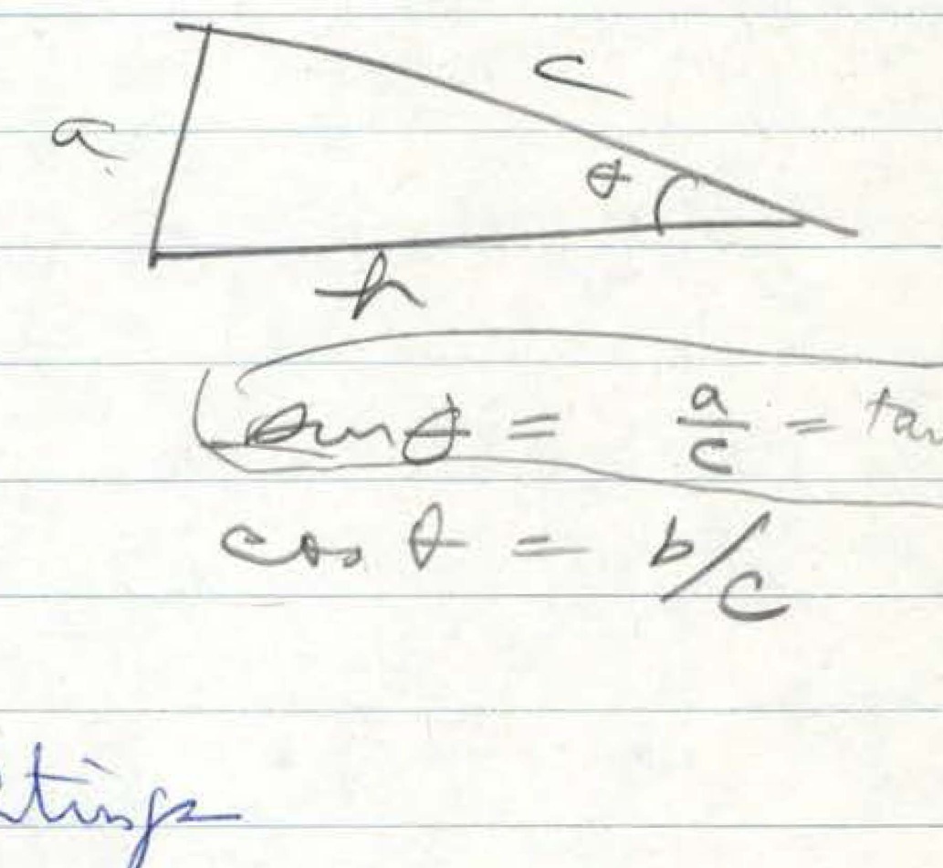
Triangle diagram with mathematical notations including sin d = tan t, sin g + cos g = 1, and cos b = b/c
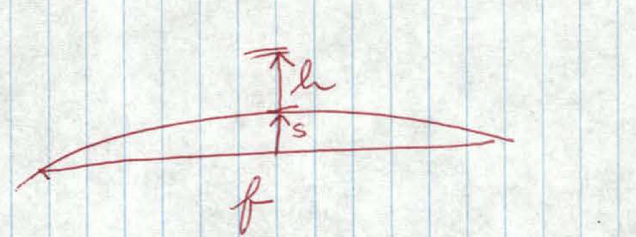
Hand-drawn sketch showing curved object with annotations 'Ta', 's', and 'f'
NASA seal/logo in upper left corner
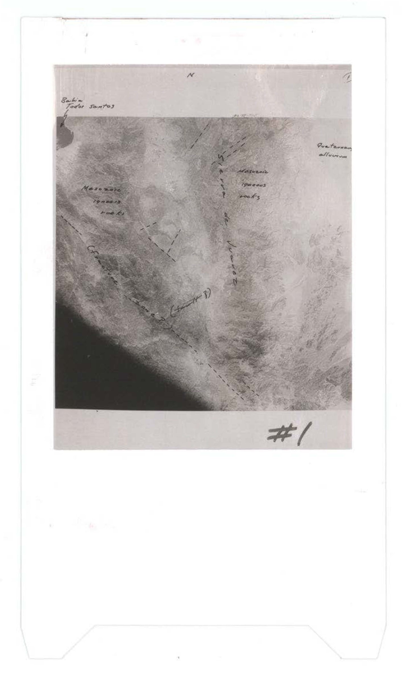
Aerial or satellite photograph showing cloud formations with handwritten annotations indicating broken field sources, prestorm altocumulus, and mesoscale updraft/downdraft complexes, marked as #1
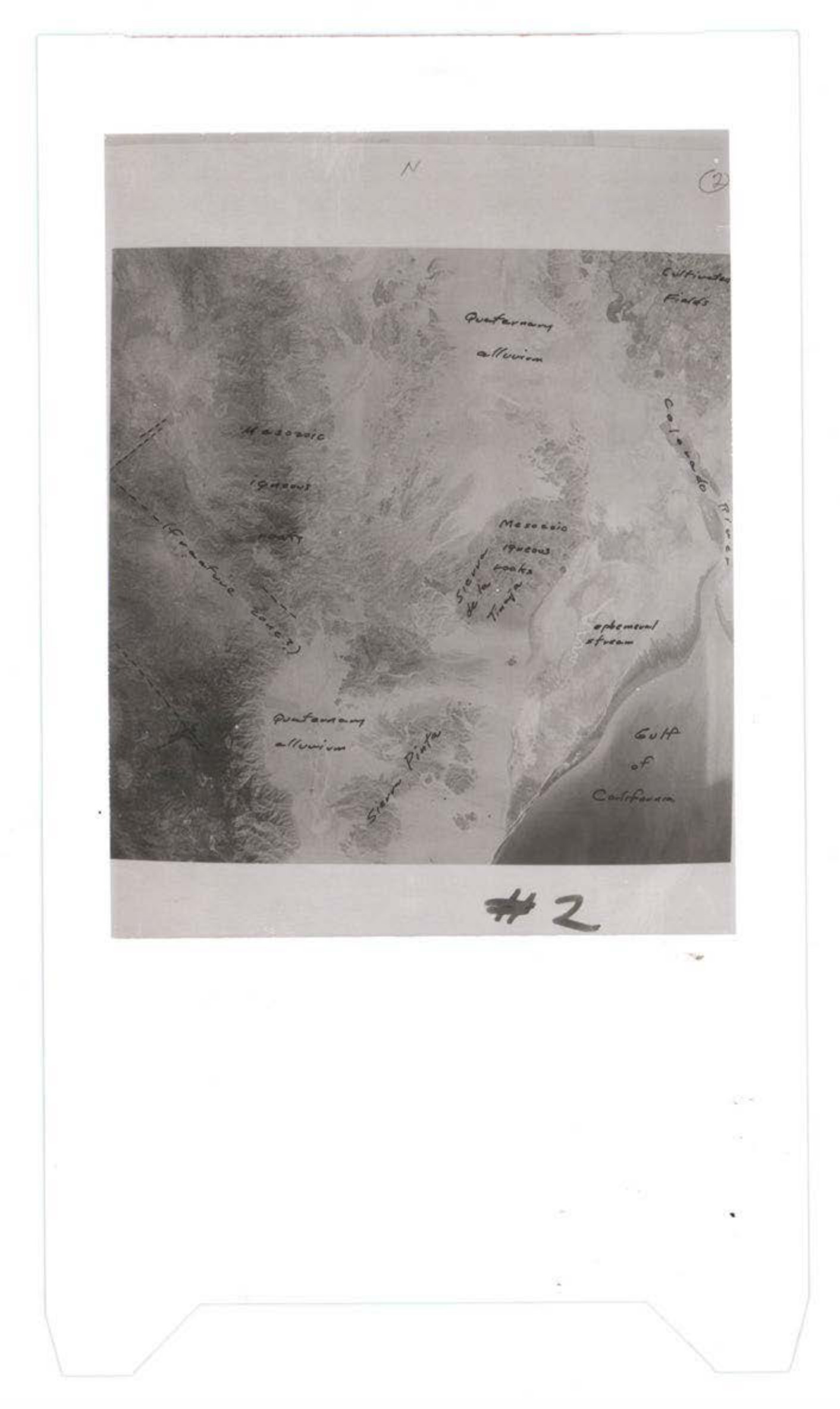
Geological map showing Quaternary alluvium, Mesozoic Tertiary formations, and Gulf of California region with north arrow indicator
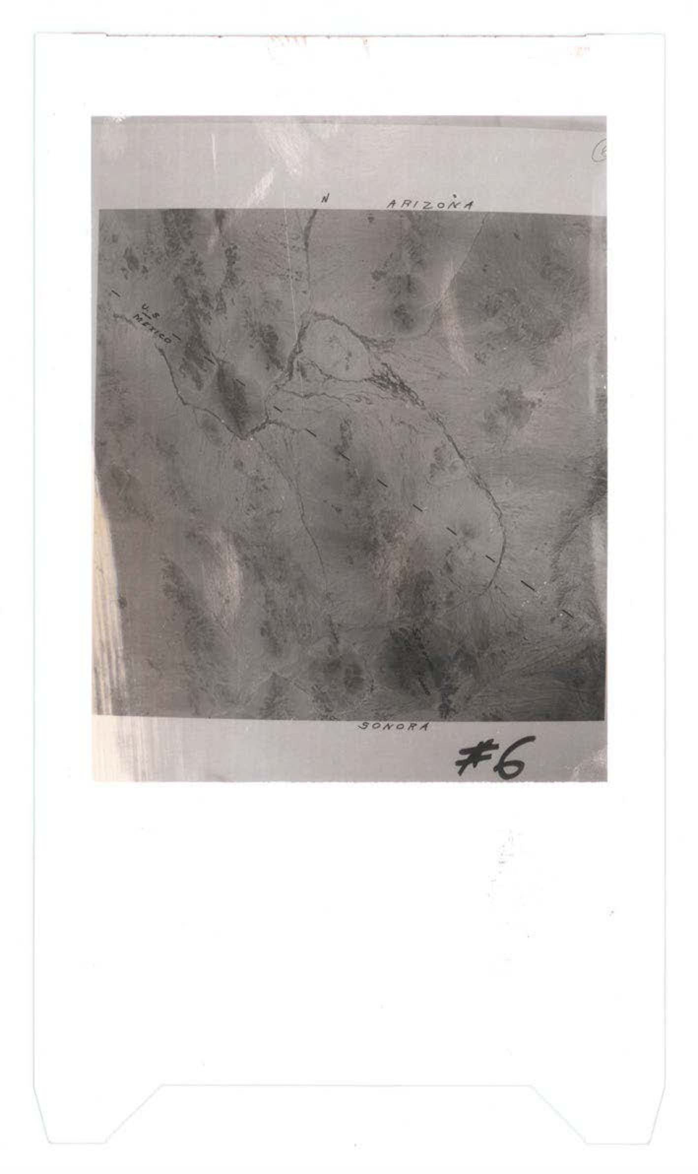
Aerial or topographic map showing border region between Arizona and Sonora, Mexico, with dashed boundary line marked
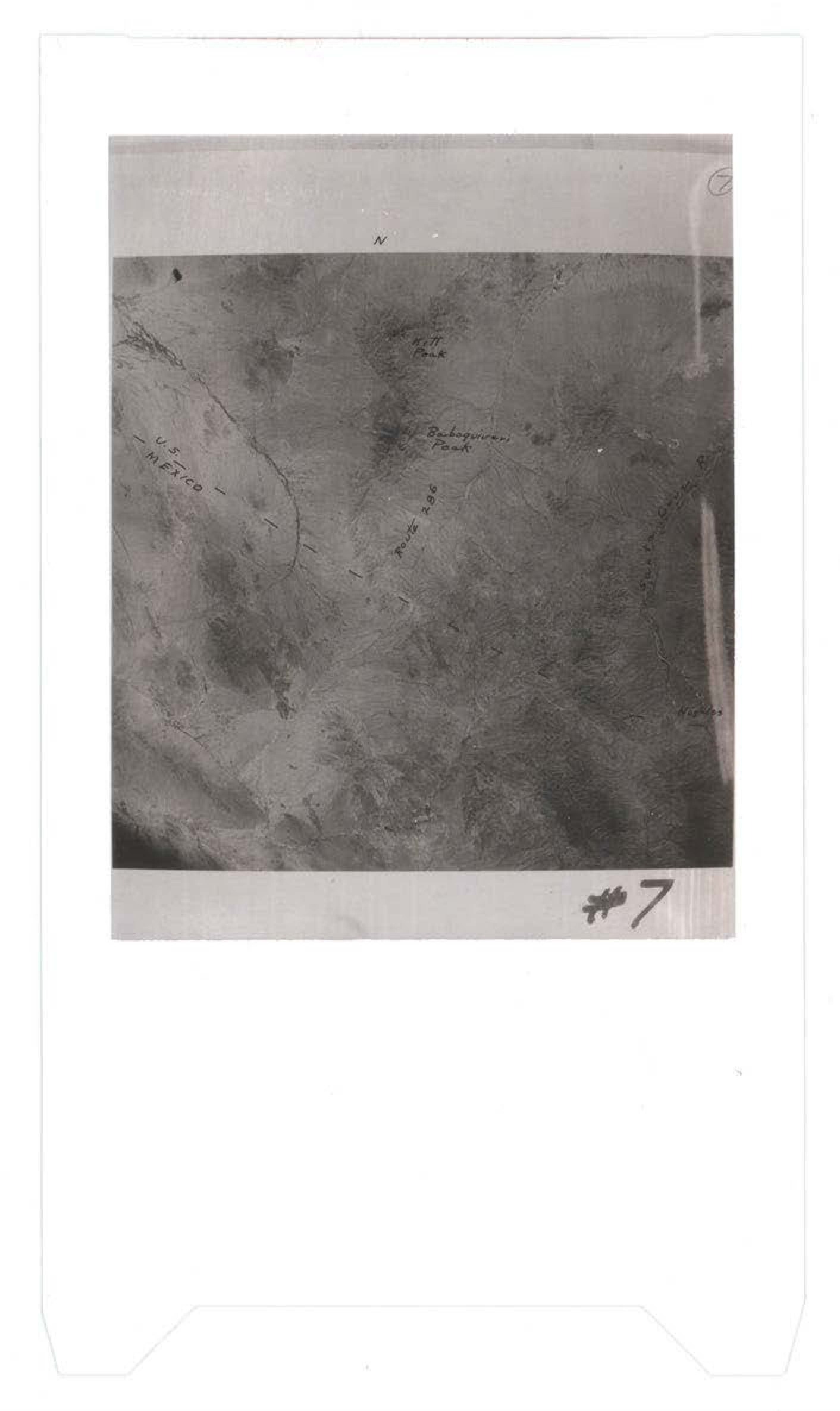
Aerial photograph showing terrain with handwritten annotations indicating Mexico border and Boquequas Peak, marked as #7
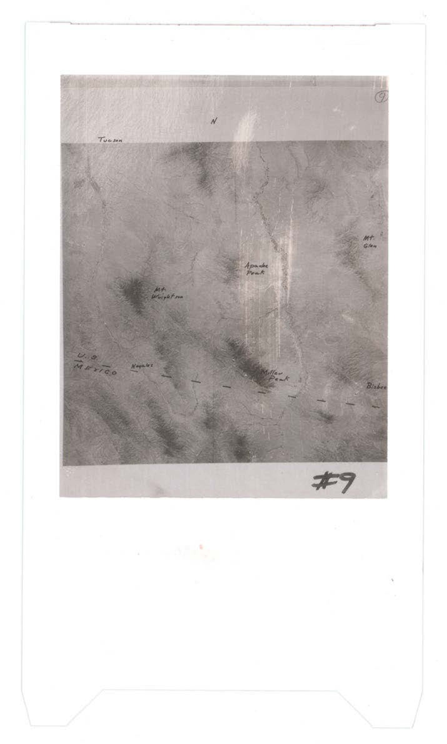
Aerial or topographic map showing terrain features with handwritten labels including Tucson, Apache Peak, Mt. Lemmon, Mt. Gibbs, Lembert, and Highway 89 near Bridgeport, marked as #9
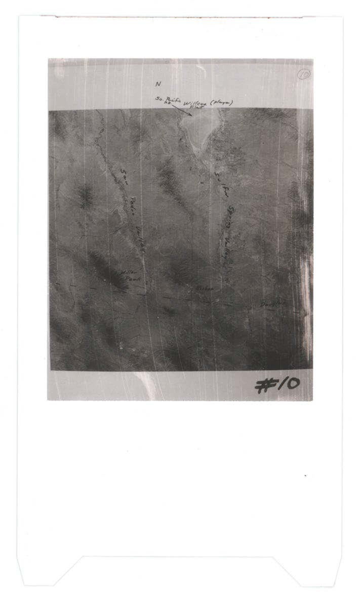
Aerial photograph with handwritten annotations showing terrain features and directional marker N
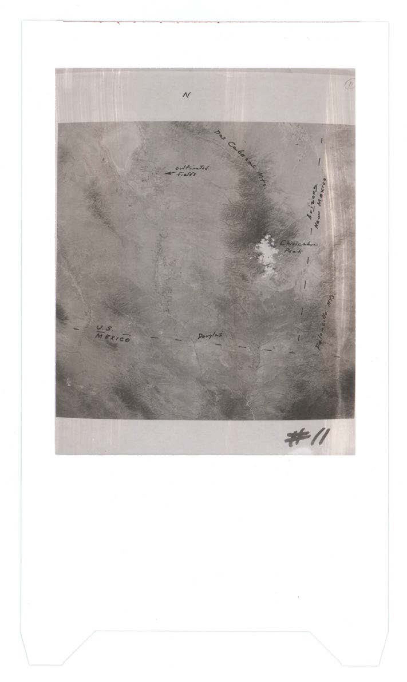
Aerial photograph showing terrain with handwritten annotations including directional marker N, continental trader, U.S. RESTRICTED, Douglas, and numbered #11
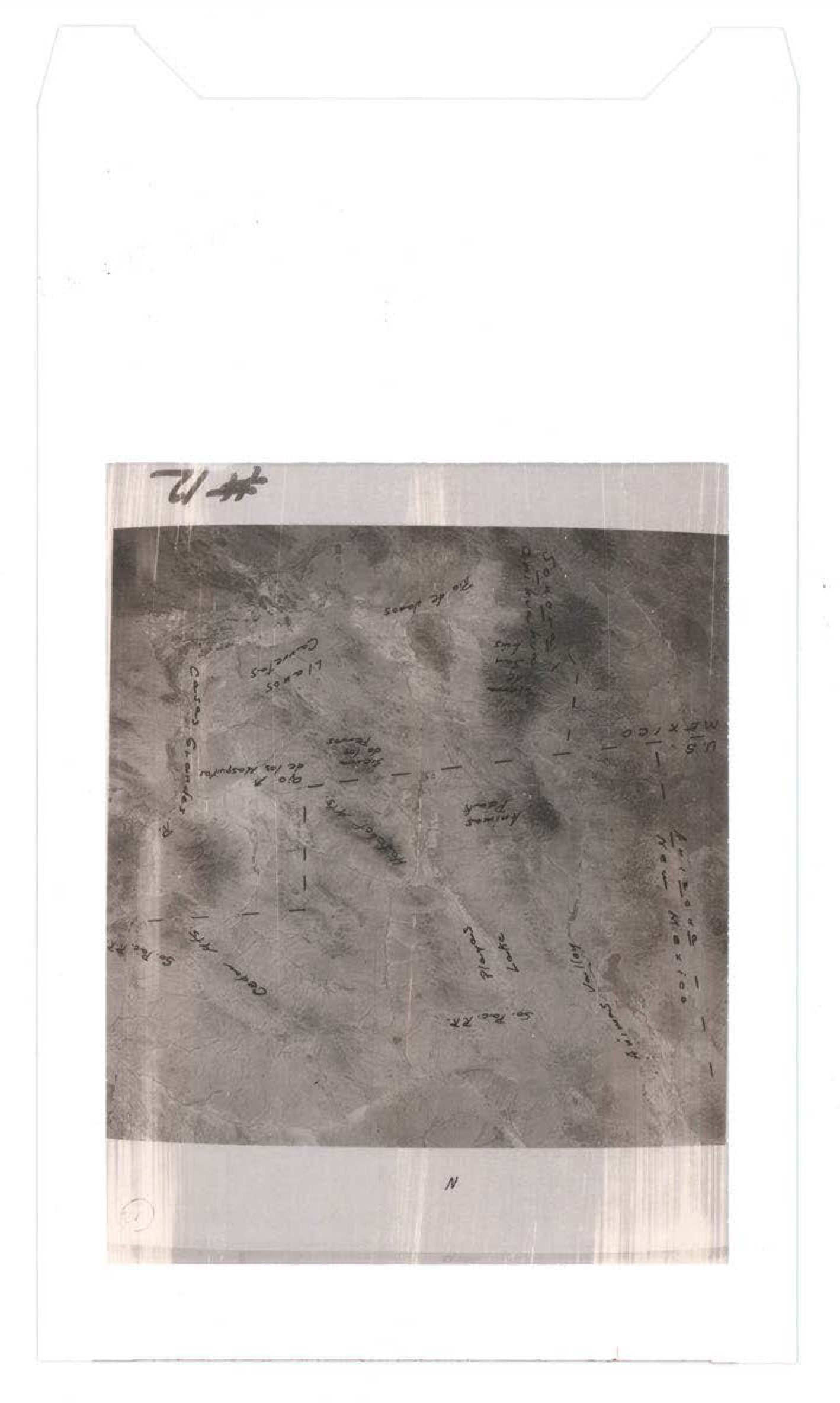
Heavily degraded or damaged photograph with handwritten annotations overlaid; image quality poor with significant deterioration making details illegible
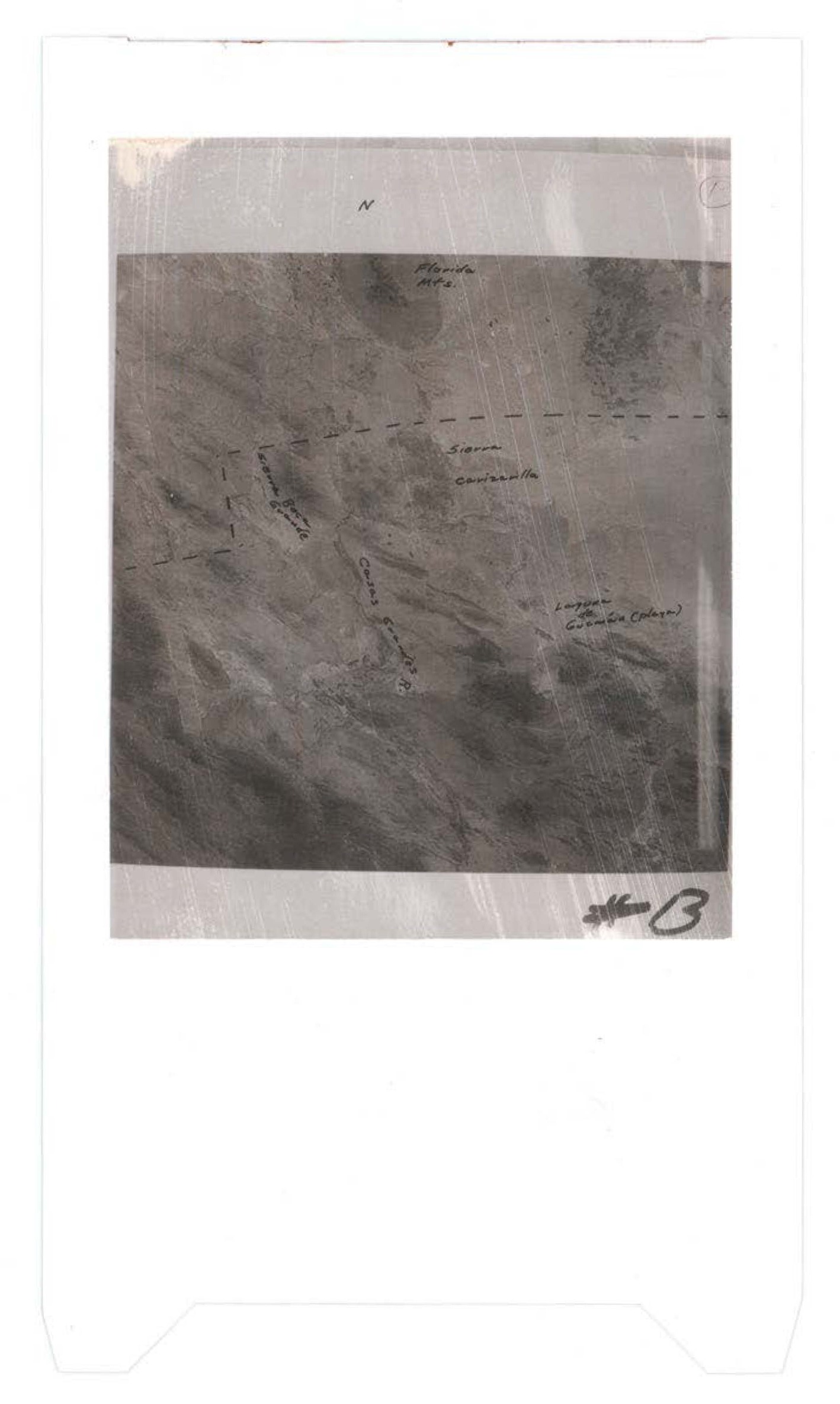
Aerial photograph with handwritten annotations indicating Florida location, storm contrails, and measurements
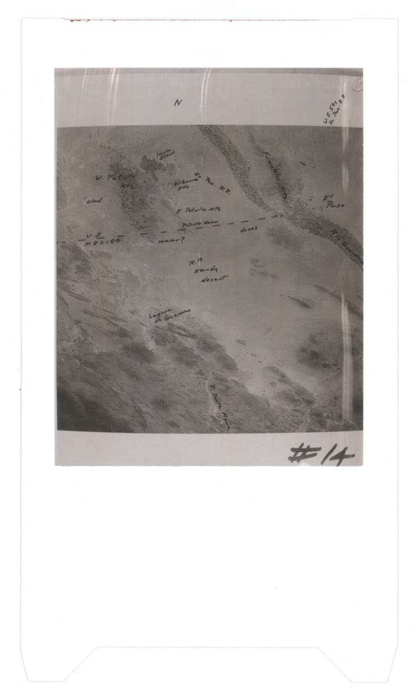
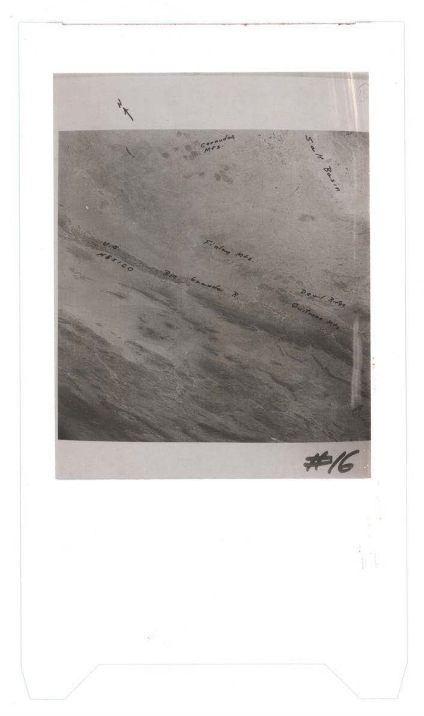
Aerial photograph with handwritten annotations including directional marker 'N', 'U.S. MEXICO' border notation, and various illegible handwritten notes; numbered '#14'
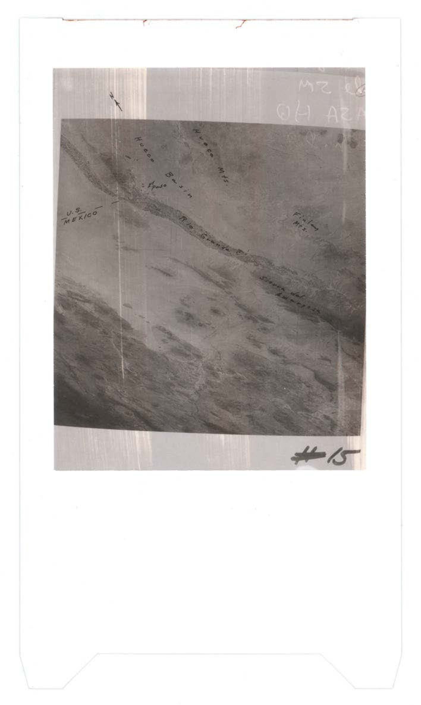
Aerial photograph showing terrain with border markings between U.S. and Mexico, with handwritten annotations and dotted lines indicating boundaries or features
Aerial photograph showing terrain with handwritten annotations including location markers and what appears to be route or boundary markings
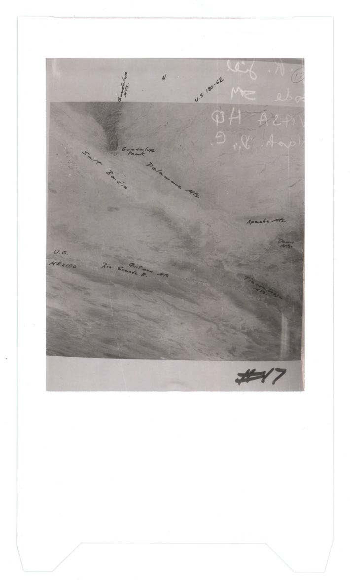
Aerial photograph showing mountainous terrain with handwritten geographic labels including Guadalupe Pass, Salt Basin, Delaware Mts, Apache Mts, and Texas State, marked as #17
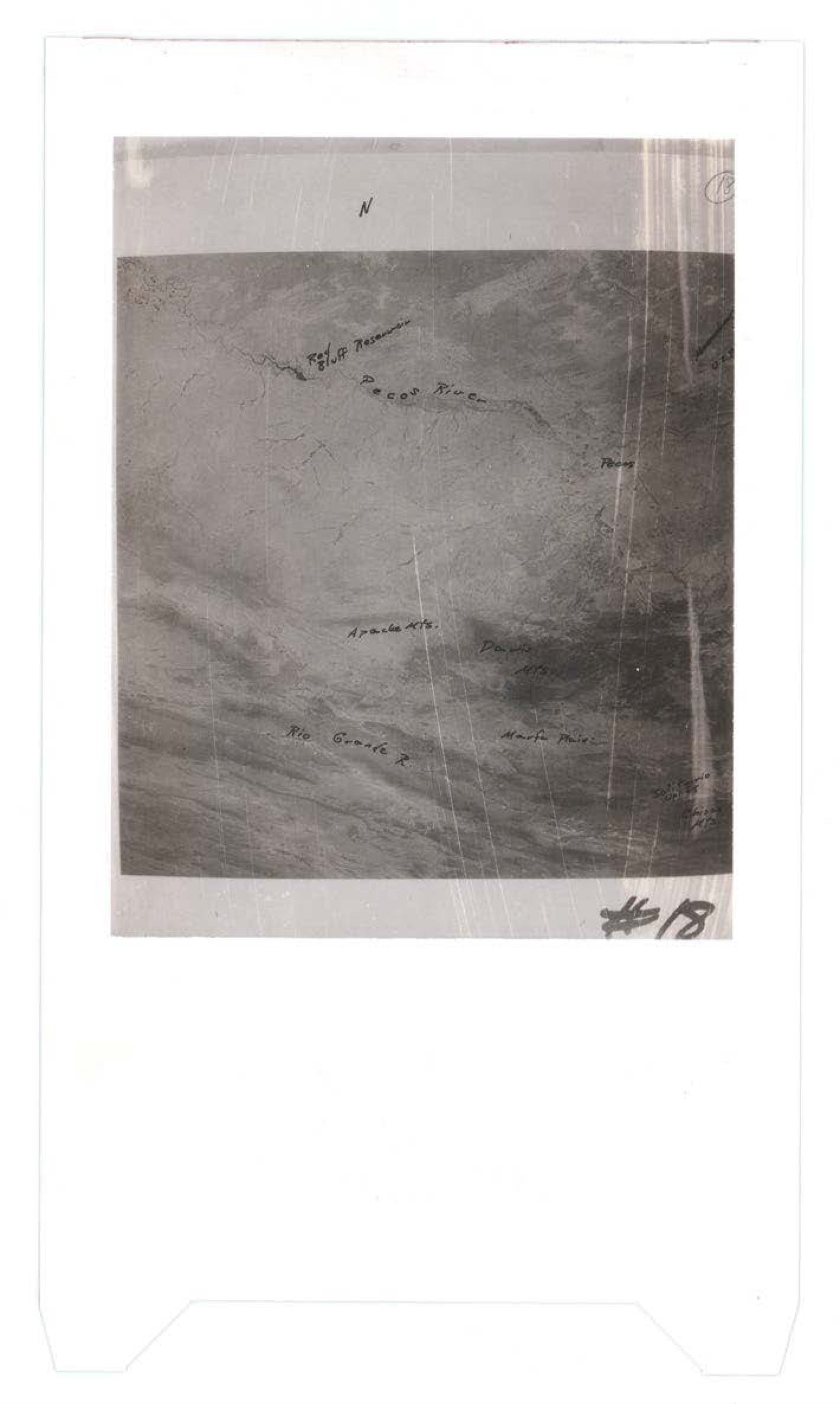
Aerial or topographic photograph with handwritten annotations indicating Old Road, Pecos River, Apache Mts., Mt. Granite, and Maria Mts., marked as #18
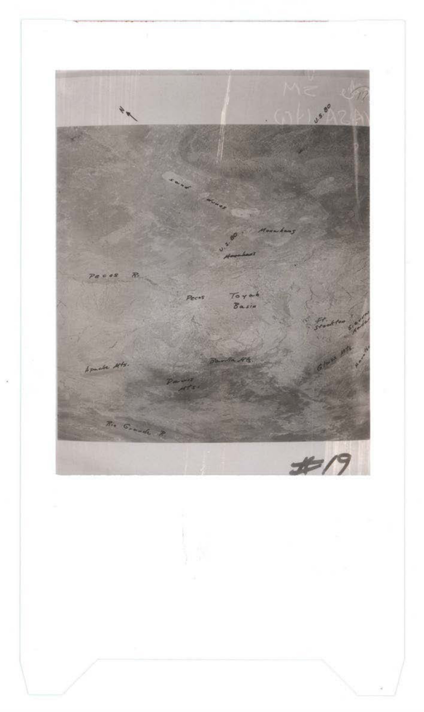
Aerial or topographic photograph with handwritten annotations marking locations including Teyuk Basin, Apache Mts., and various other geographic features
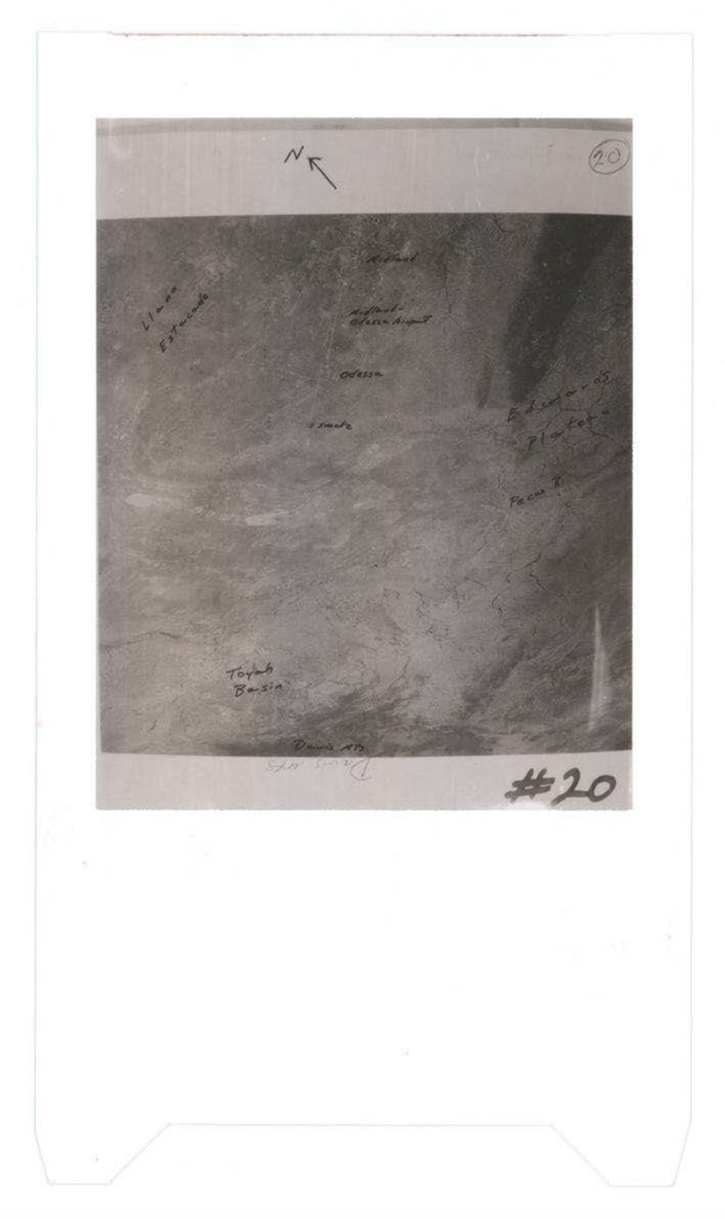
Aerial or satellite photograph with handwritten annotations indicating directional markers and geographic features including ocean
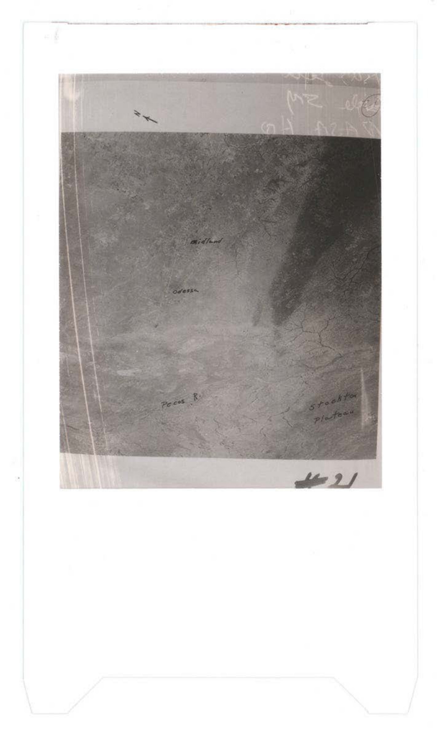
Aerial photograph showing terrain or ocean surface with aircraft silhouettes visible in upper portion and handwritten annotations
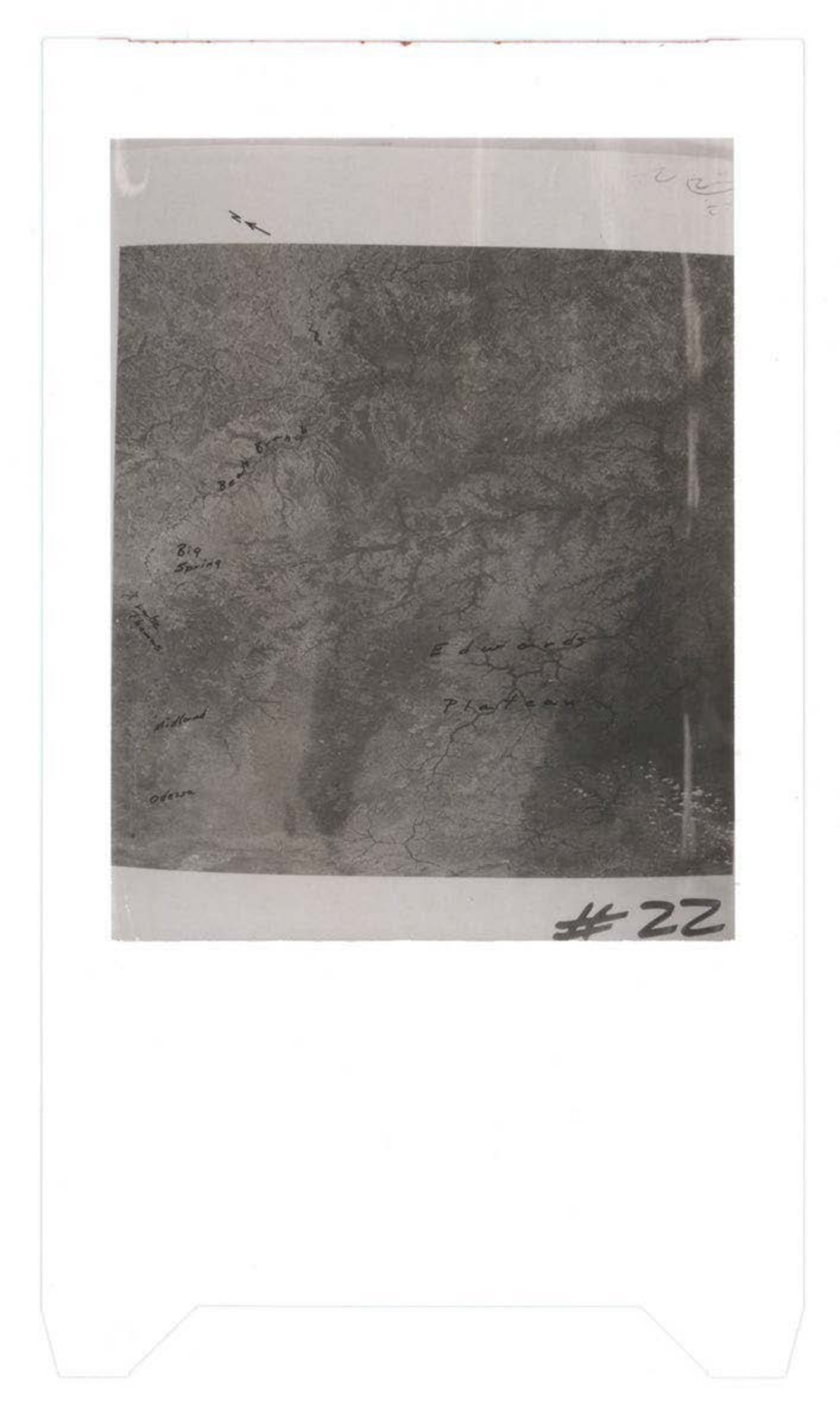
Grainy black and white photograph showing textured surface or terrain with handwritten notations and markings, labeled #22
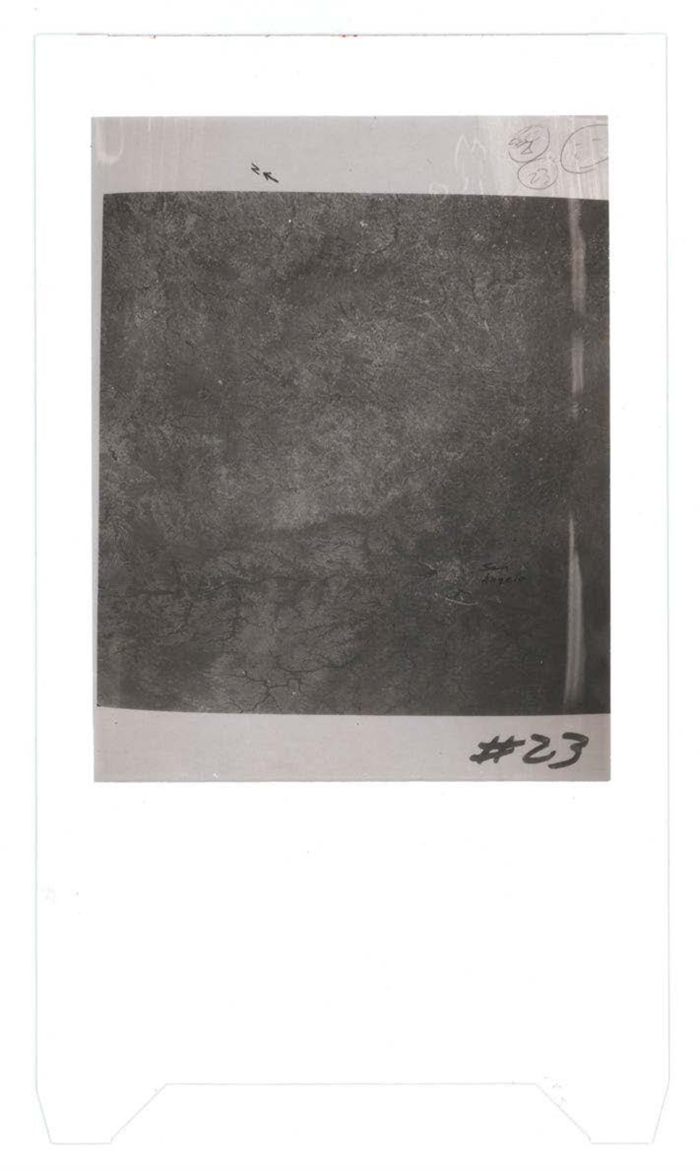
Grainy black and white photograph showing textured surface or terrain, possibly aerial or ground-level view of debris field or landscape
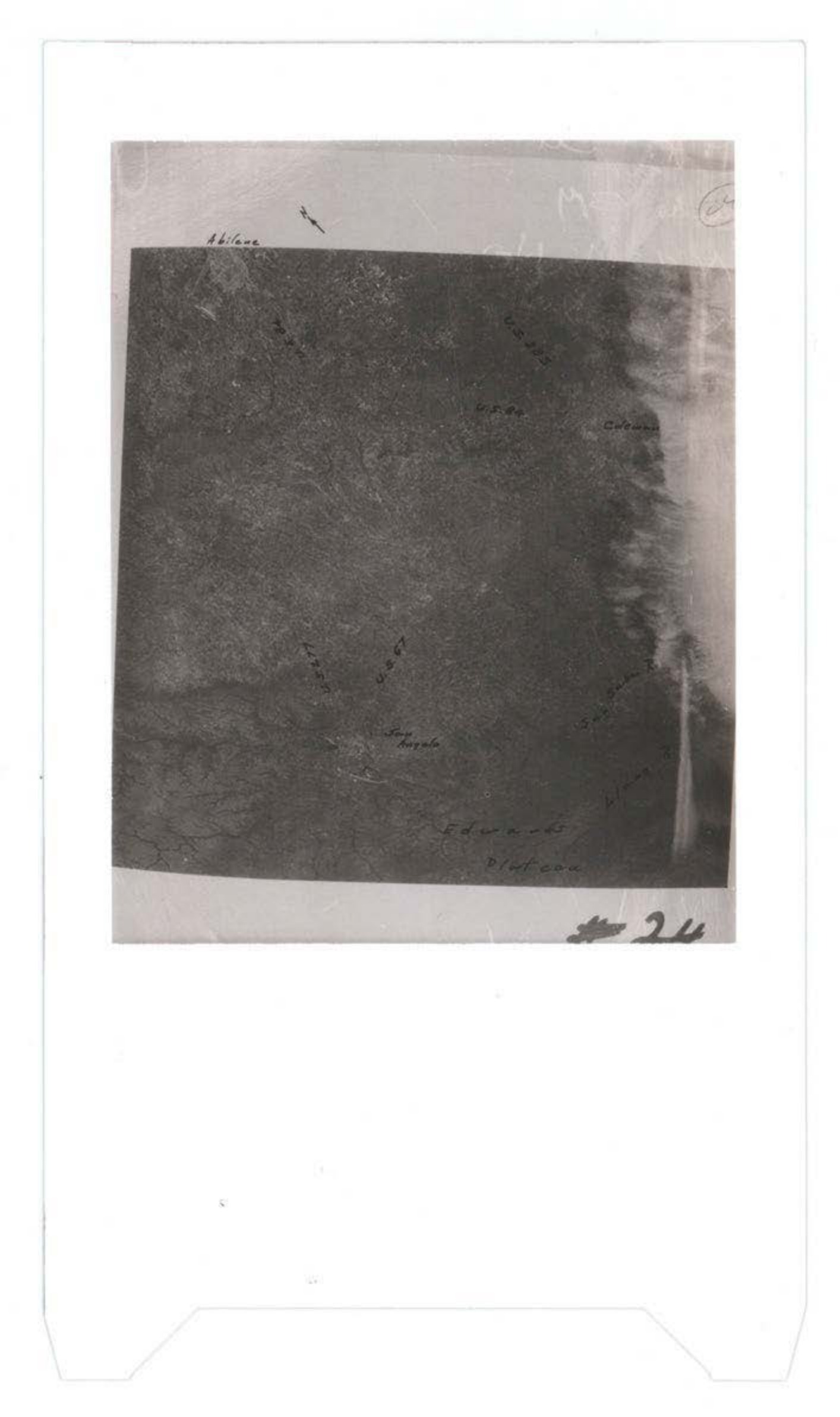
Aerial or ground photograph with handwritten annotations, appears to show terrain or debris field
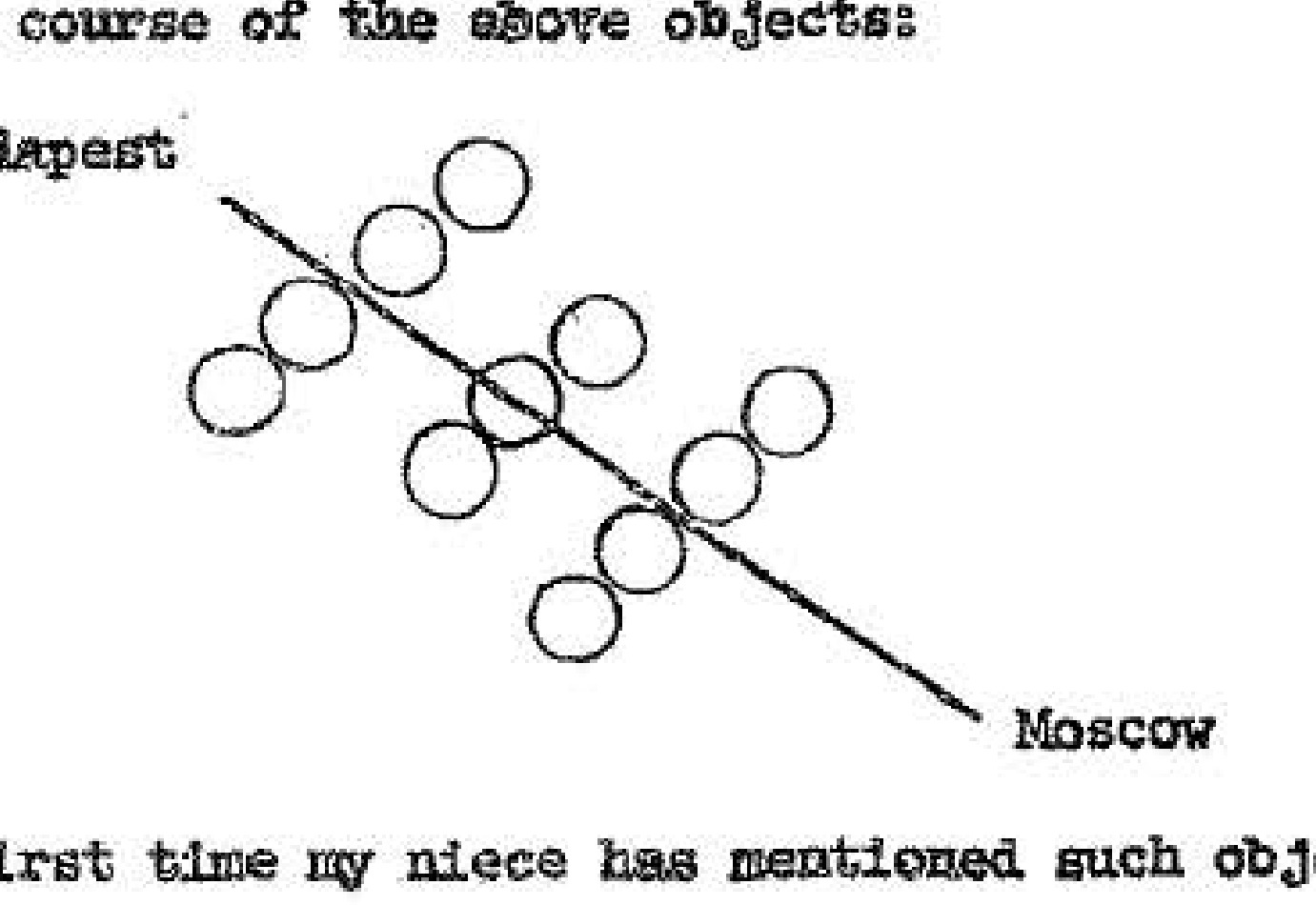
Sketch showing a formation of eight circular objects traveling from Budapest to Moscow.
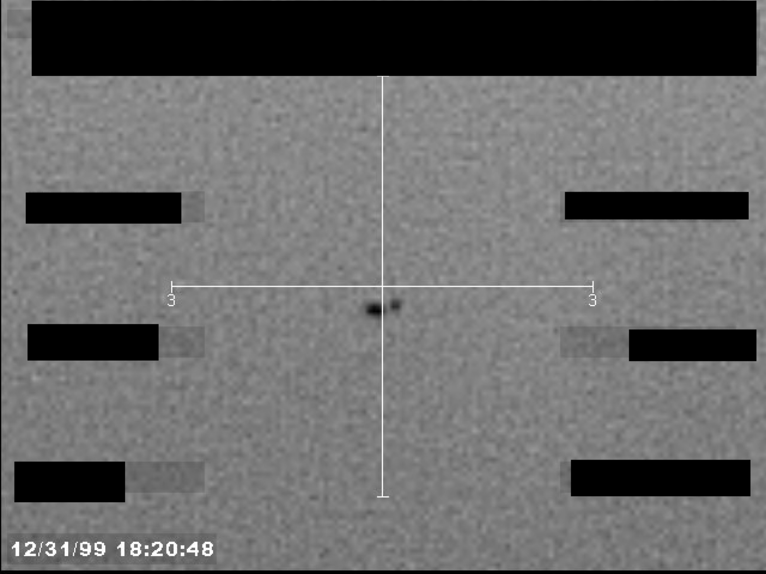
A grainy, black-and-white image, possibly from a sensor, showing a central dark object within crosshairs. A timestamp is visible in the lower-left corner, and several data fields are redacted.
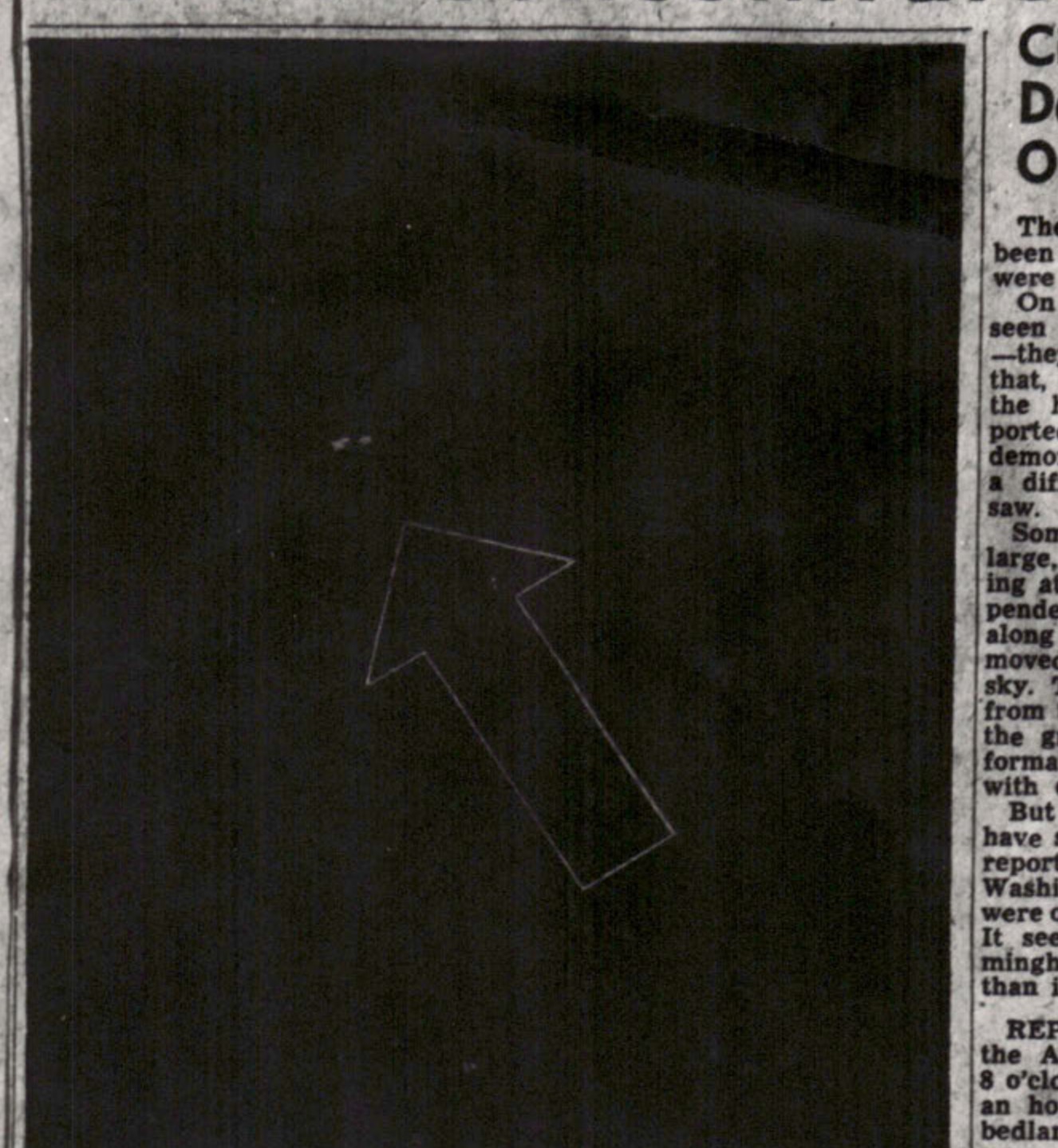
CAMERA HERE CATCHES "FLYING SAUCER"-Robert Crossland, Age-Herald copy reader, has camera proof that the much-discussed flying discs were over Birmingham last night. The picture above was made by Mr. Crossland at 8:37 p.m. last night at his home at 29th Street and Highland Avenue. He said he gave the film a 15-second exposure.
Artist's conception of the flying disc that A. C. Urie saw.
Sketch of two dark shapes, possibly tail wings.
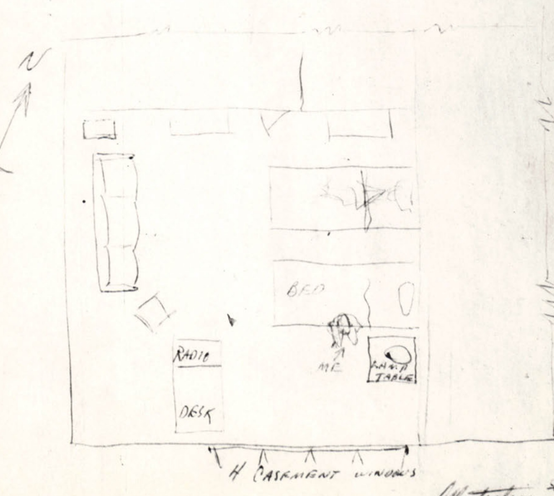
Illustration No. 1, a hand-drawn layout of a room.
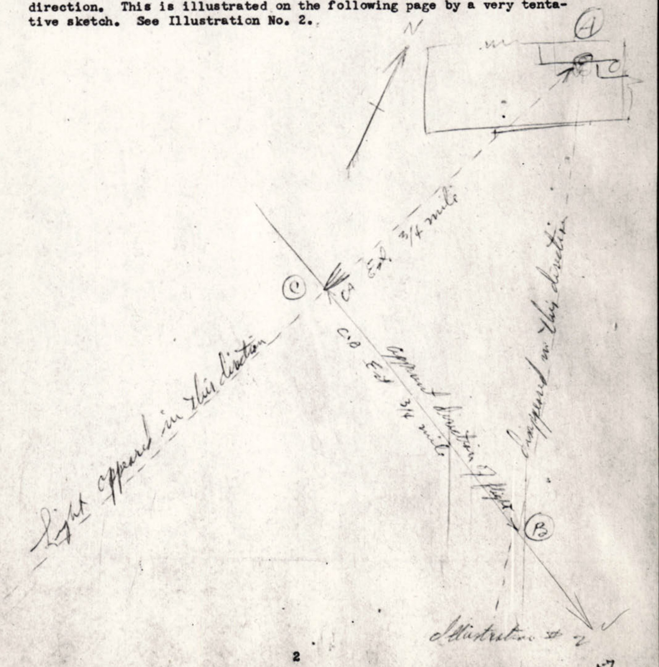
Illustration No. 2, a hand-drawn sketch of the object's flight path.
A black square with a white border, possibly a placeholder or negative.
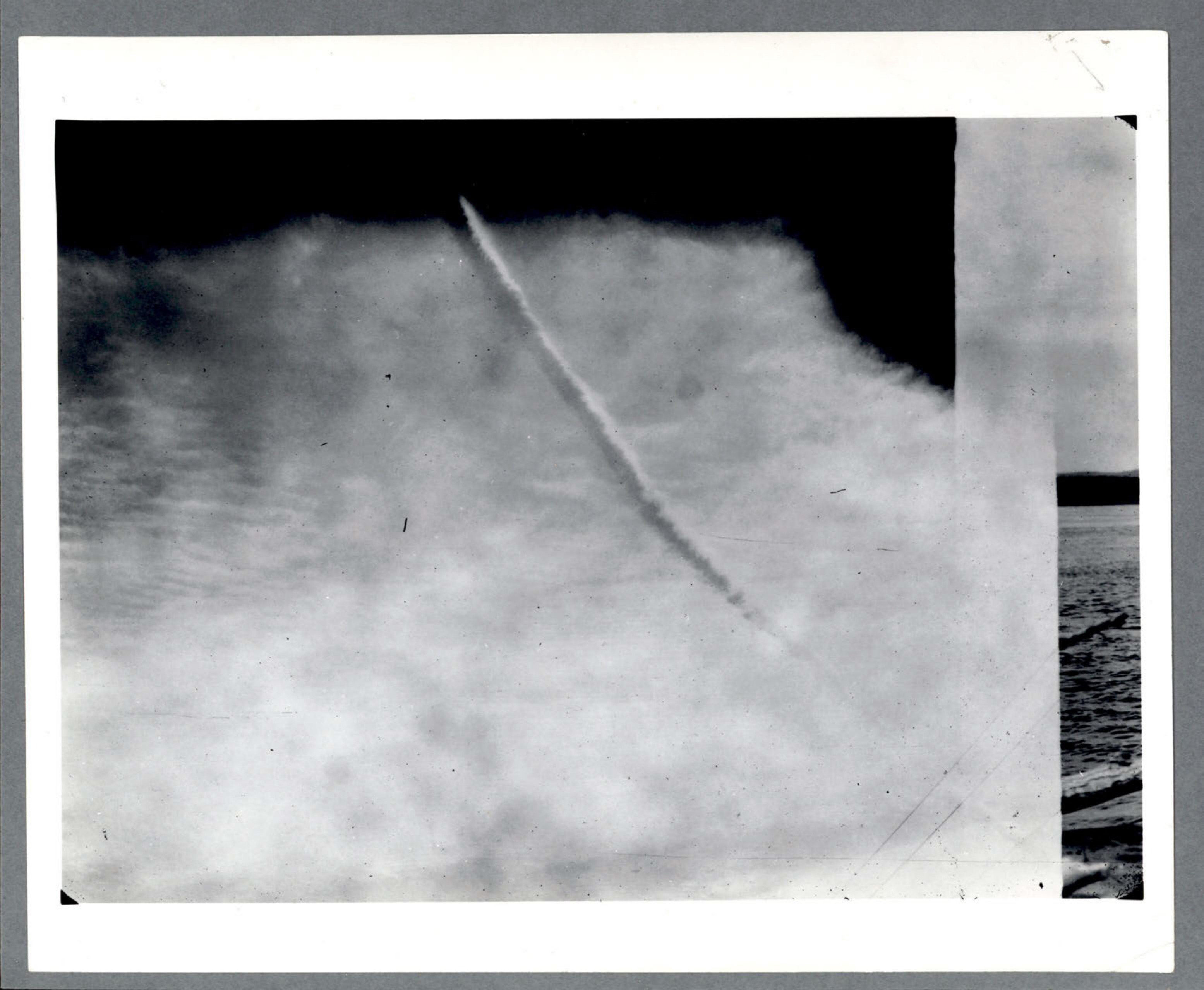
Photograph of a contrail or object trail in a cloudy sky.
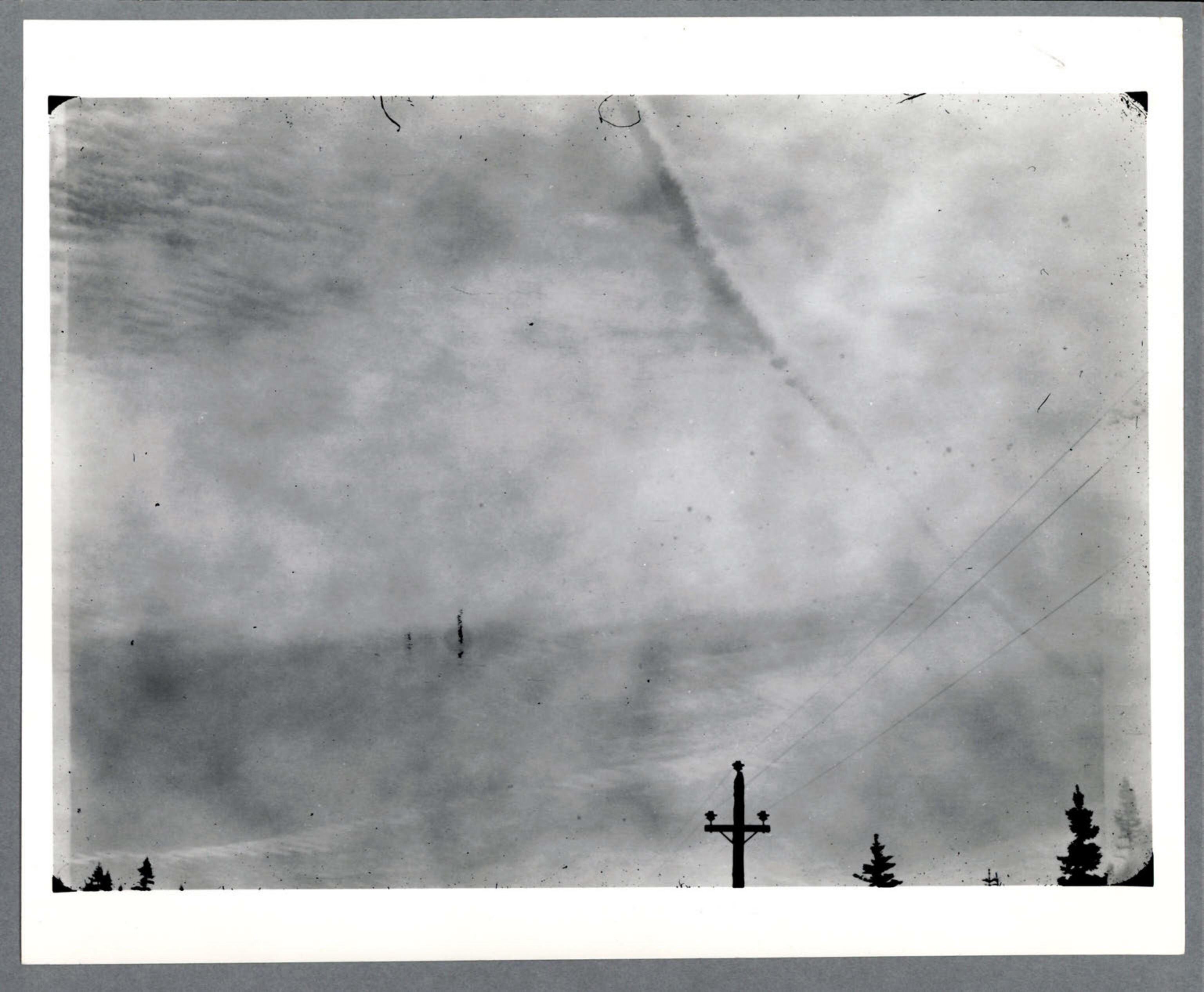
Photograph of a contrail in a cloudy sky, with power lines and trees in the foreground.
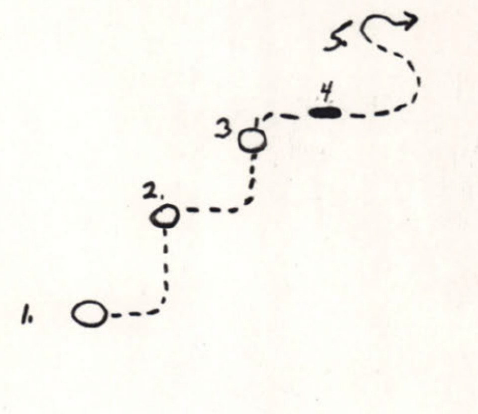
A hand-drawn diagram showing the erratic flight path of an object, labeled with numbers 1 through 5.
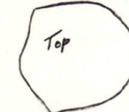
A hand-drawn sketch of the object's shape, labeled 'Top' and 'Side View'.
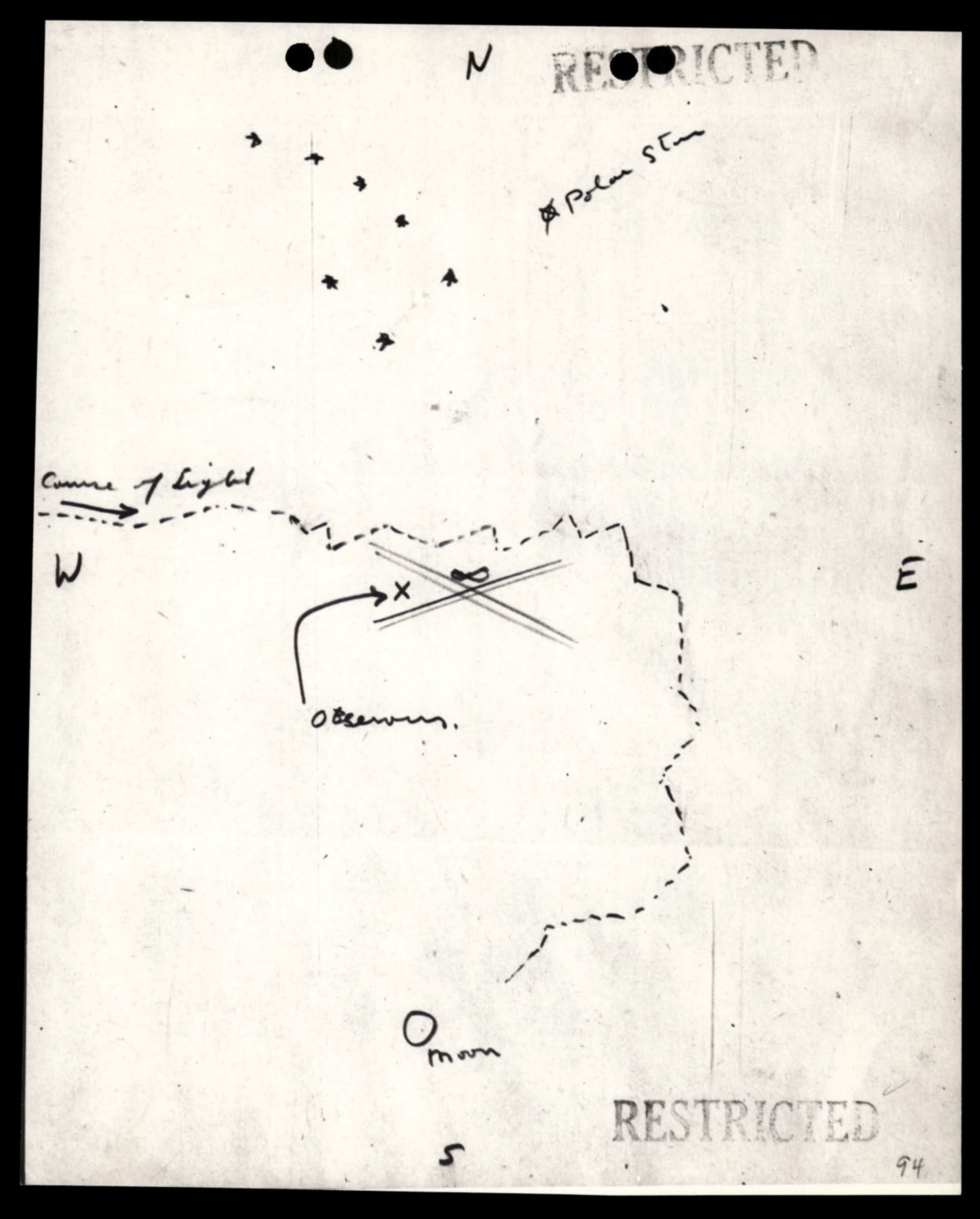
A hand-drawn map showing the path of a light relative to the observers, the moon, and the Polar Star.
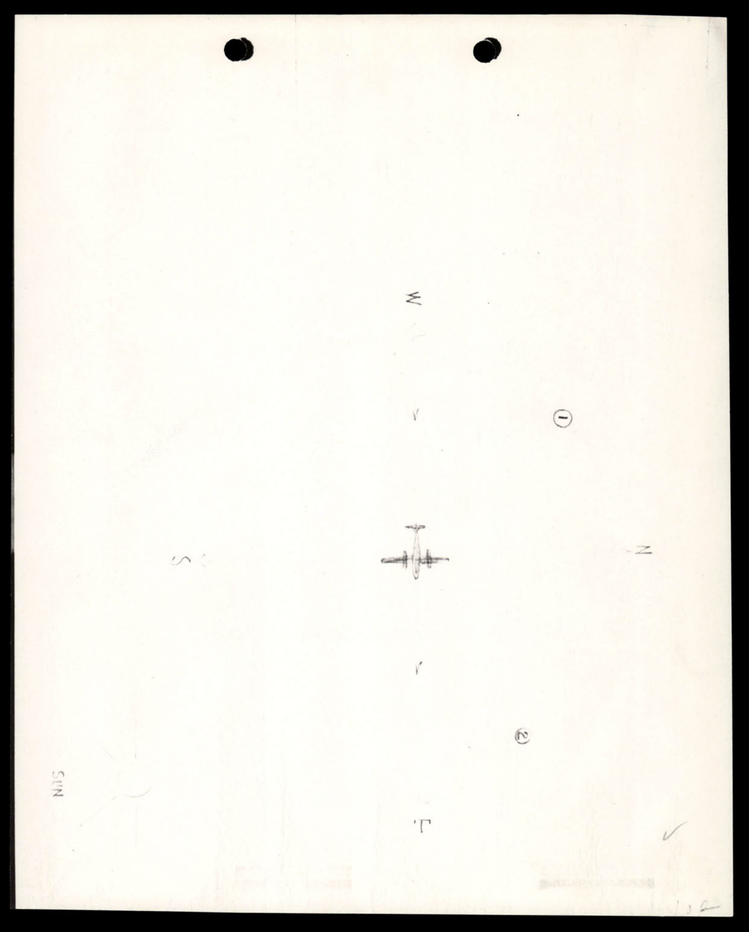
A hand-drawn diagram showing the position of an object (1) and (2) relative to a B-25 airplane, with cardinal directions and the sun's position indicated.

Seal of the Department of War, Intelligence and Security.
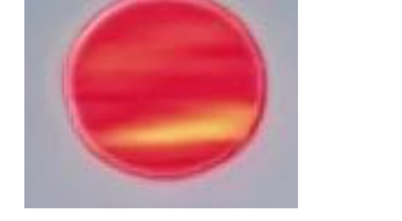
Artist Rendering
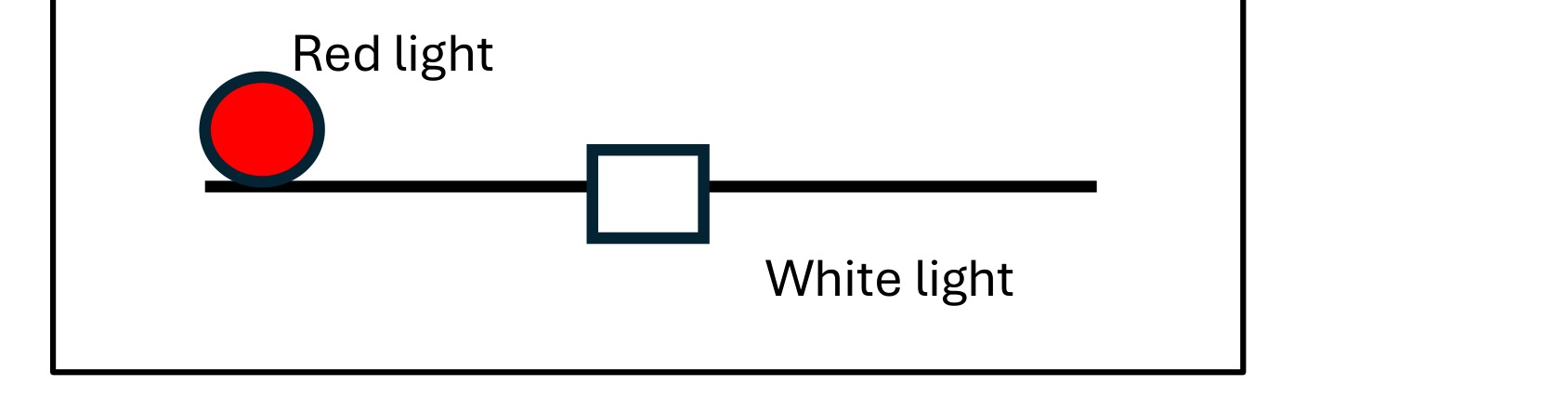
Image 1: Recreation of drawing provided by USPER6 of object seen in night vision goggles.
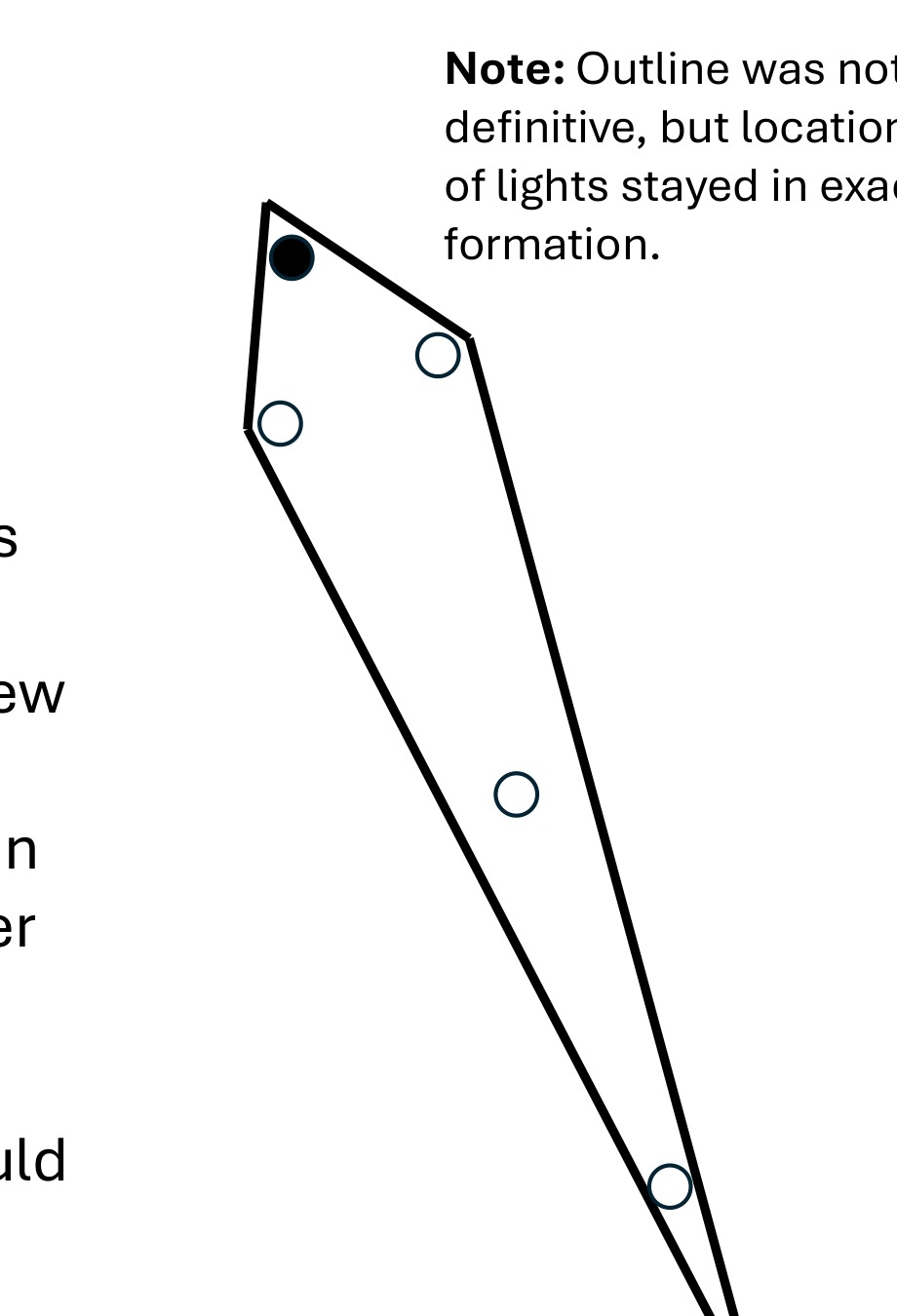
Image 2: Recreation of drawing provided by USPER6 of object seen with the bare eye.
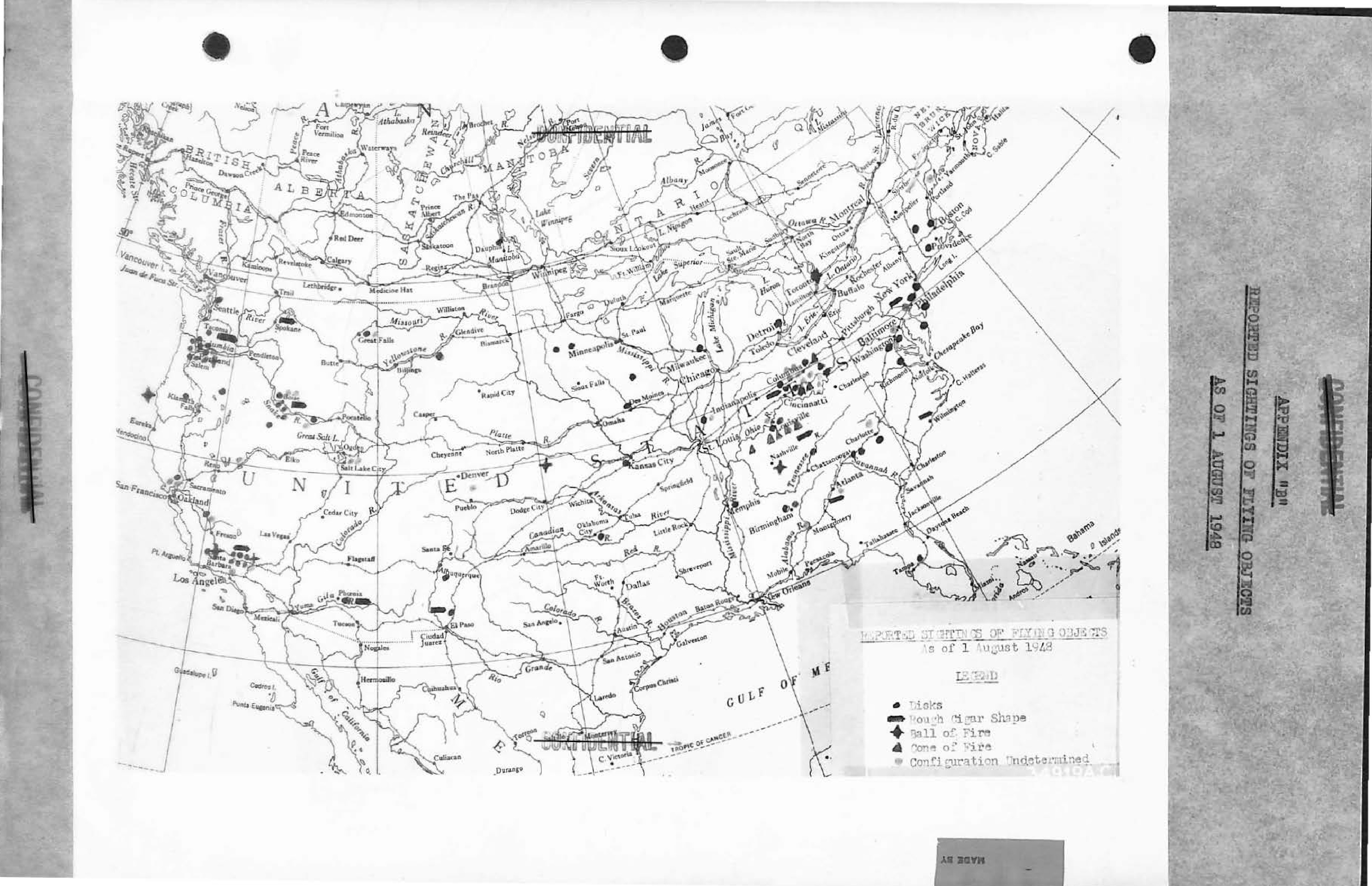
Map of North America showing reported sightings of flying objects as of 1 August 1948.

Fig. 1

Fig. 2
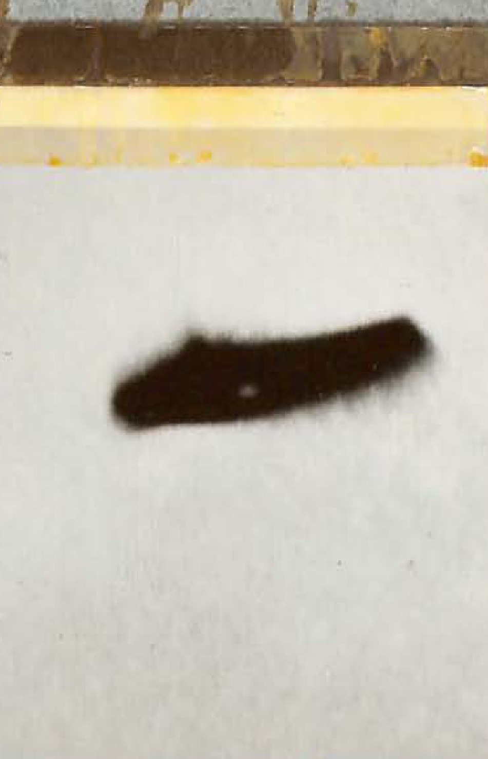
Fig. 3
Fig. 4
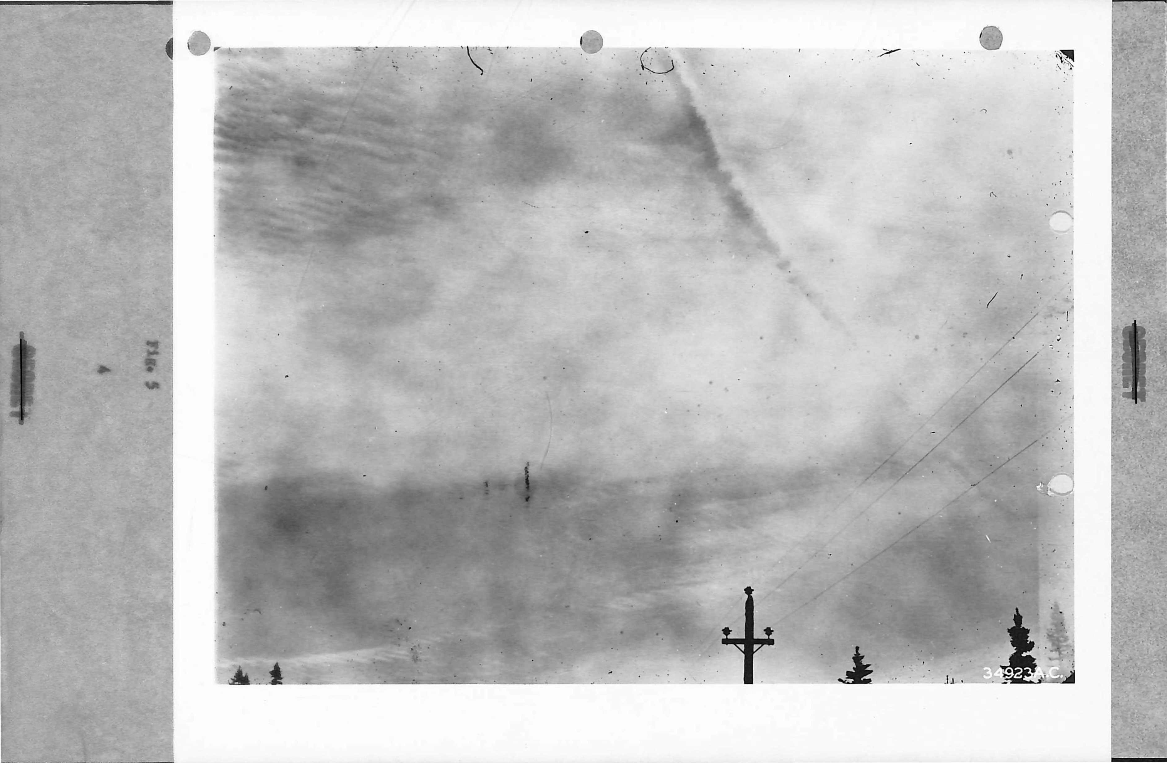
Fig. 5 - Trail in cloudy sky.
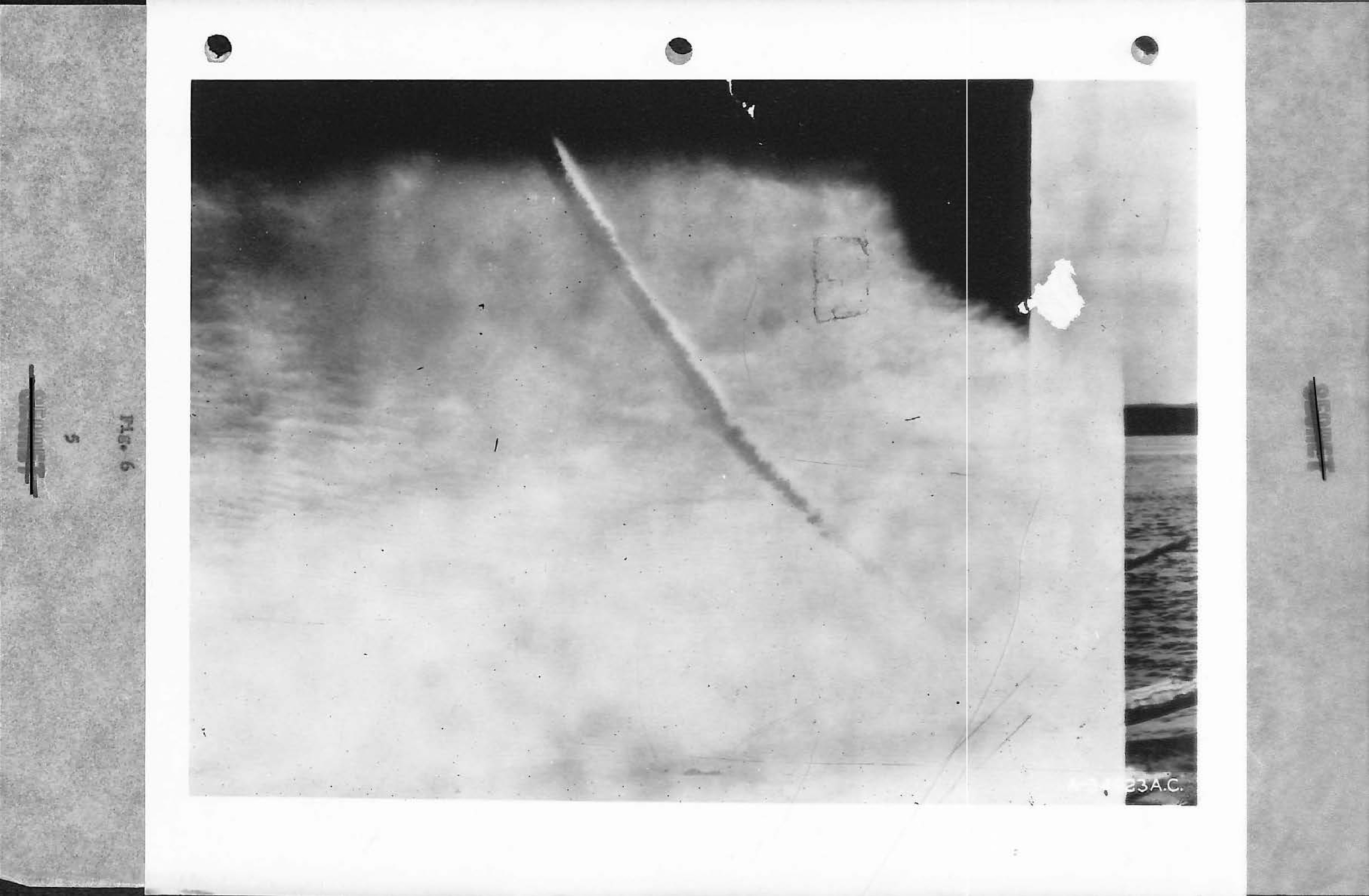
Fig. 6 - Trail in cloudy sky.
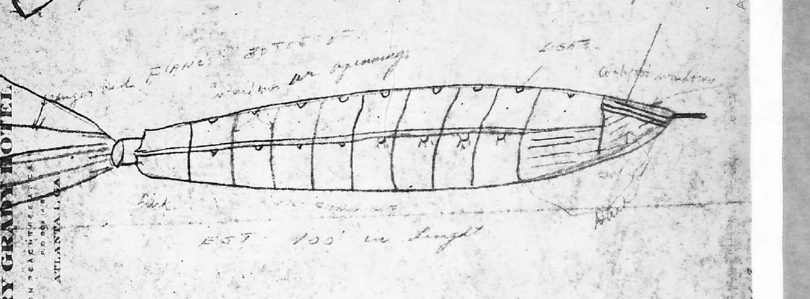
Sketch of a long, cylindrical object with a tail flame and windows, drawn on hotel stationery.
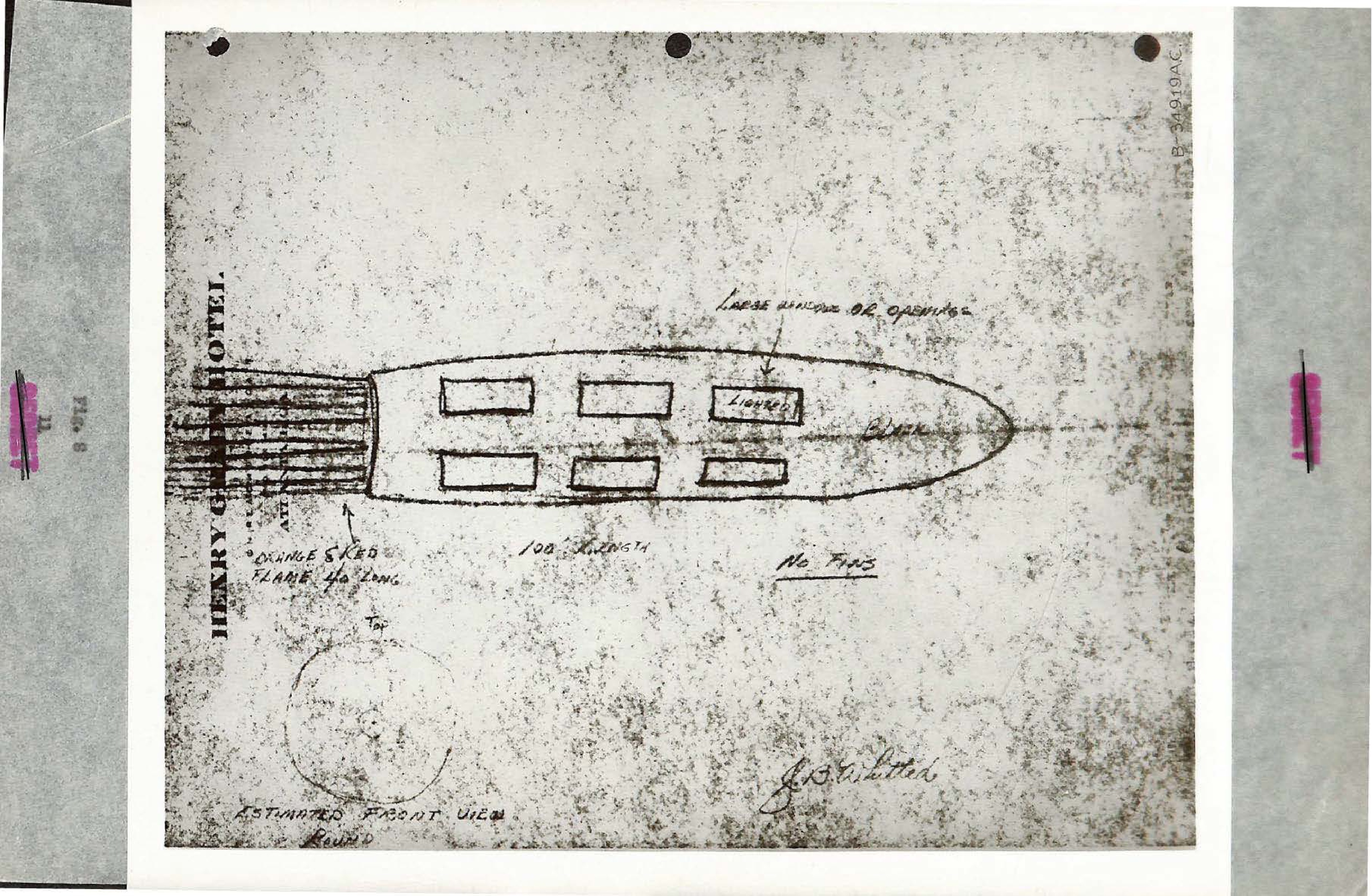
Photograph of a sketch of a cylindrical object with windows and a tail flame.
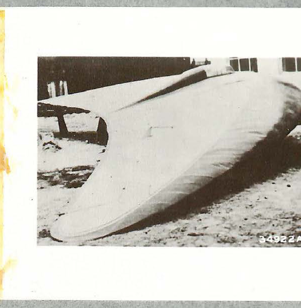
Photograph of a Horten glider on the ground. Number on photo: 34922A.C.
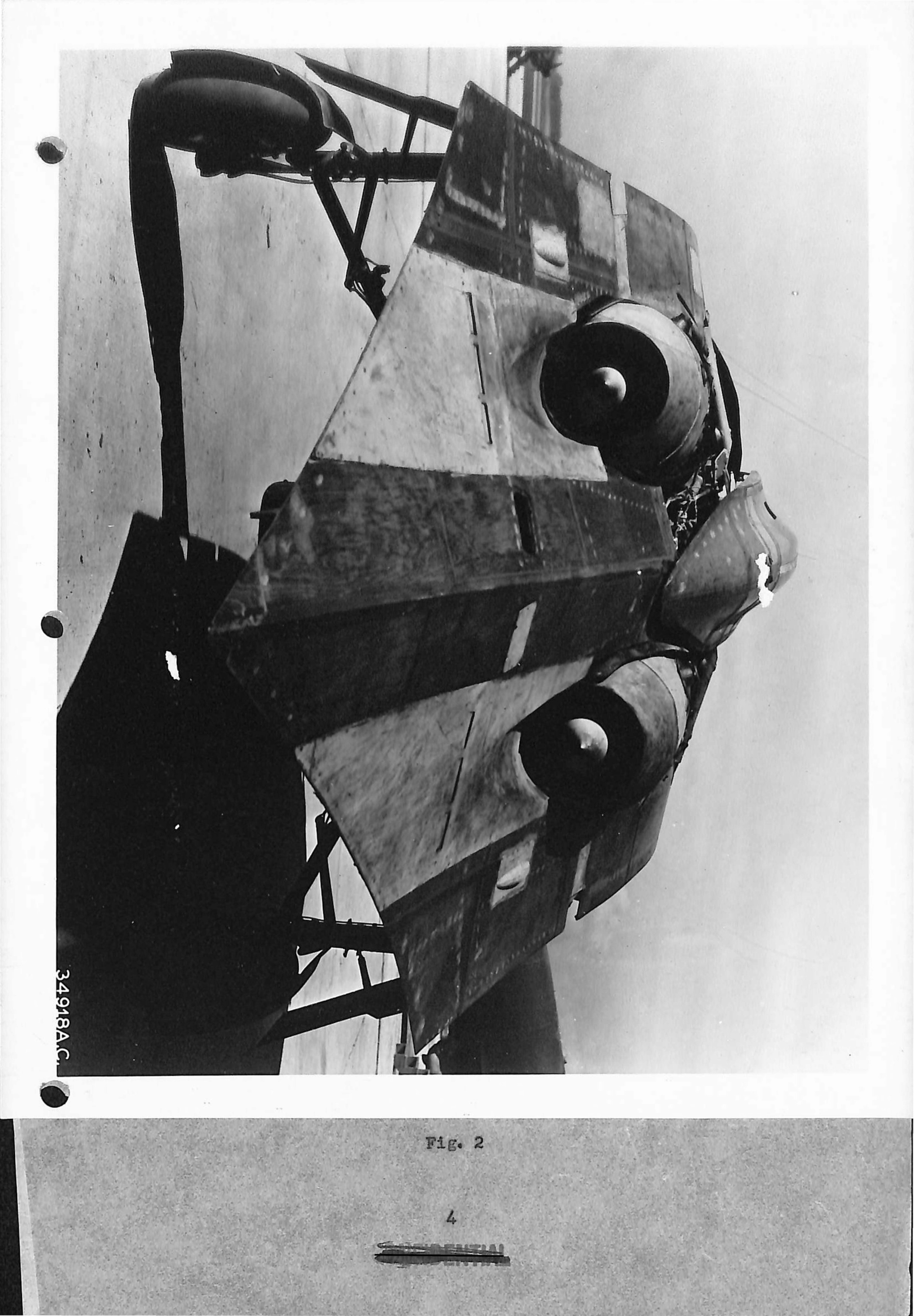
Photograph of the Horten 229 flying wing aircraft, showing the twin jet engines.
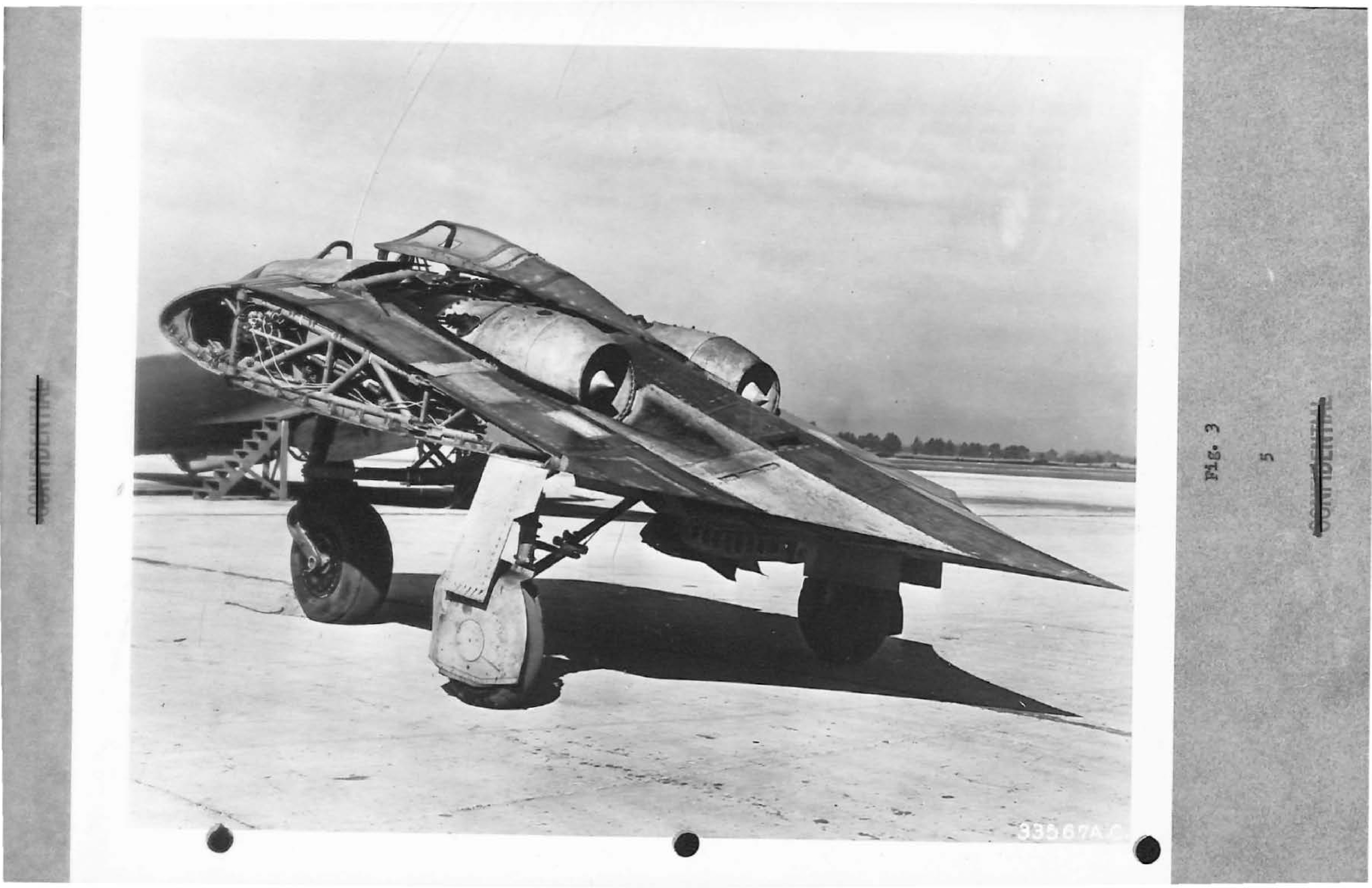
Photograph of the Horten 229 aircraft on the ground.
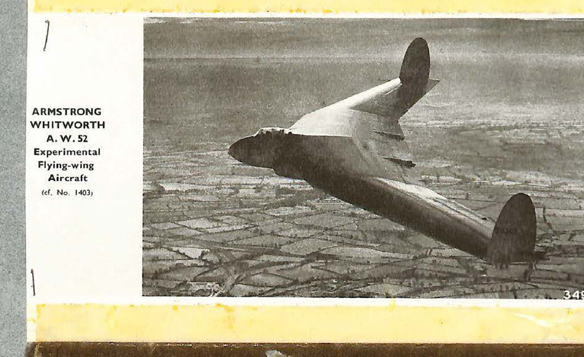
ARMSTRONG WHITWORTH A. W. 52 Experimental Flying-wing Aircraft (cf. No. 1403). Number on photo: 34925A.C.
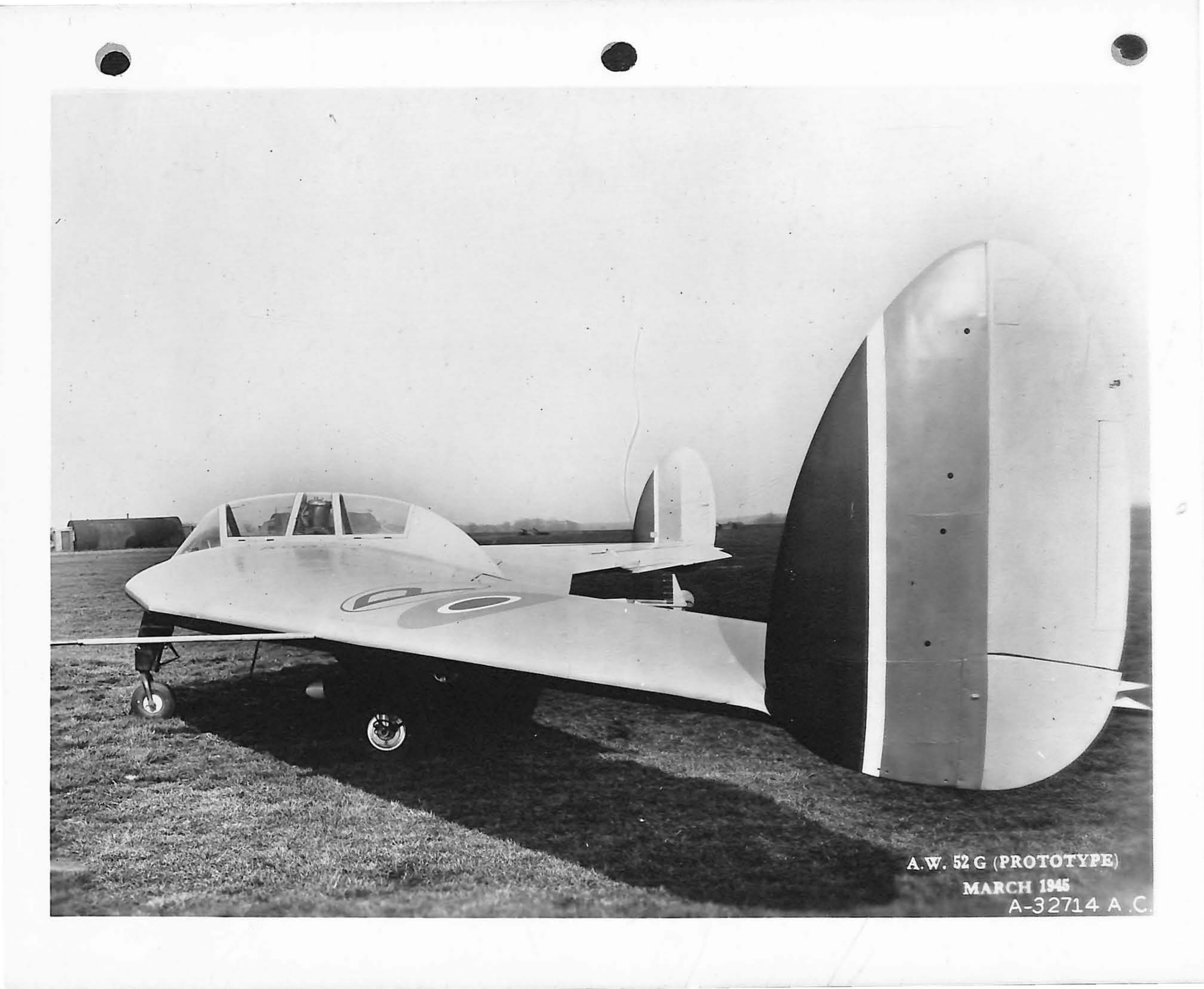
A.W. 52 G (PROTOTYPE) MARCH 1945 A-32714 A.C.
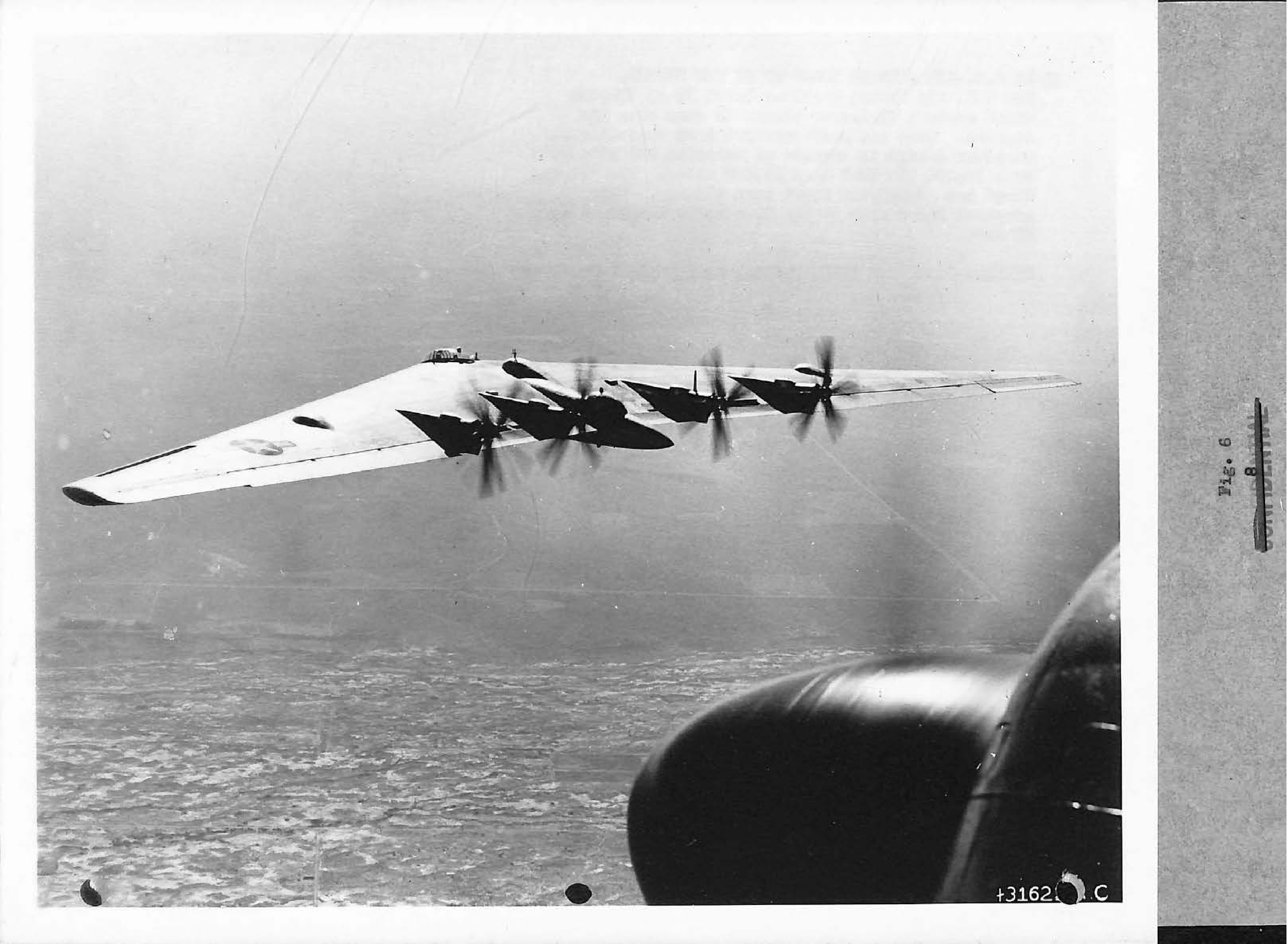
Photograph of the Northrop XB-35 flying wing in flight.
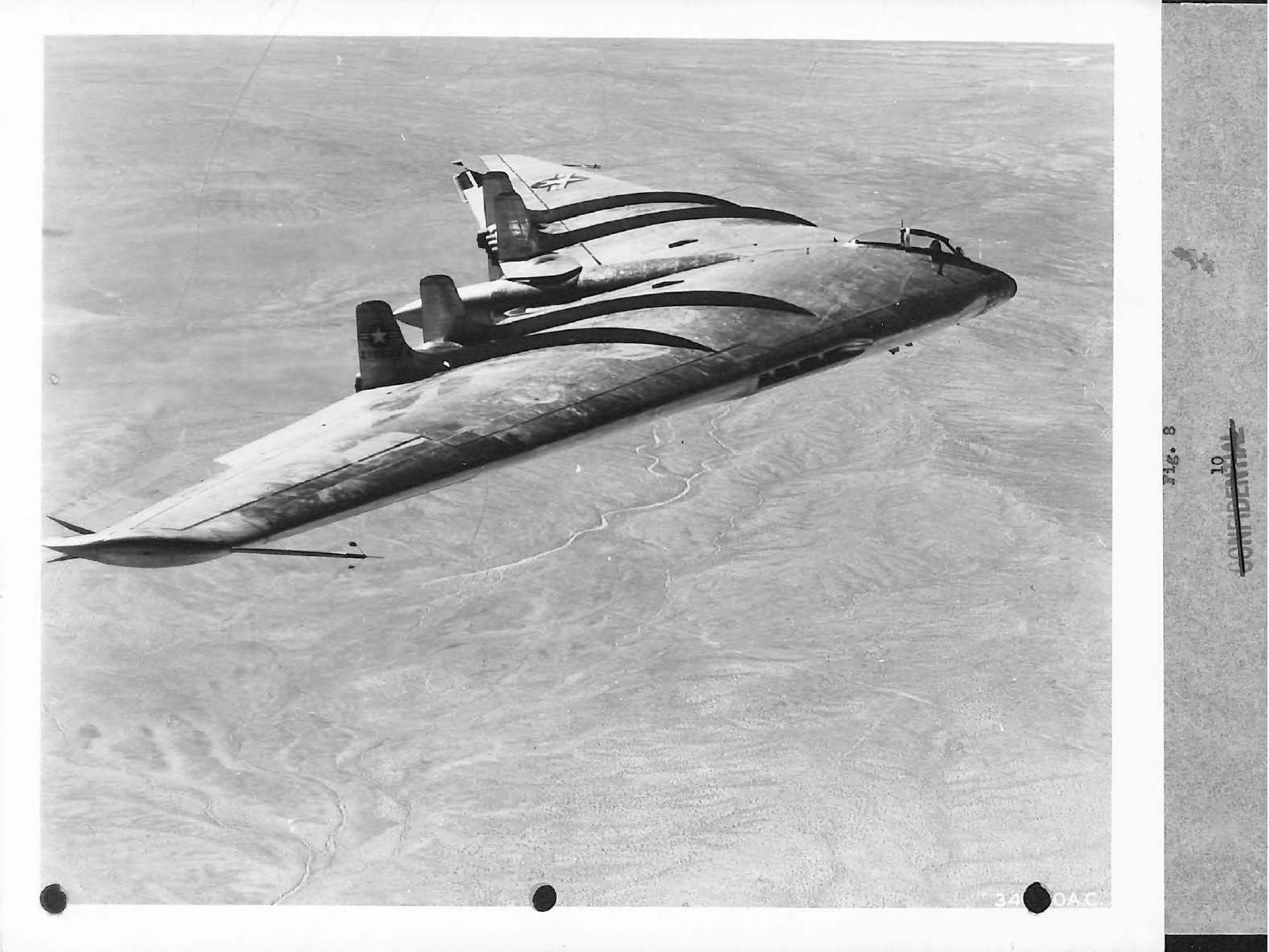
Photograph of the Northrop YB-49 flying wing in flight.
Faint image of an aircraft, likely the Chance-Vaught XF5U-1.
Faint image, possibly a diagram or second view of the aircraft.
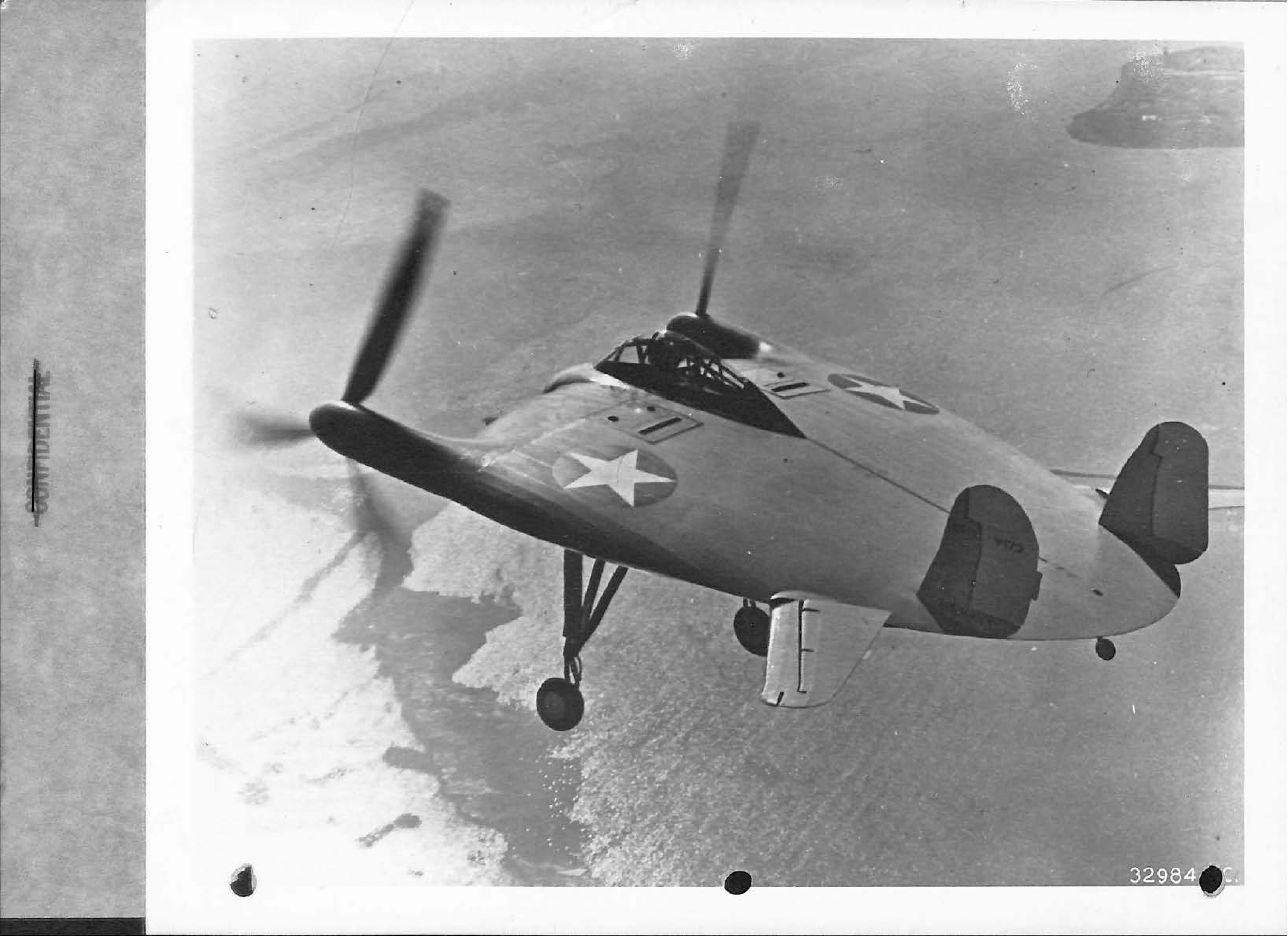
Photograph of the Chance-Vought XF5U-1 experimental aircraft in flight over water.
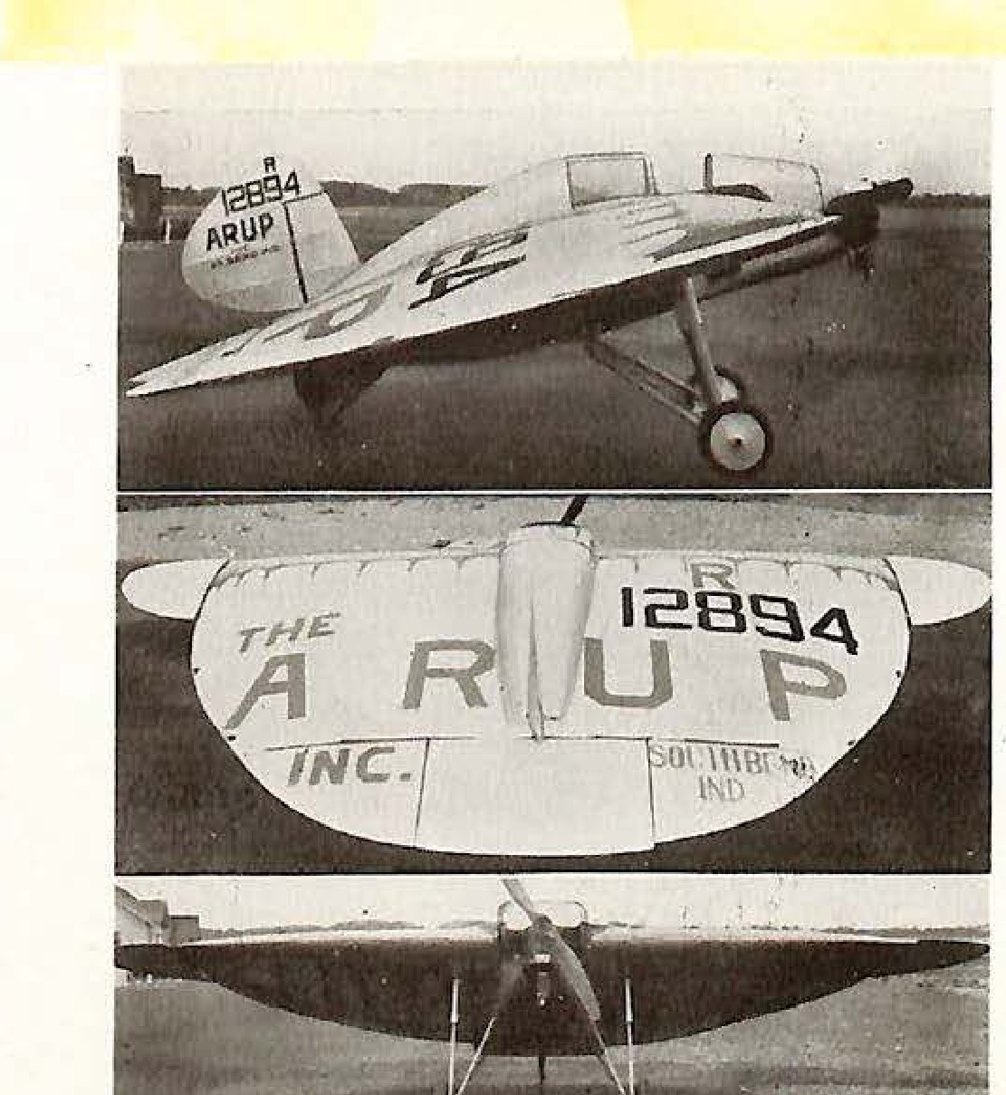
Three views of an Experimental Arup tailless Monoplane. Markings include '12894 ARUP' and 'THE ARUP INC. SOUTHBEND IND.'
This page is the verso of a photograph, containing only stamps.
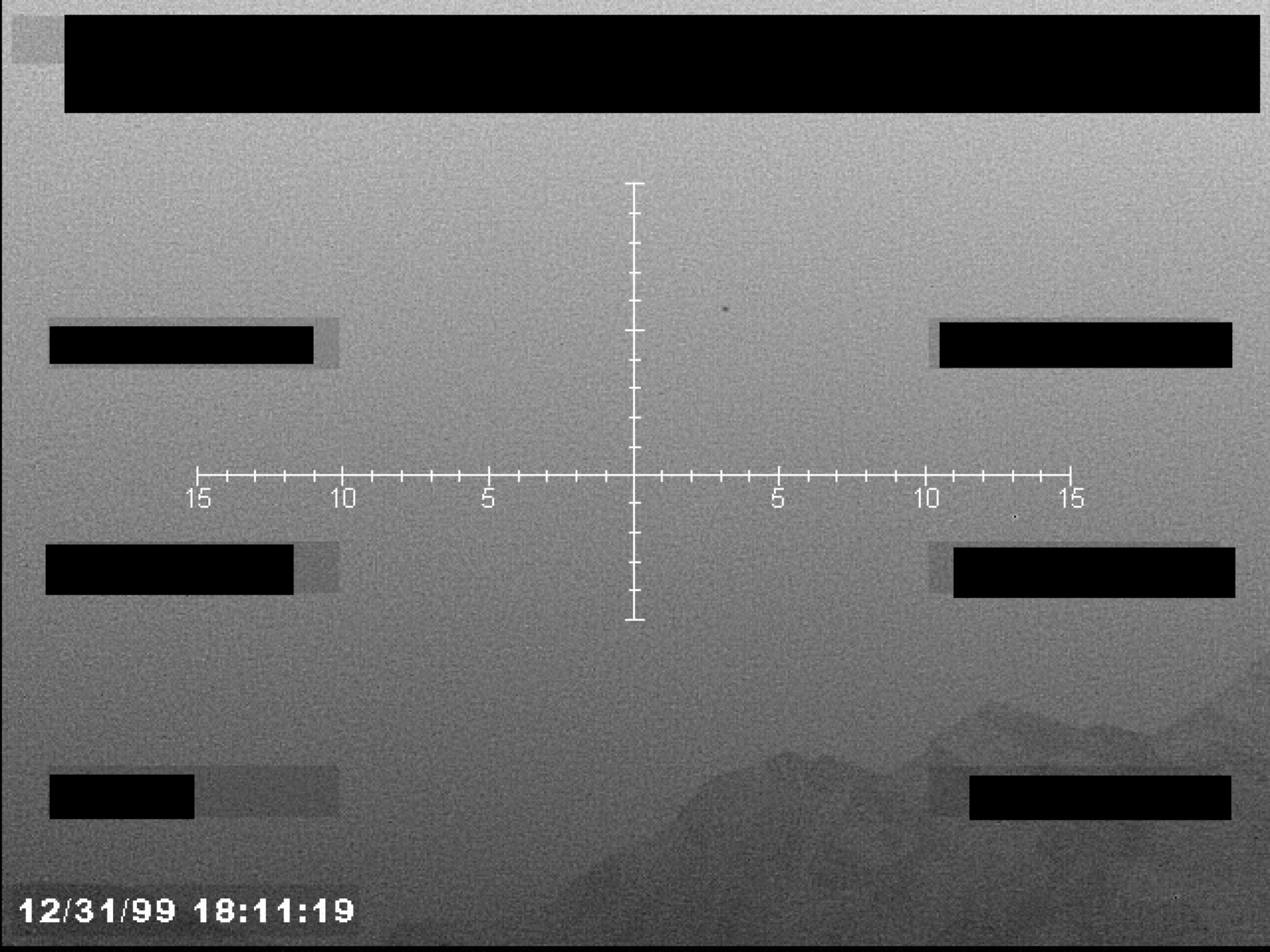
Sensor or gun camera view with a central crosshair reticle, timestamp, and multiple redactions.
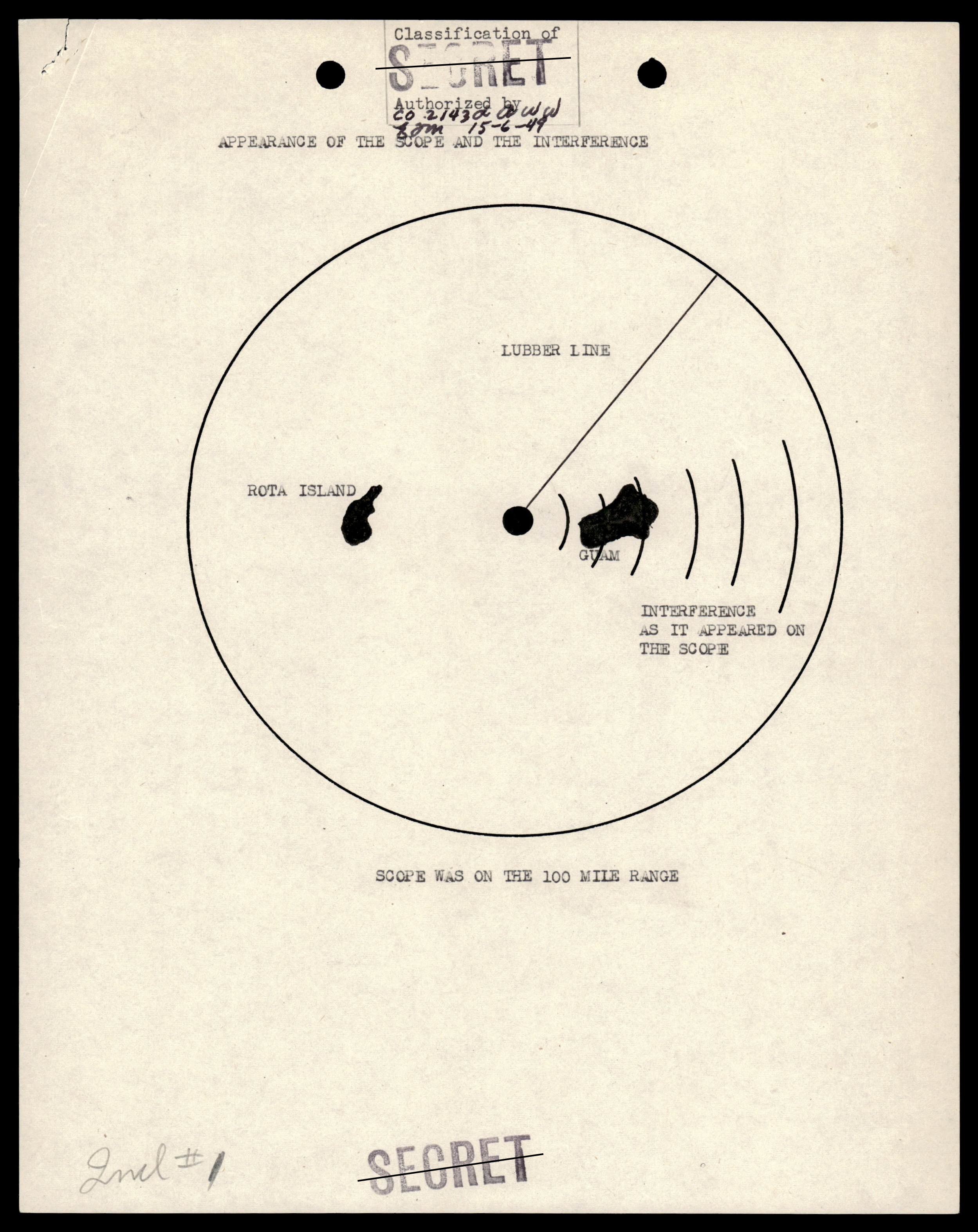
Diagram of a radar scope showing interference near Guam and Rota Island.
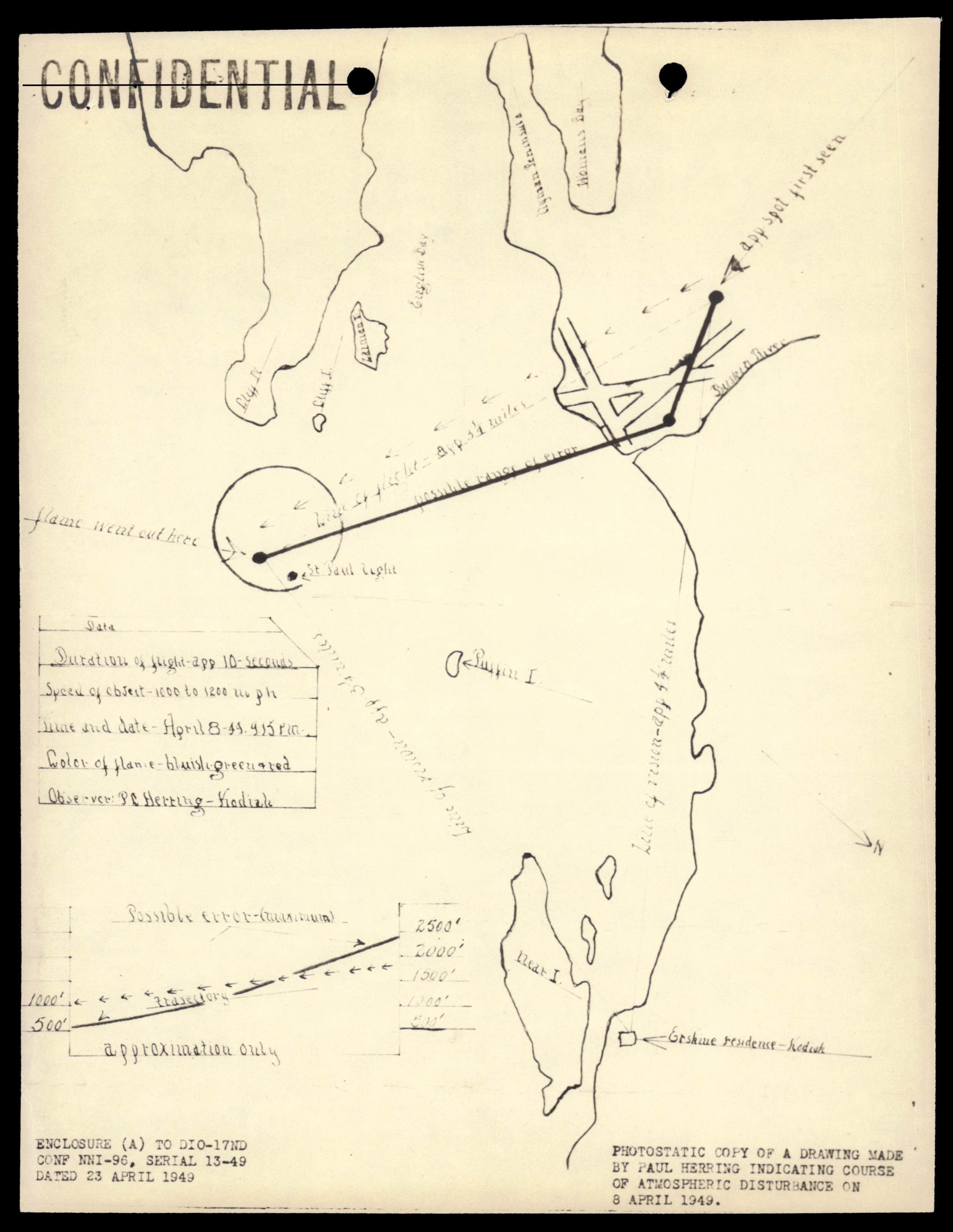
Hand-drawn map by Paul Herring indicating the course of a luminous object over Kodiak, Alaska on 8 April 1949.
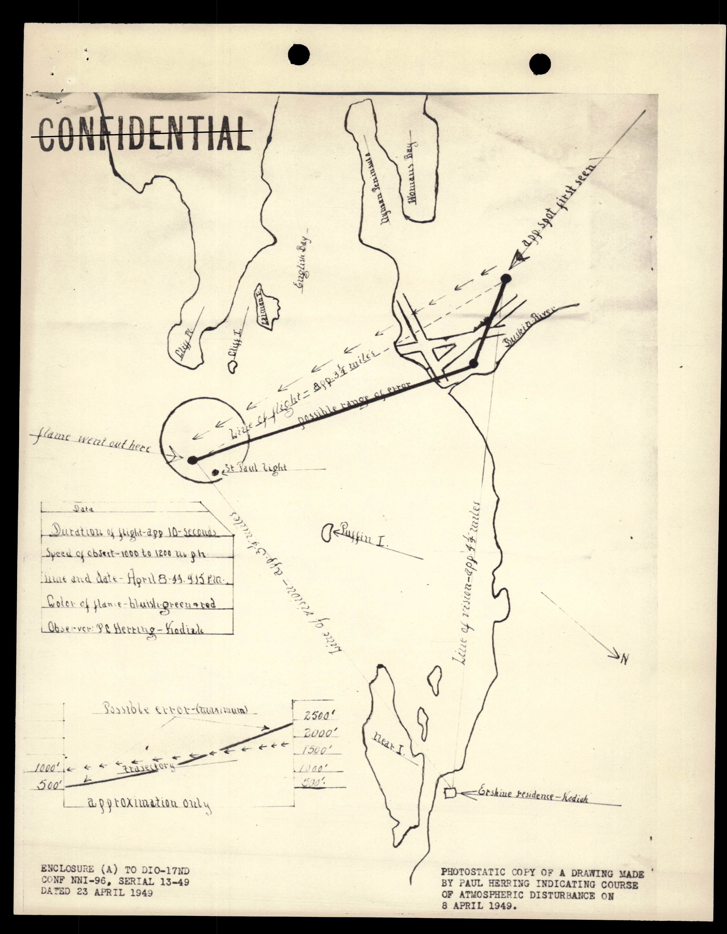
Photostatic copy of a hand-drawn map by Paul Herring indicating the course of a luminous object over Kodiak, Alaska on 8 April 1949.
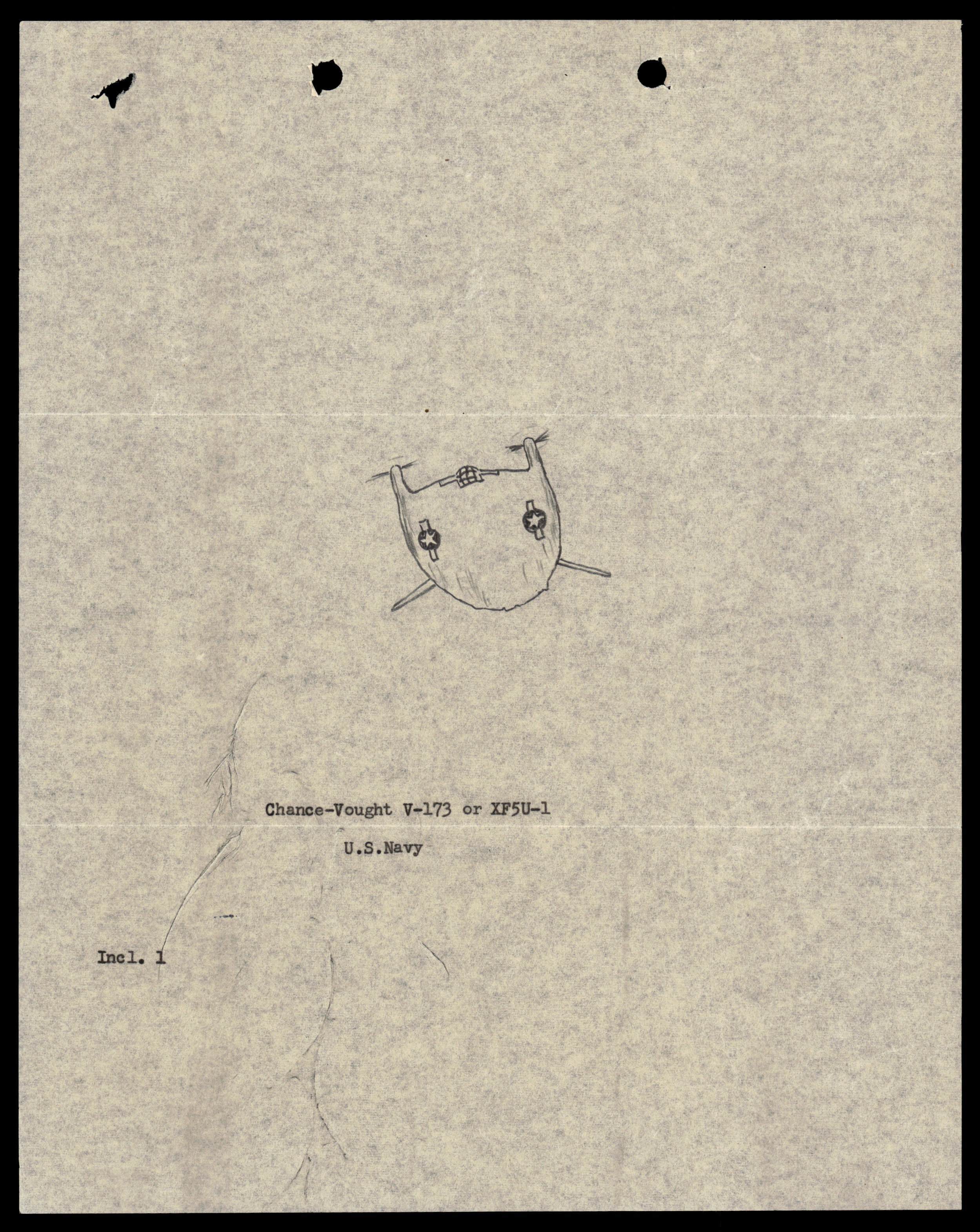
Sketch of the Chance-Vought V-173 or XF5U-1 aircraft.
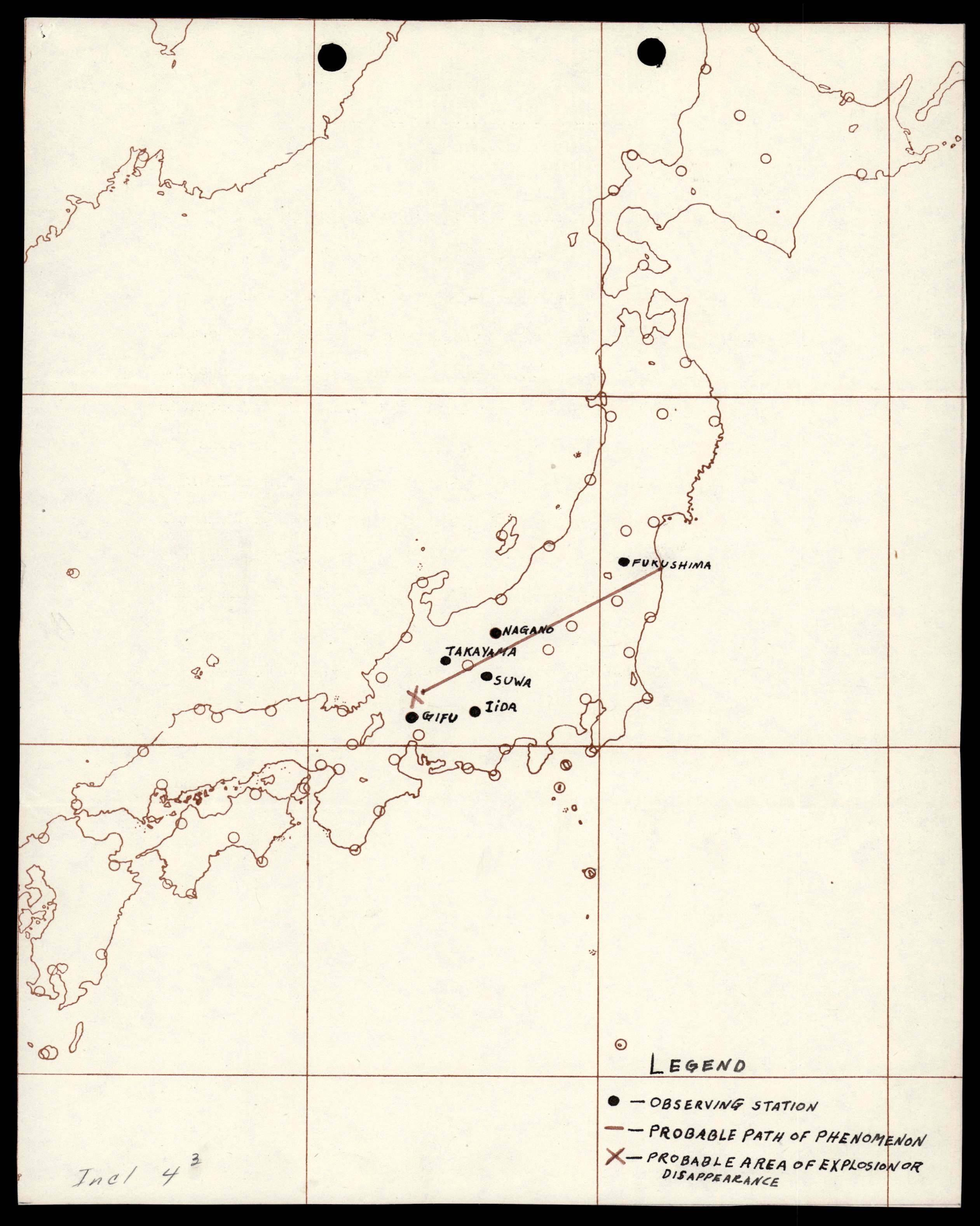
Hand-drawn map of Japan showing the locations of weather stations that observed a phenomenon, its probable path, and area of explosion or disappearance.
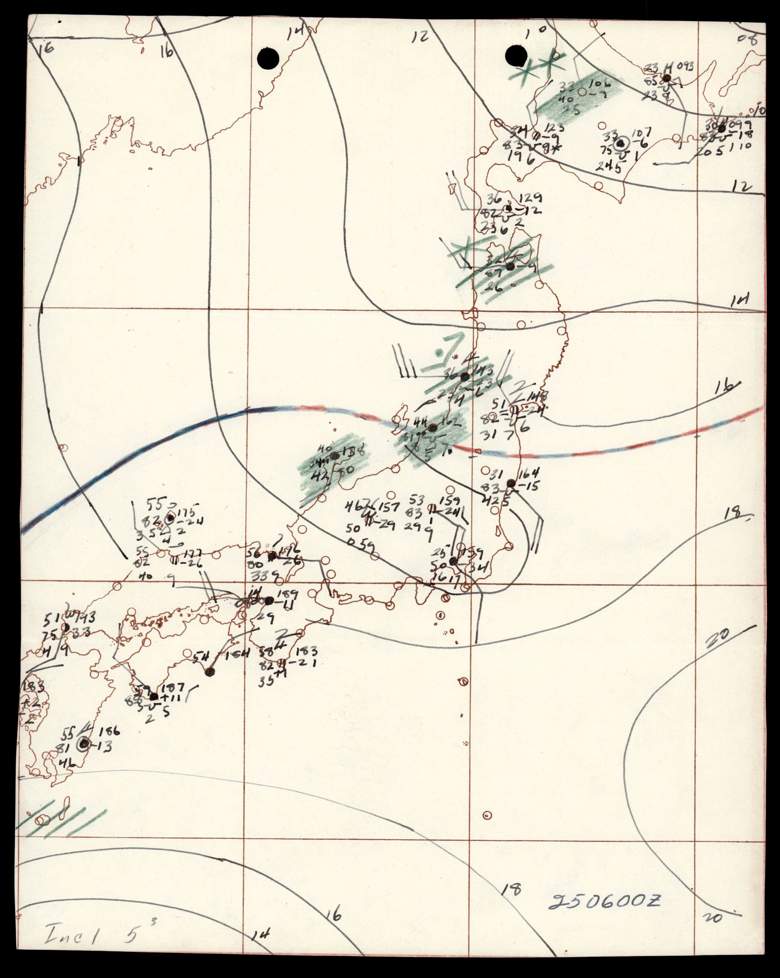
Hand-drawn surface synoptic weather chart for 25 January 0600Z over Japan.
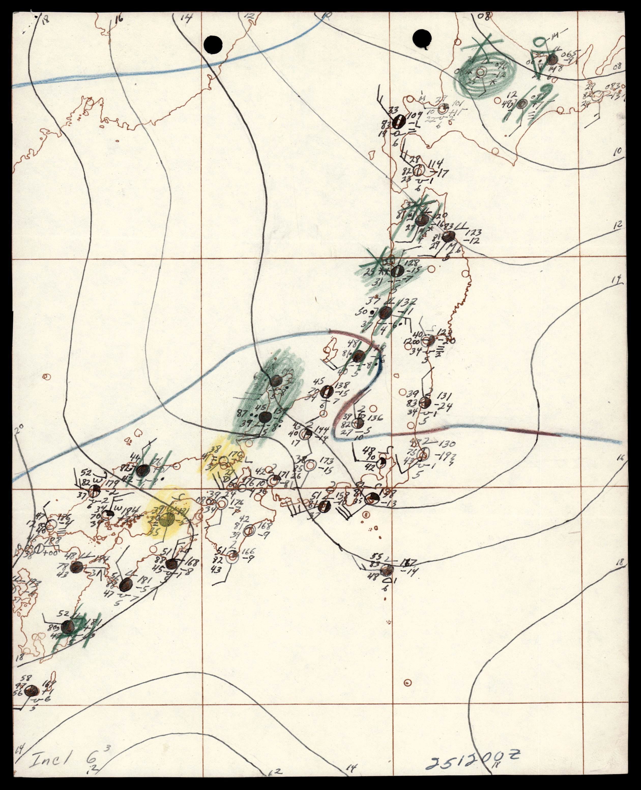
Hand-drawn surface synoptic weather chart for 25 January 1200Z over Japan.
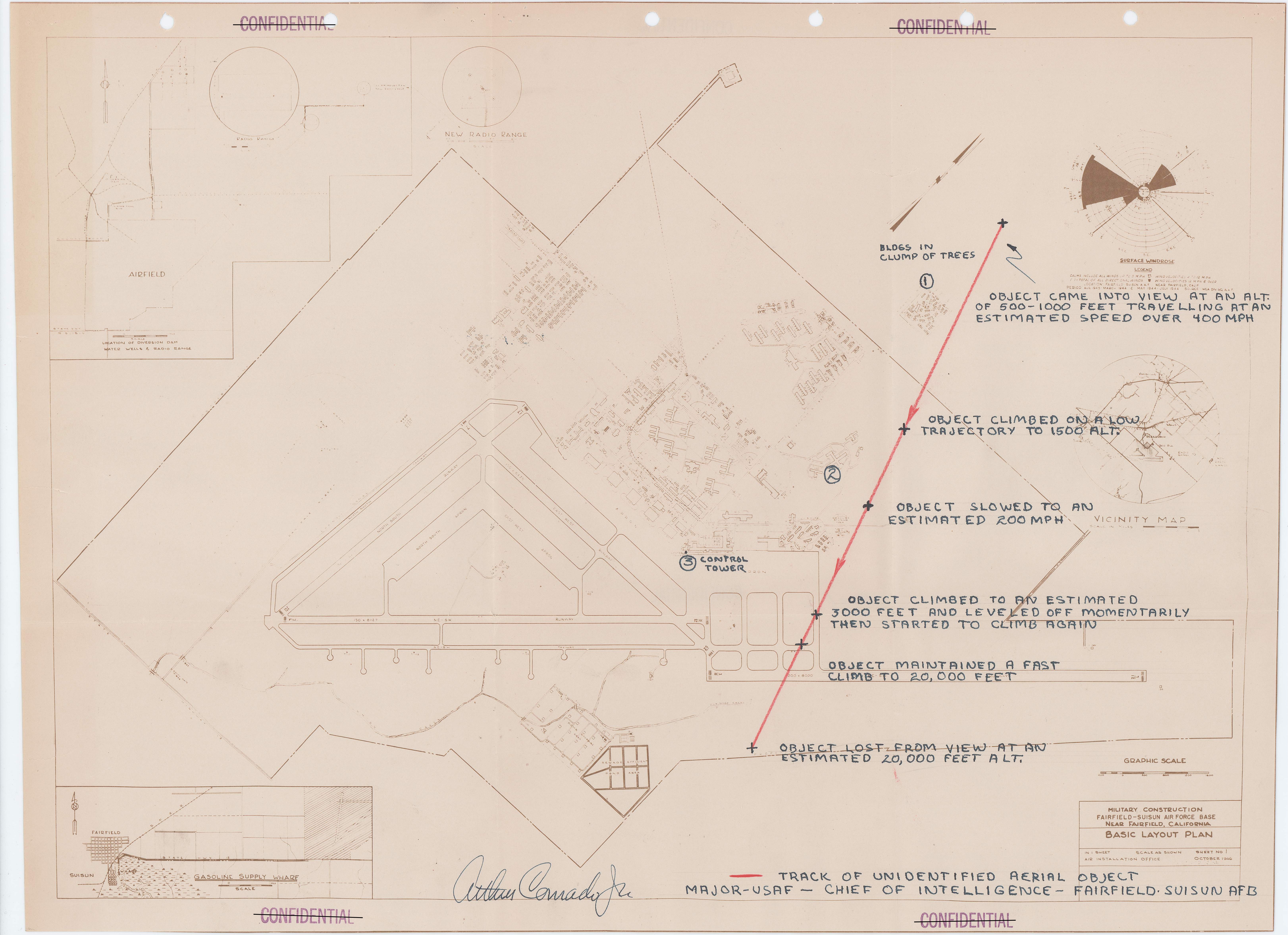
Annotated map of Fairfield-Suisun Air Force Base showing the flight path of an unidentified aerial object.
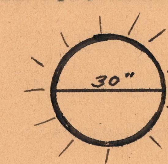
Sketch of a round light, labeled 30", with lines radiating outwards.
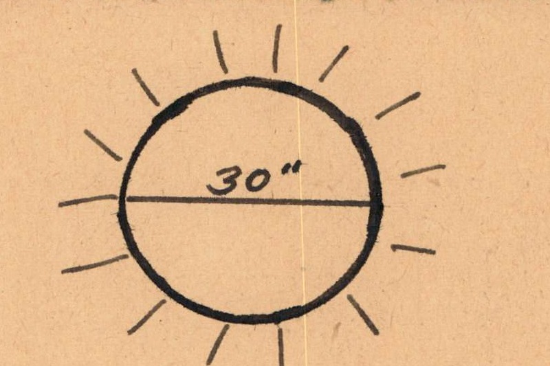
Sketch of a round light with rays emanating, labeled '30"'.
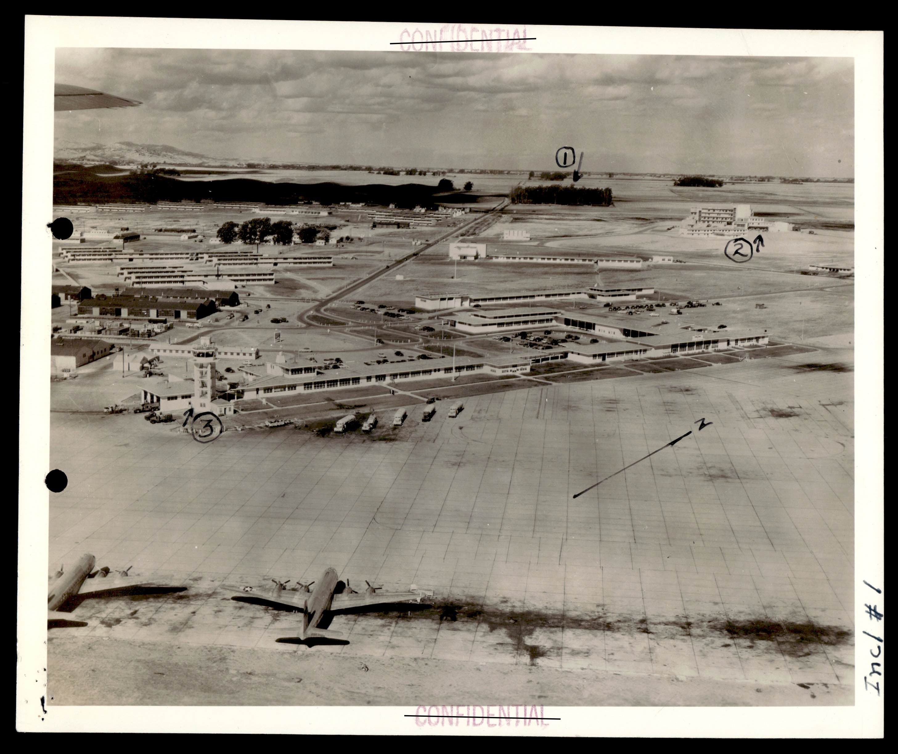
Aerial photograph of an airbase, likely Fairfield-Suisun Air Force Base, with annotations.
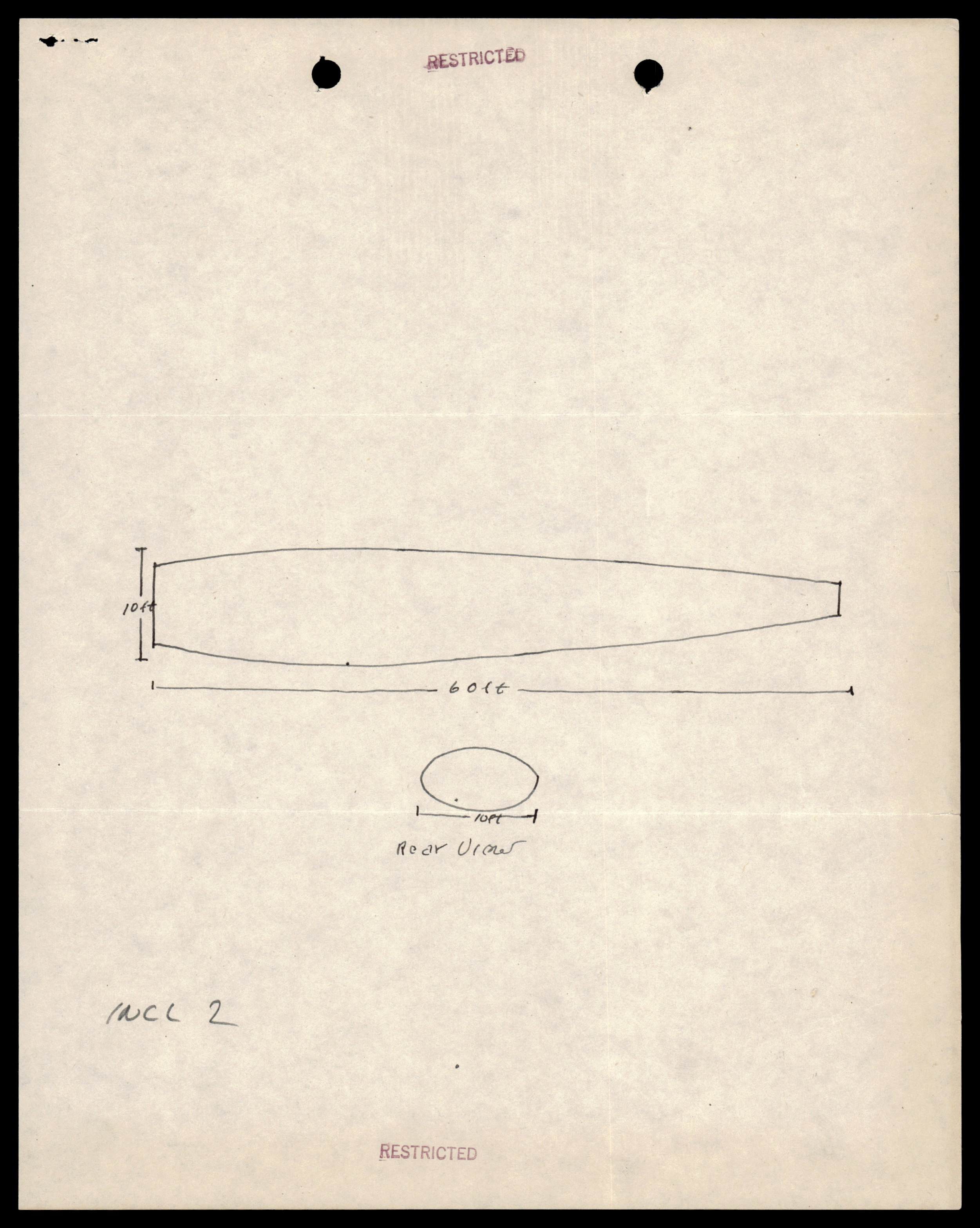
Sketch of a cigar-shaped object, 60 feet long and 10 feet in diameter, with a rear view.
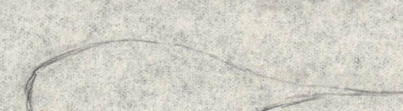
Sketch of an egg-shaped object with a tail.

US State Department seal
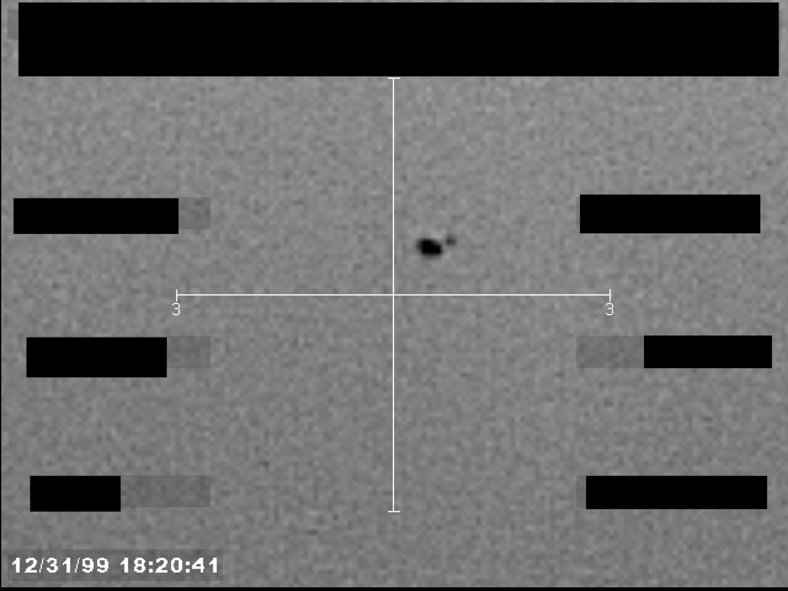
Sensor image, possibly infrared, showing a small, dark, irregularly shaped object at the center of a crosshair display. A timestamp is visible at the bottom left.
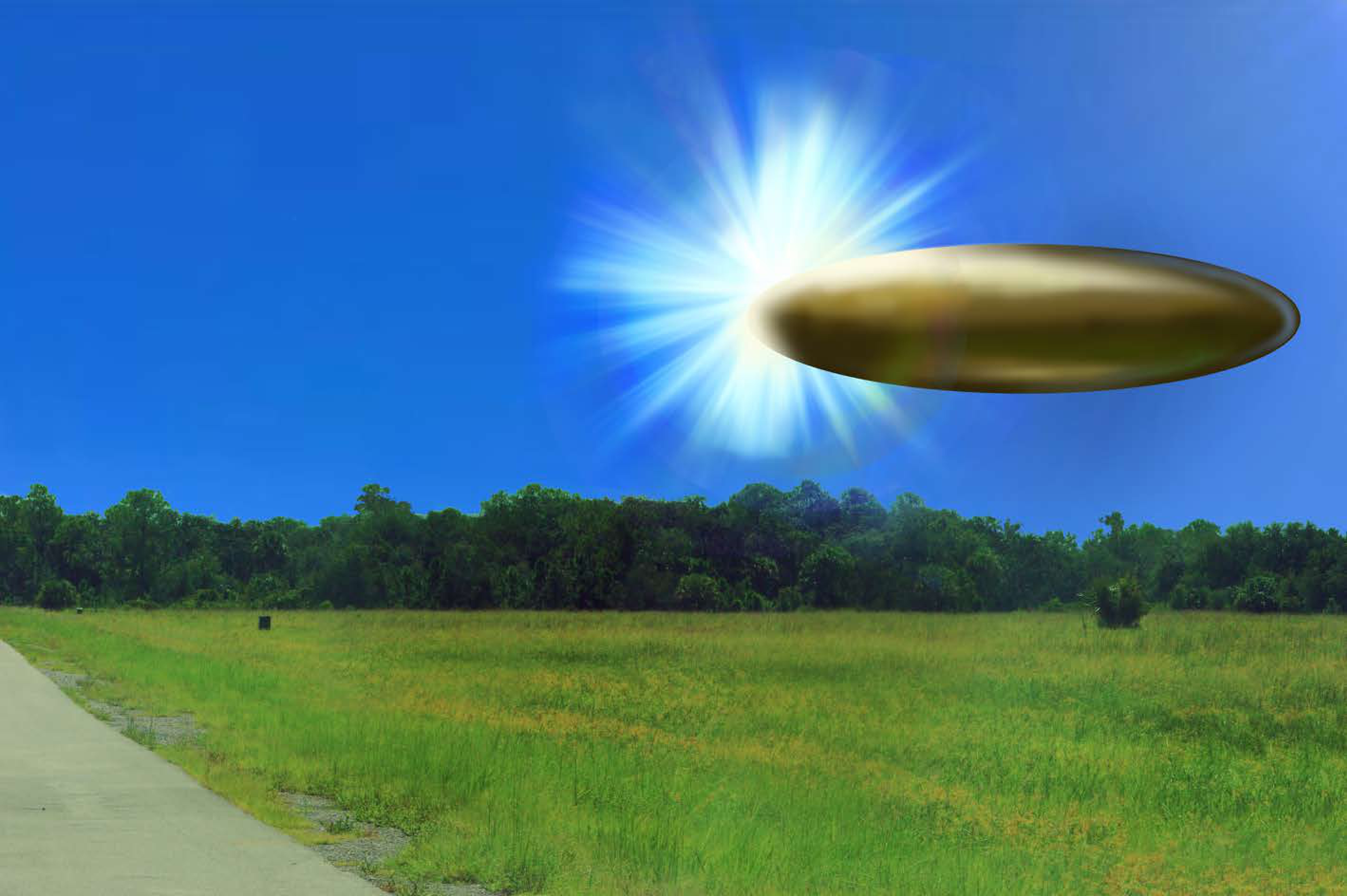
Composite image showing metallic disc-shaped object hovering over rural field with treeline and bright sunburst effect
This page appears to be a mirror image or bleed-through of the previous page's text. The text is reversed and illegible, except for a handwritten file number at the bottom.
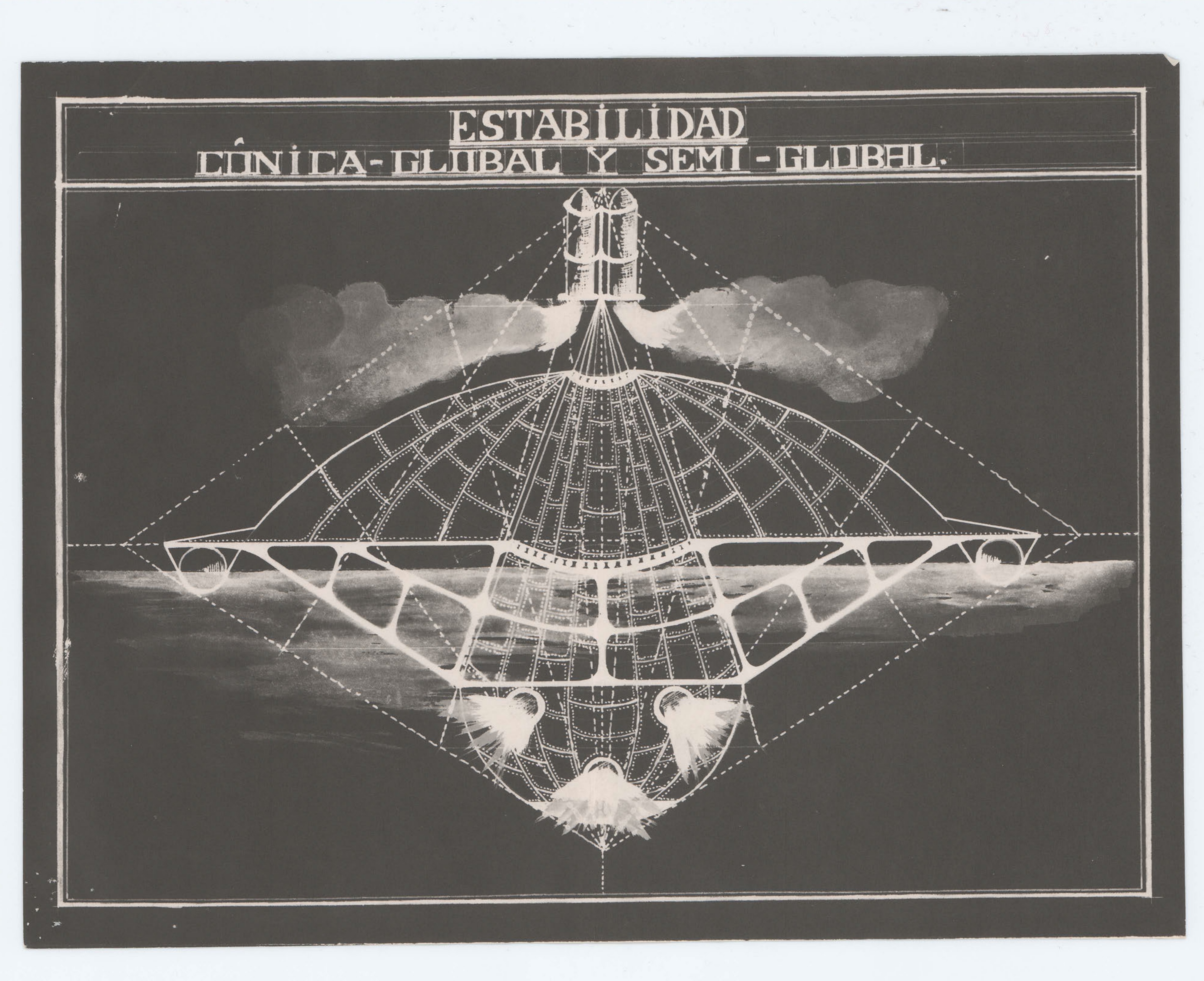
Diagram of a craft illustrating 'Conical-Global and Semi-Global Stability'.
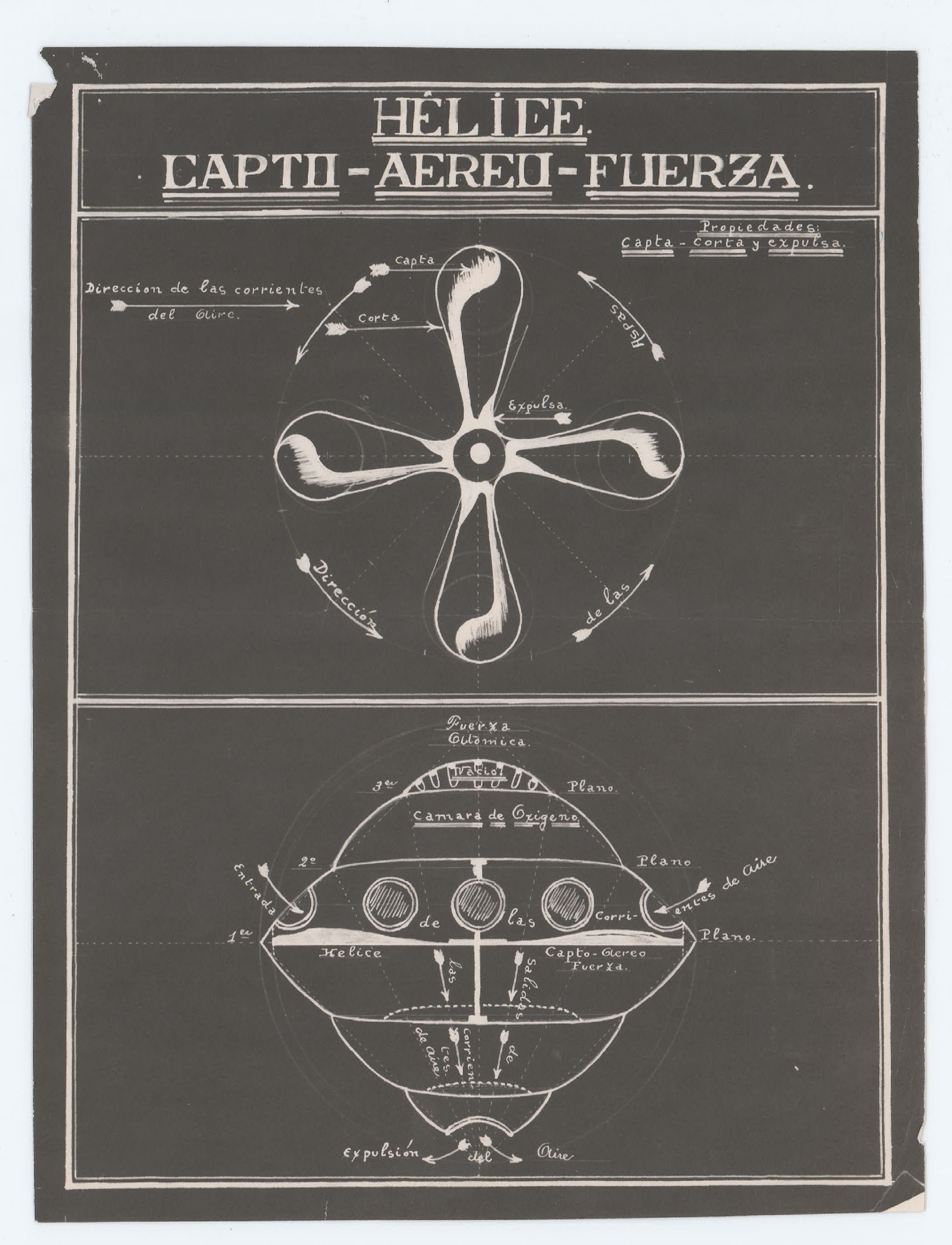
Diagram titled 'HELICE CAPTO-AEREO-FUERZA' showing propeller designs and a cross-section of a craft.
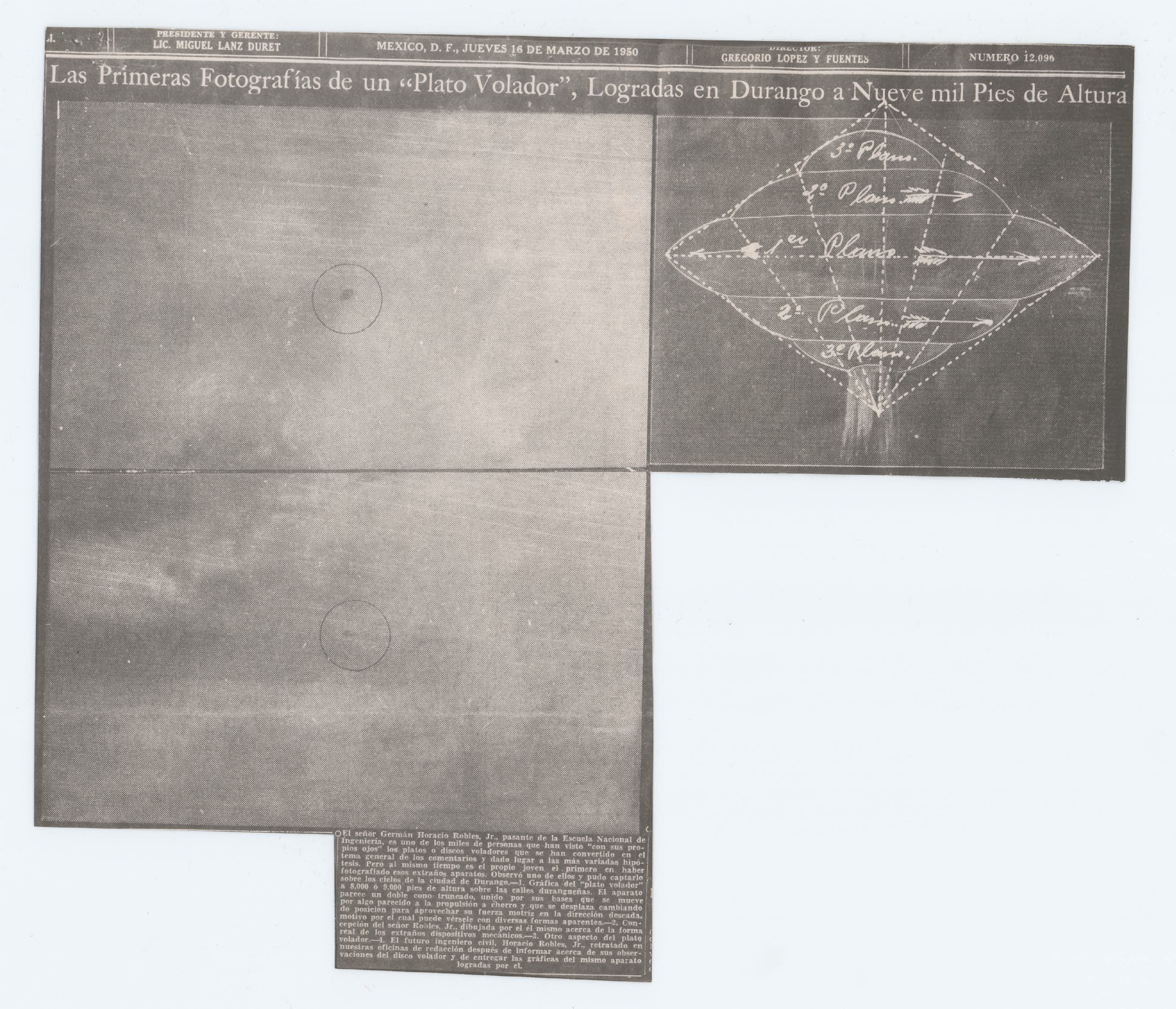
Photograph of a circular object in the sky, labeled '1'.
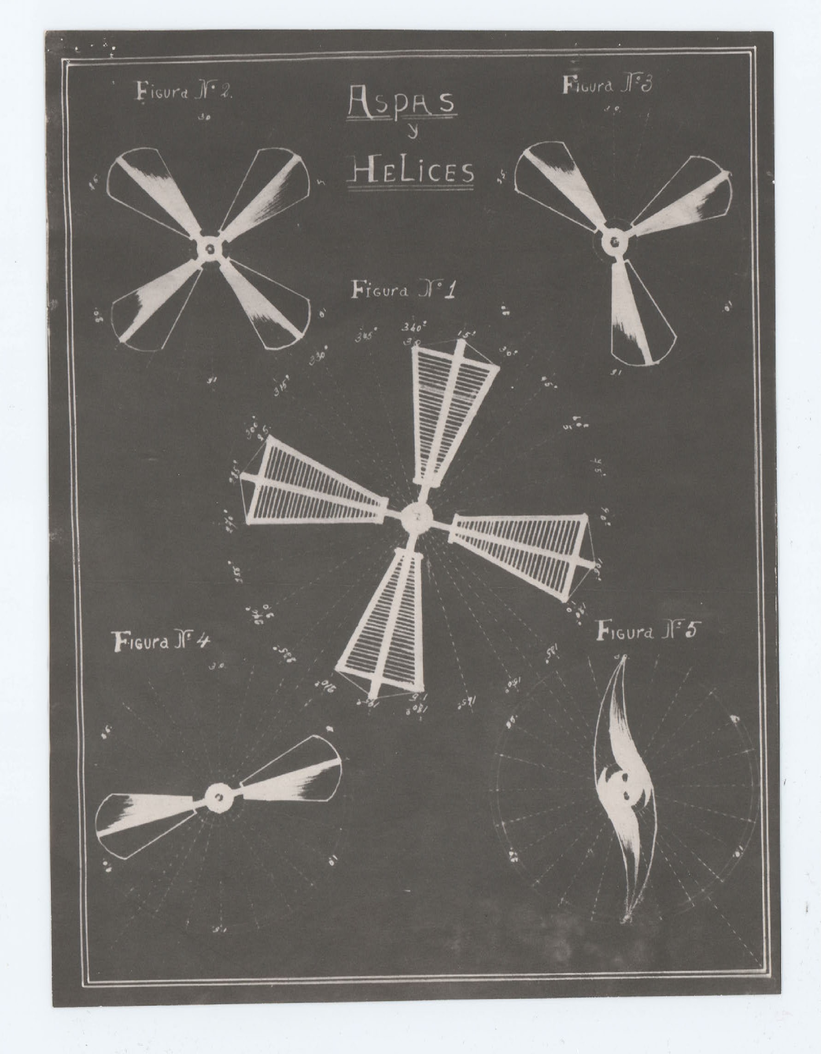
Diagram titled 'ASPAS y HELICES' showing five different propeller designs.
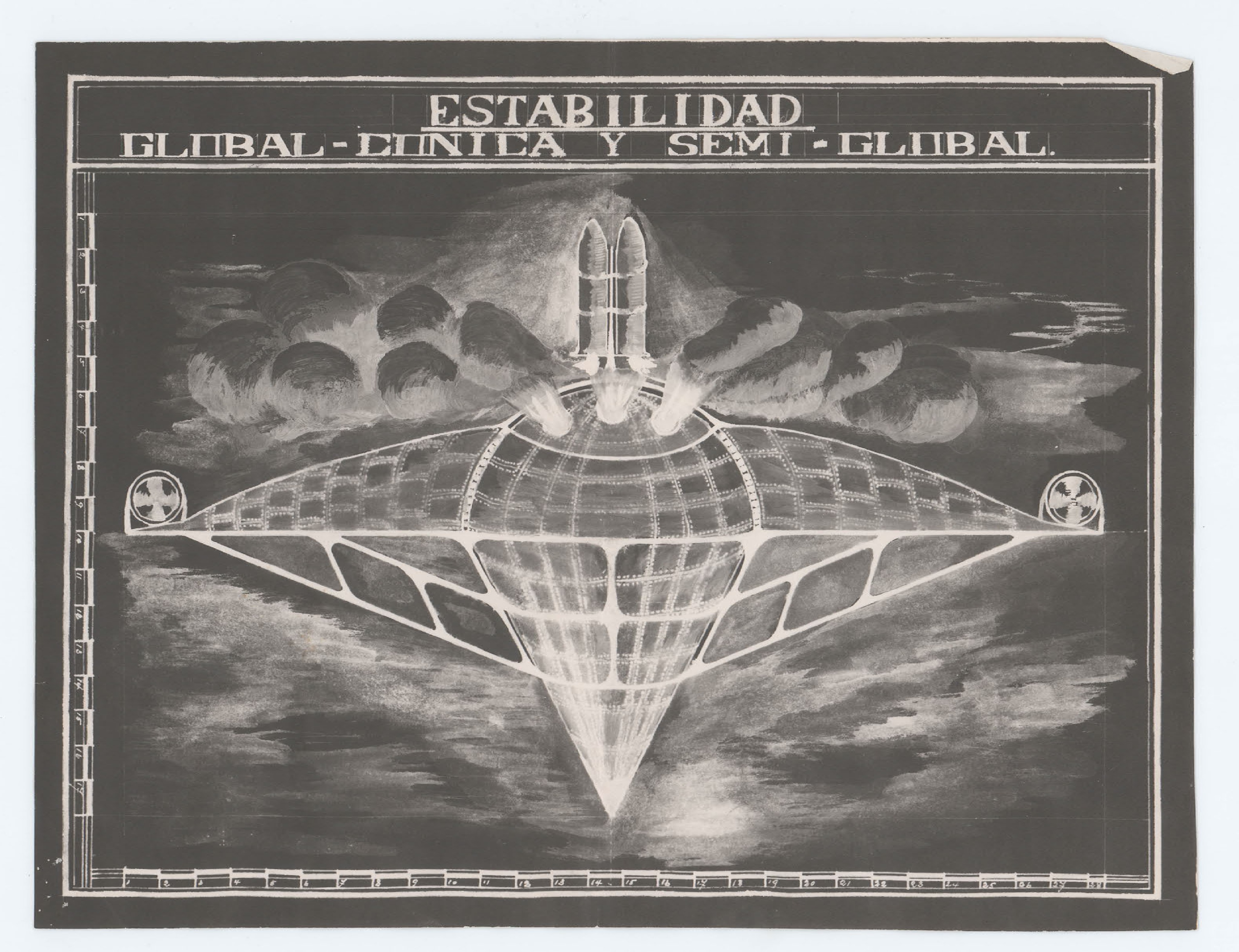
Diagram titled 'ESTABILIDAD GLOBAL-CONICA Y SEMI-GLOBAL' showing a craft design.
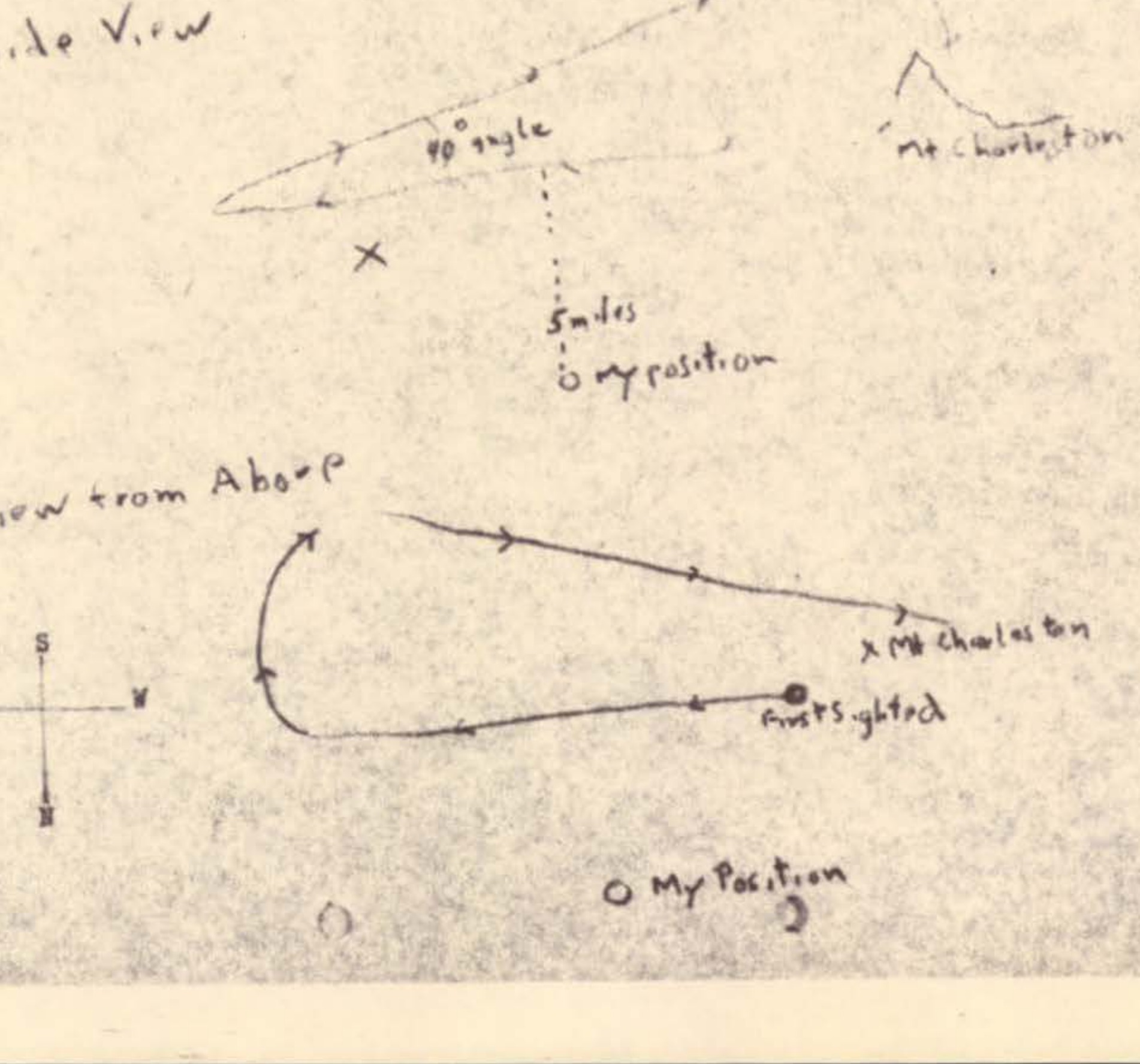
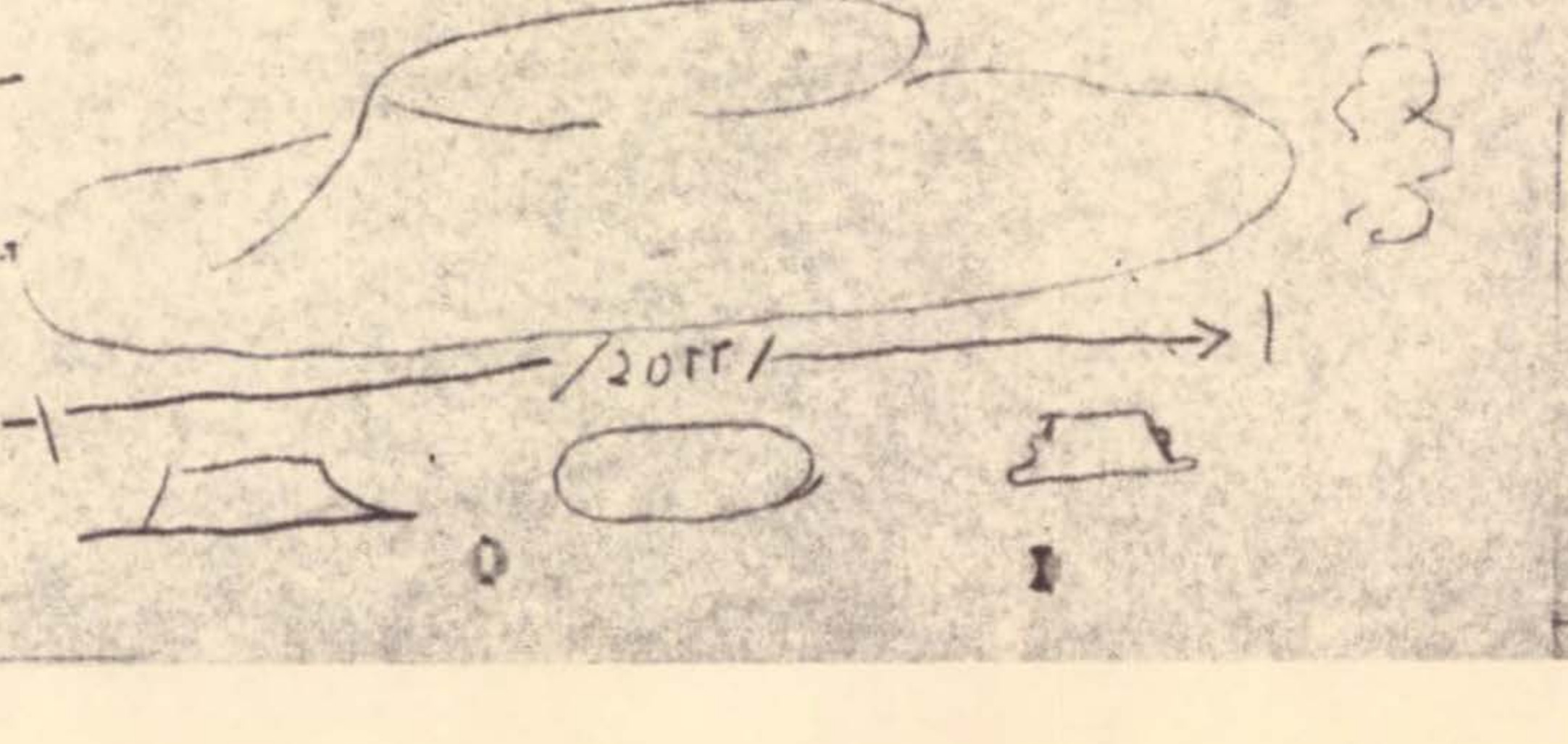
Hand-drawn diagrams showing side view and view from above of object trajectory with oscillation patterns and observer position
Hand-drawn diagram showing object trajectory with distance annotation of 20 ft
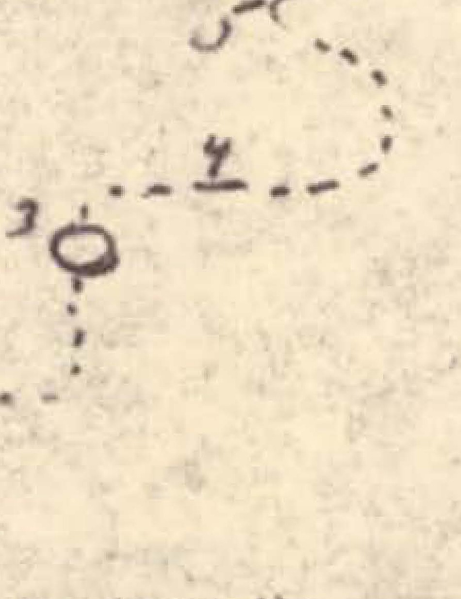
Hand-drawn diagram showing numbered positions 1-5 with dotted lines indicating object movement path
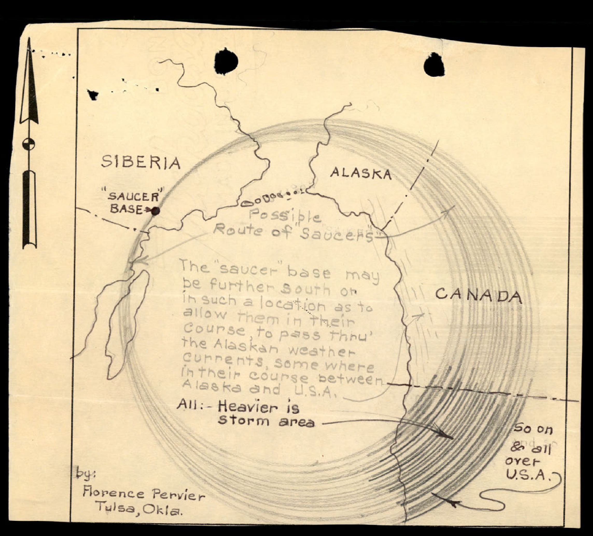
A hand-drawn map showing a possible route for 'saucers' from a base in Siberia, across Alaska, and into the U.S.A. and Canada.
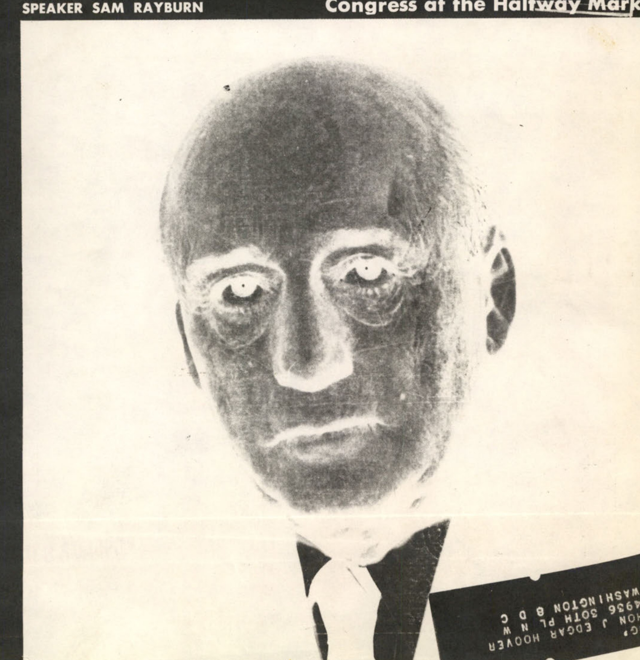
A negative image of Speaker Sam Rayburn.
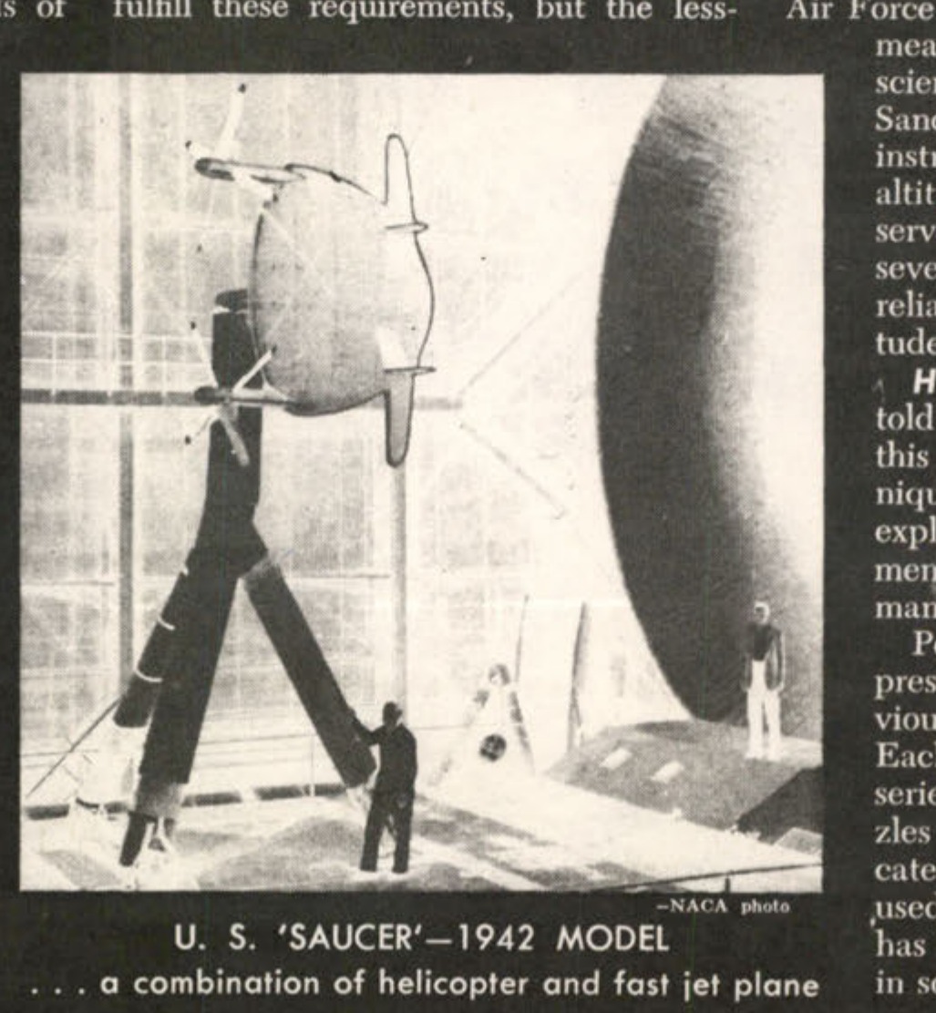
U. S. 'SAUCER'-1942 MODEL .. a combination of helicopter and fast jet plane
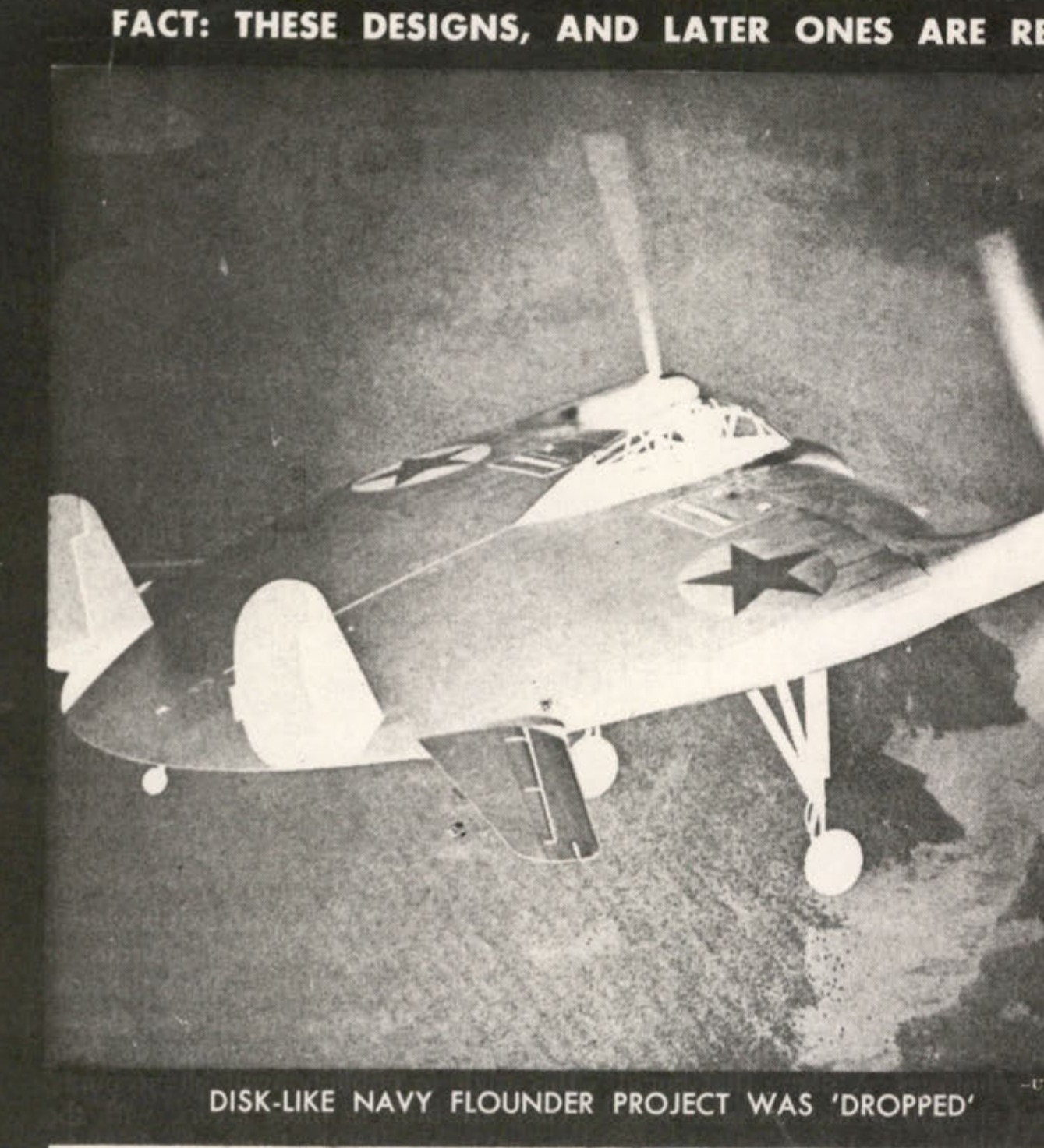
DISK-LIKE NAVY FLOUNDER PROJECT WAS 'DROPPED'
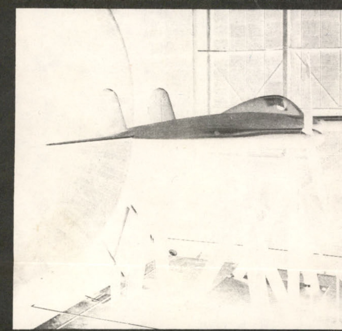
MOCK-UP OF EARLY MODEL IS TESTED IN WIND TUNNEL
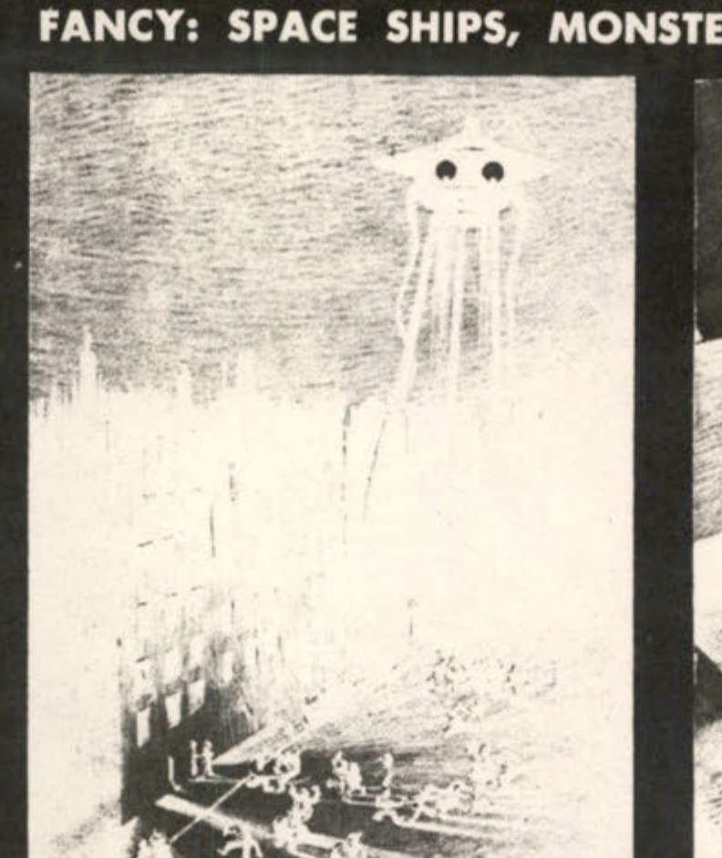
NOCTURNAL 'INVASION'
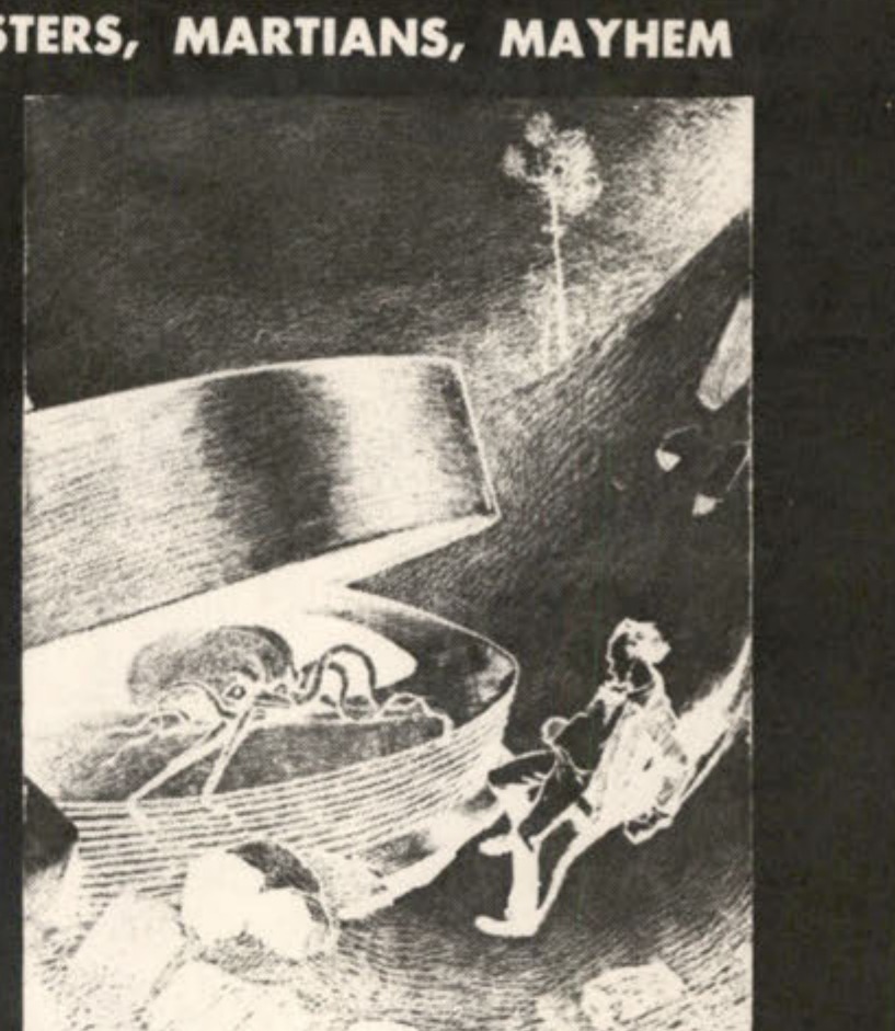
SURPRISE PACKAGE FROM MARS
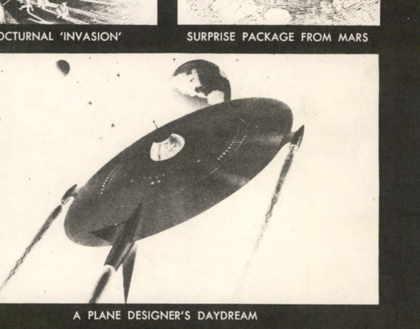
A PLANE DESIGNER'S DAYDREAM
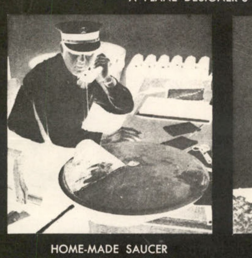
HOME-MADE SAUCER
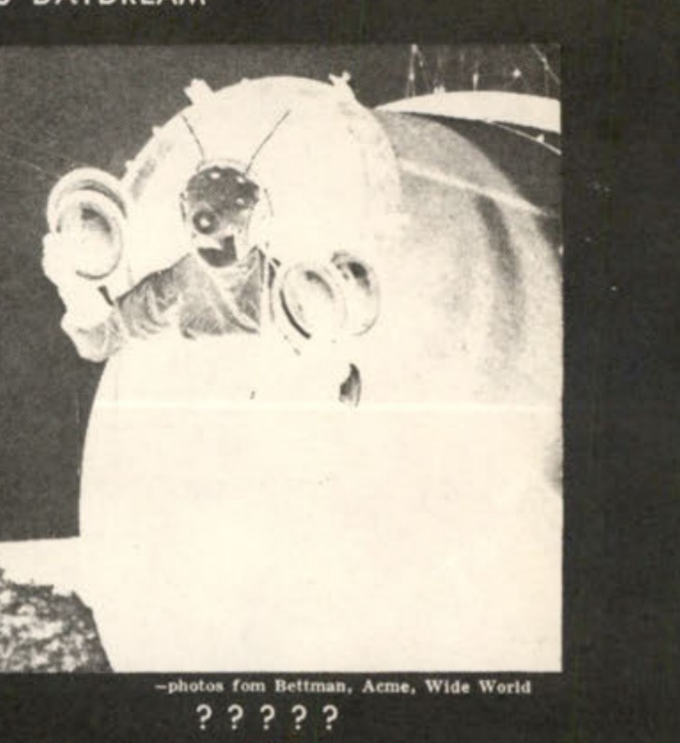
?????
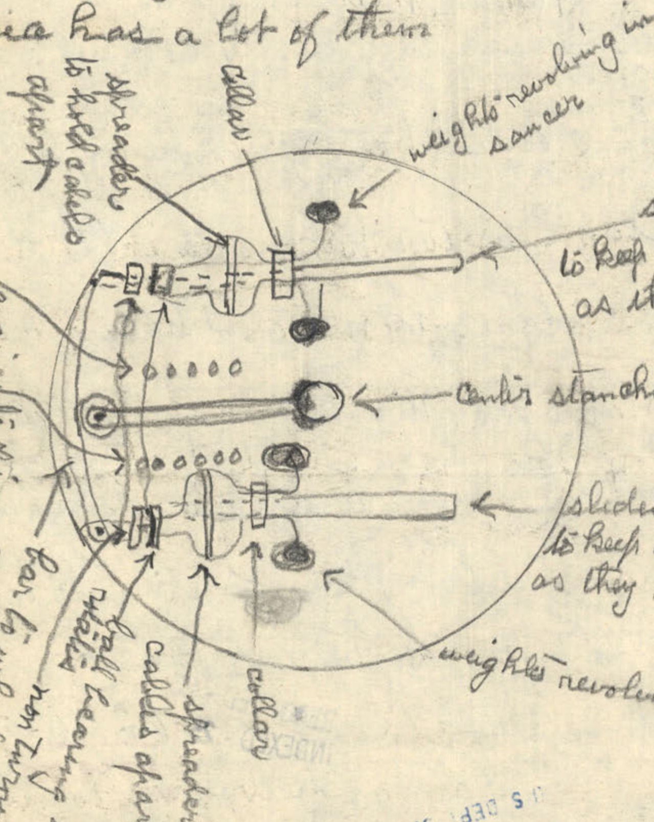
A diagram showing the internal mechanism of a saucer, with weights, cables, and a central stanchion.
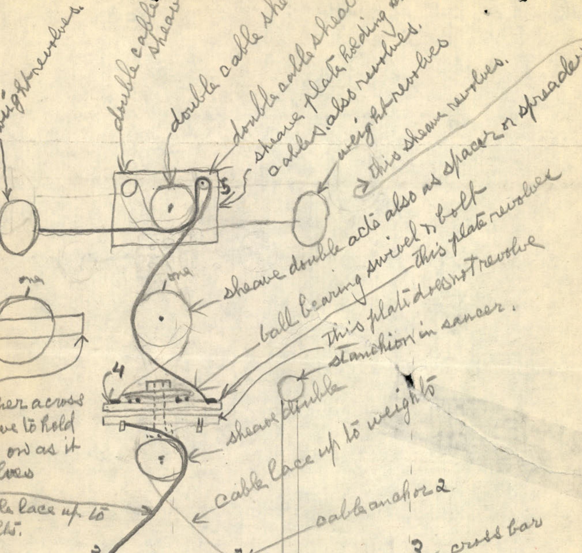
A series of diagrams showing the arrangement of cables, sheaves, and weights in the saucer's mechanism.
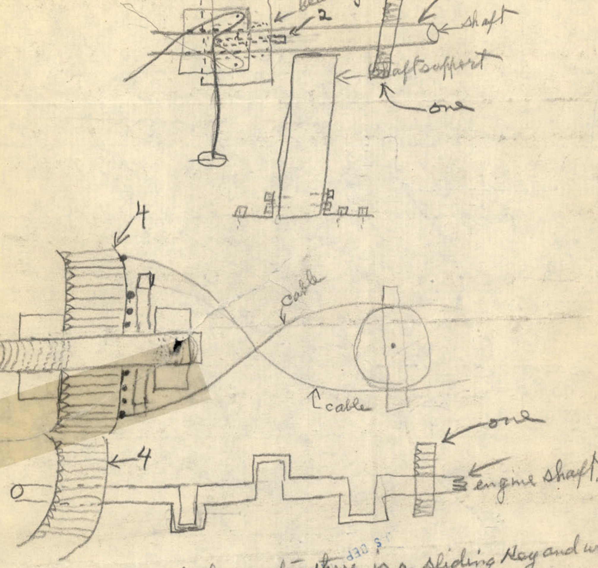
Diagrams showing cog wheels, shafts, and bearings as part of the saucer's propulsion mechanism.
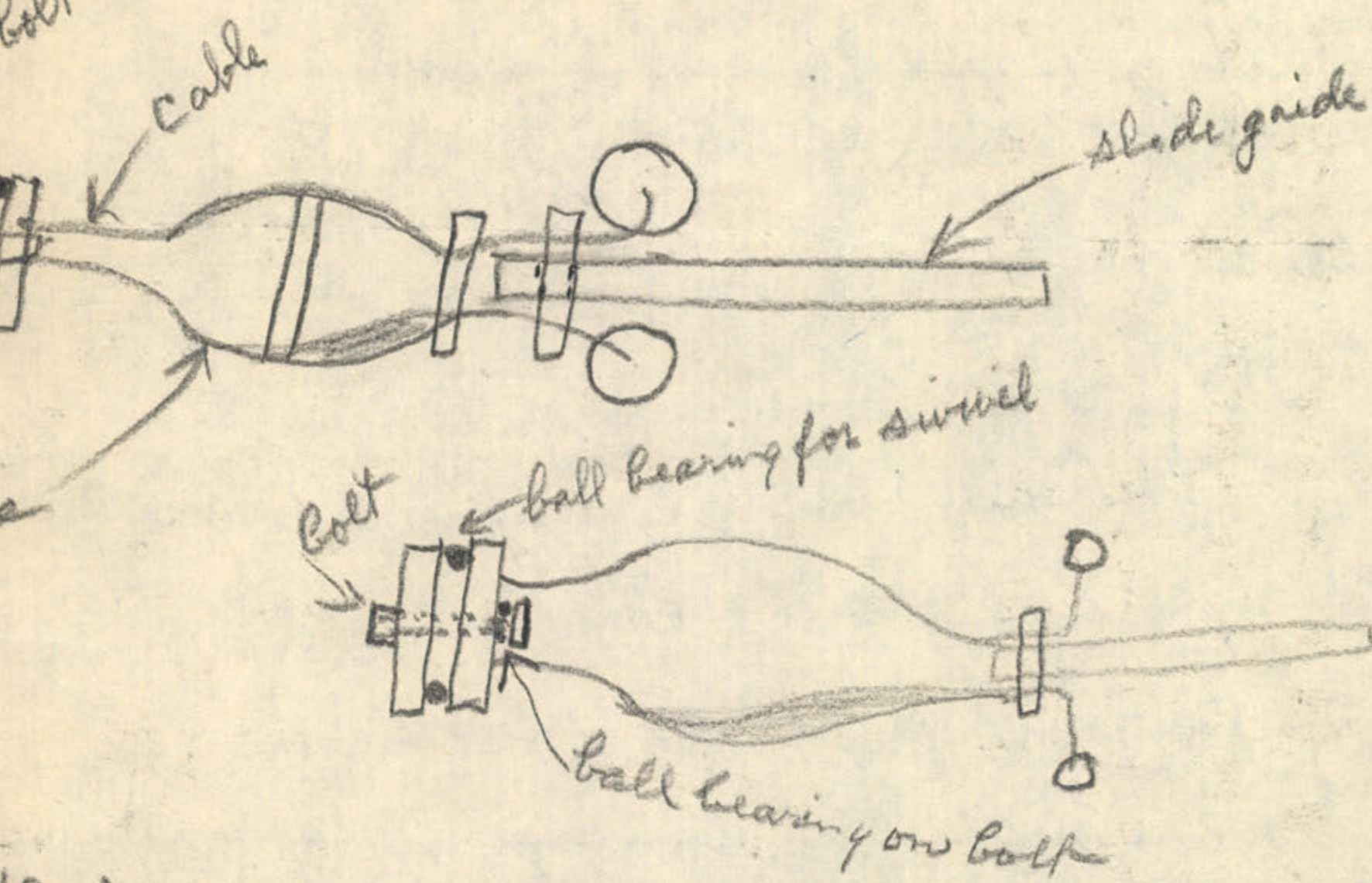
Two diagrams showing a side view of the saucer, possibly illustrating the launch mechanism.
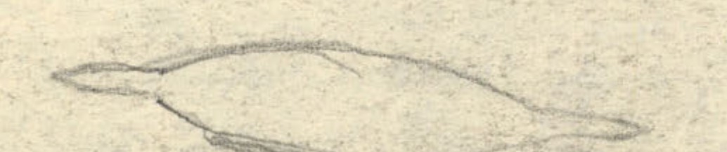
A small sketch of the saucer's side profile.
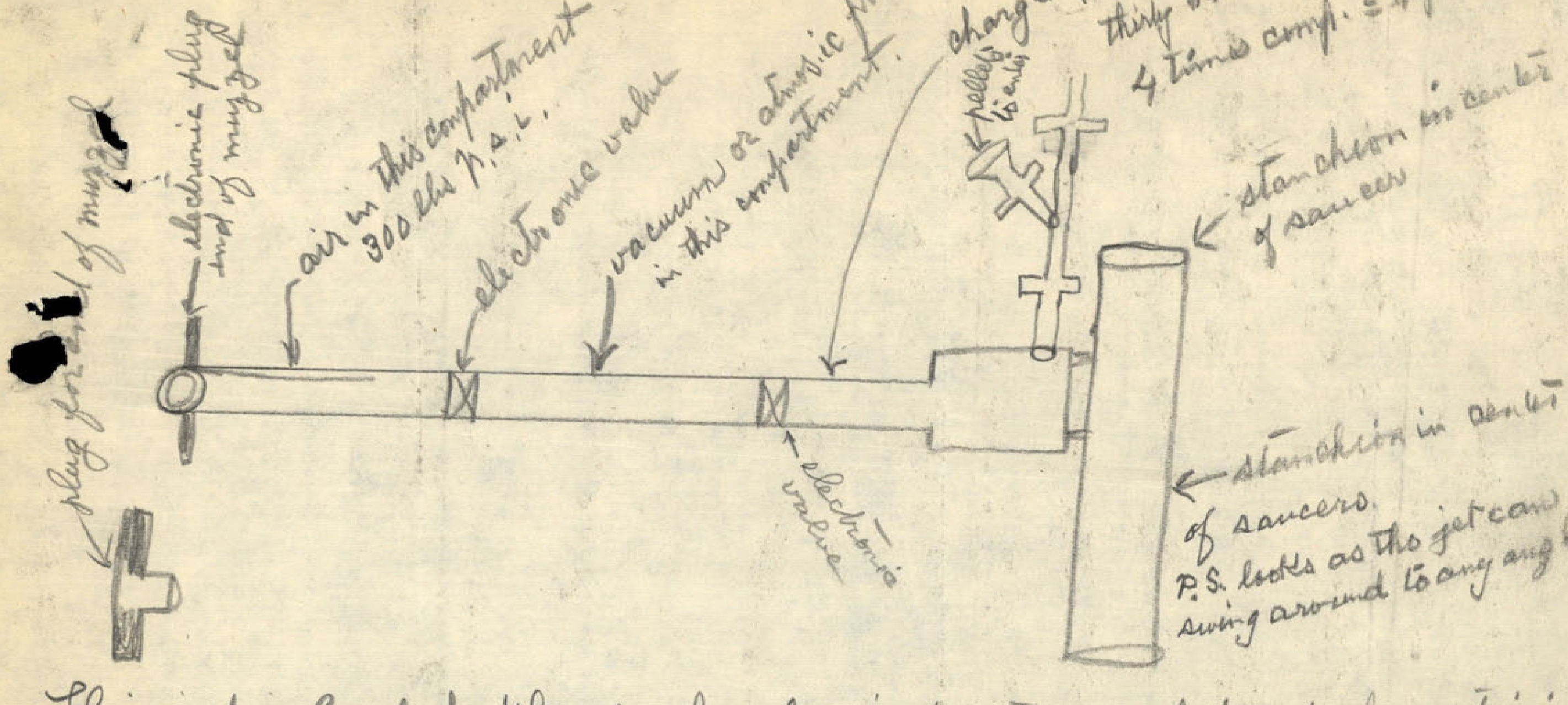
A detailed diagram of the jet propulsion system for the saucer.
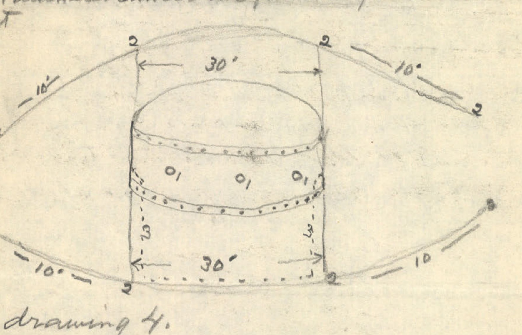
A diagram showing a cross-section of the saucer, with dimensions and labels.
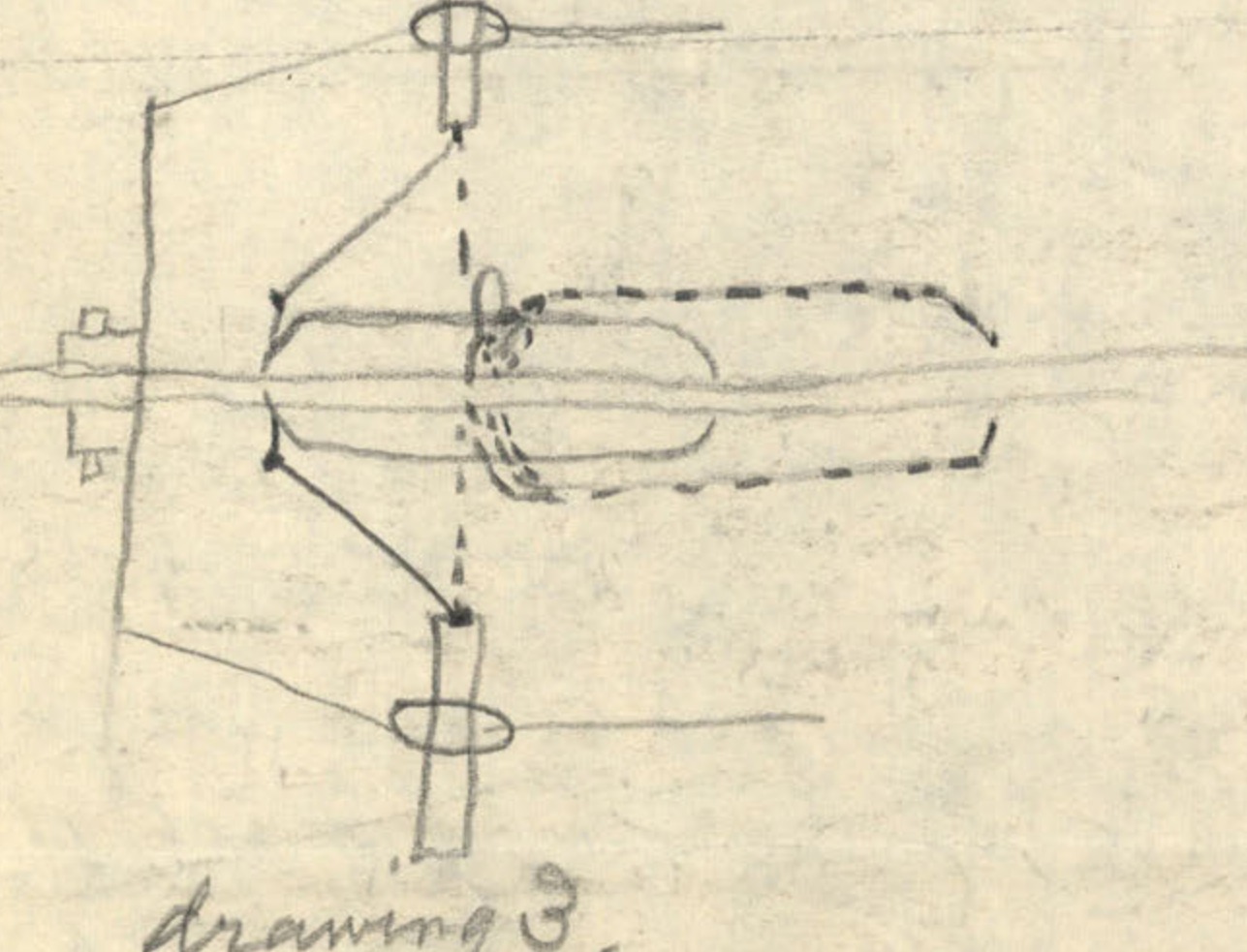
A diagram labeled 'drawing 3' showing a mechanical assembly, possibly related to the centrifugal force mechanism.
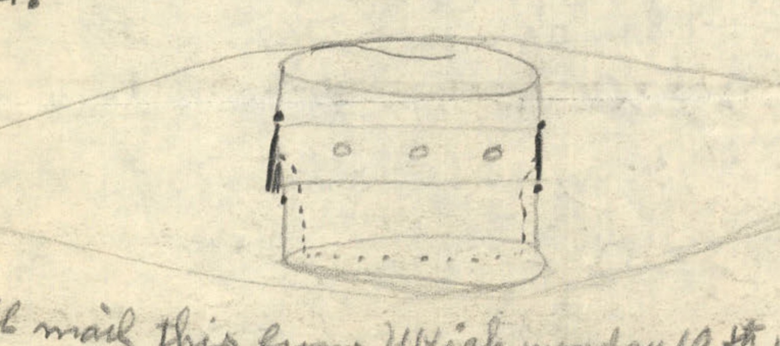
A sketch showing the side profile of the saucer.
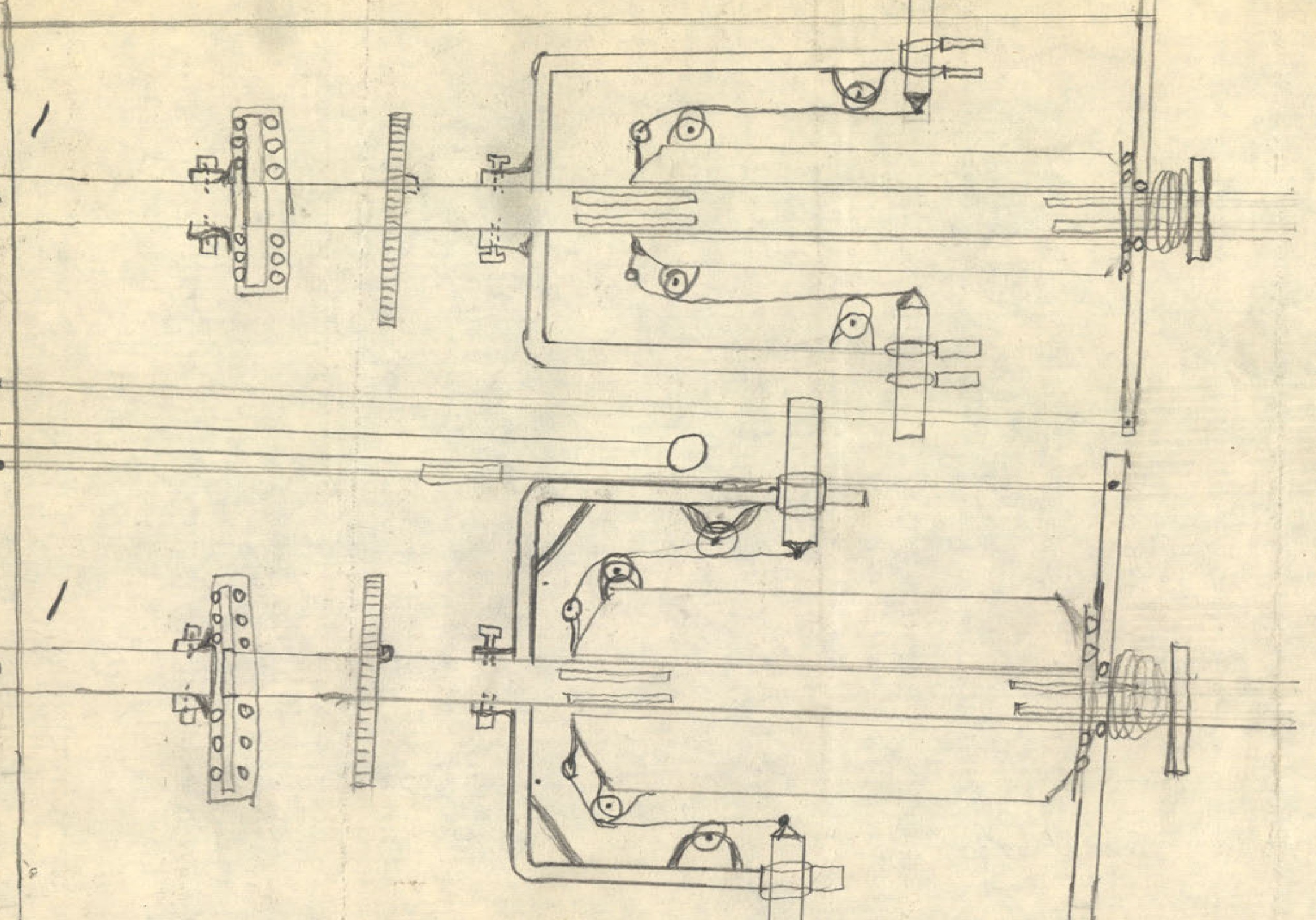
A detailed mechanical diagram labeled 'Drawing #1'.
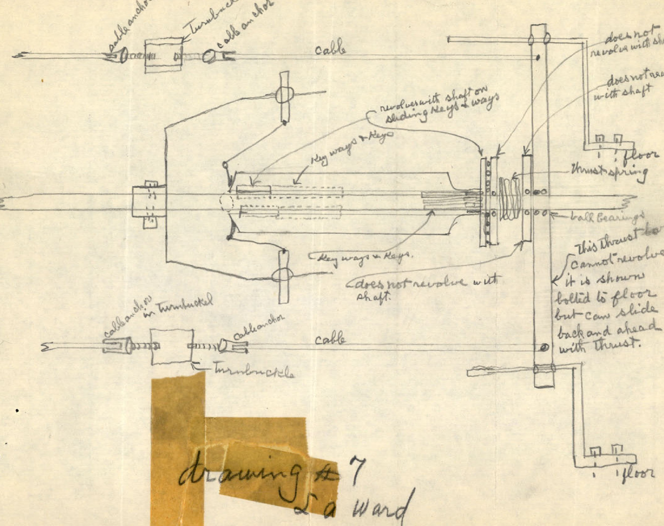
A detailed mechanical diagram labeled 'drawing #7' showing shafts, bearings, and cables.
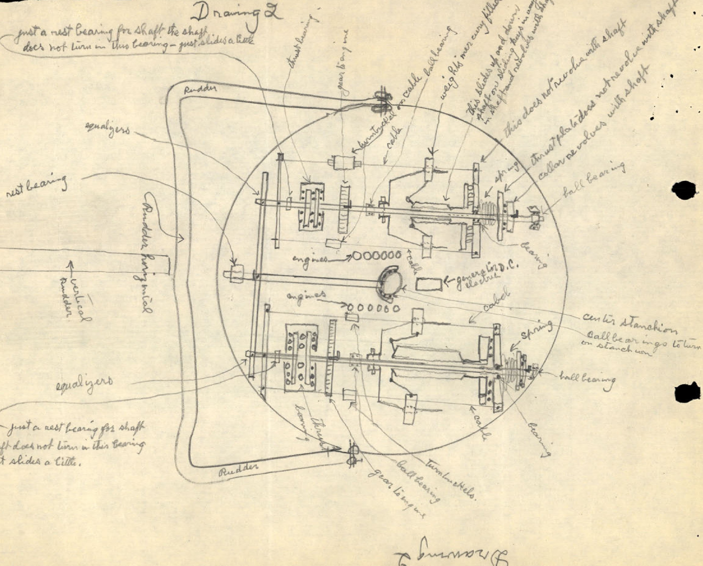
A large, detailed diagram labeled 'Drawing 2' showing a top-down view of the saucer's internal mechanisms, including engines, rudders, and the centrifugal weight system.
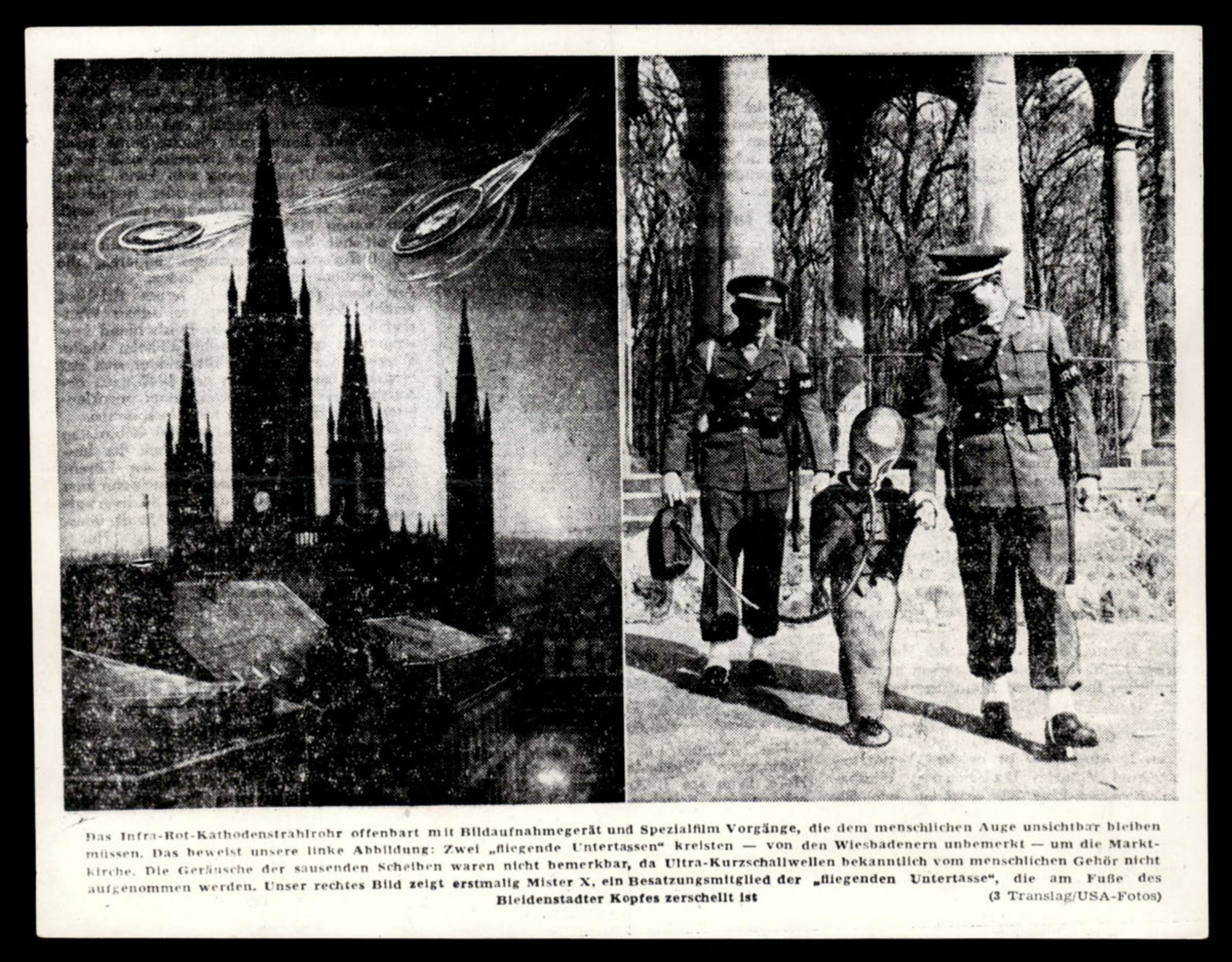
Composite image showing two UFOs over a church (left) and two military police escorting a small figure in a helmet (right).
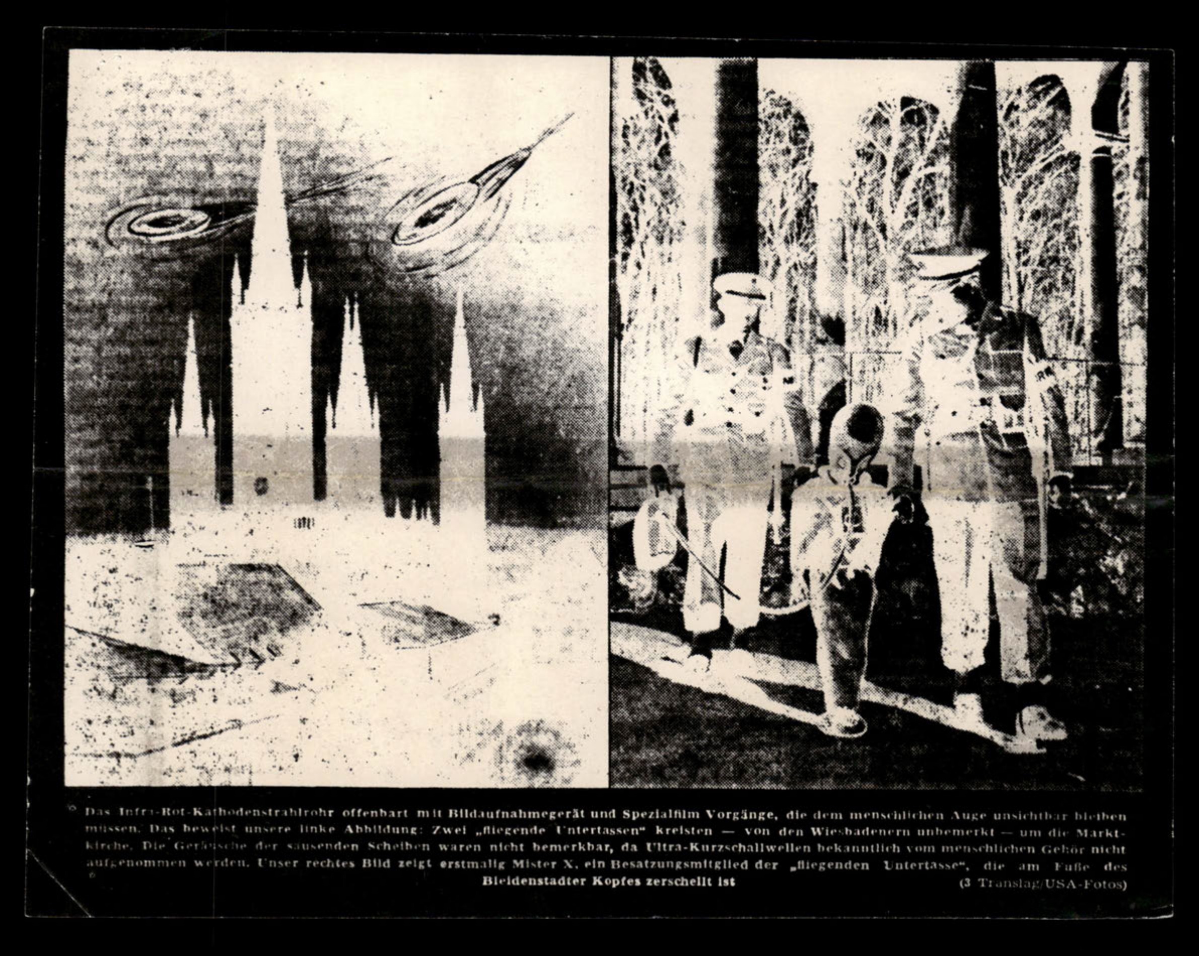
Negative image of the composite photograph from the previous page.
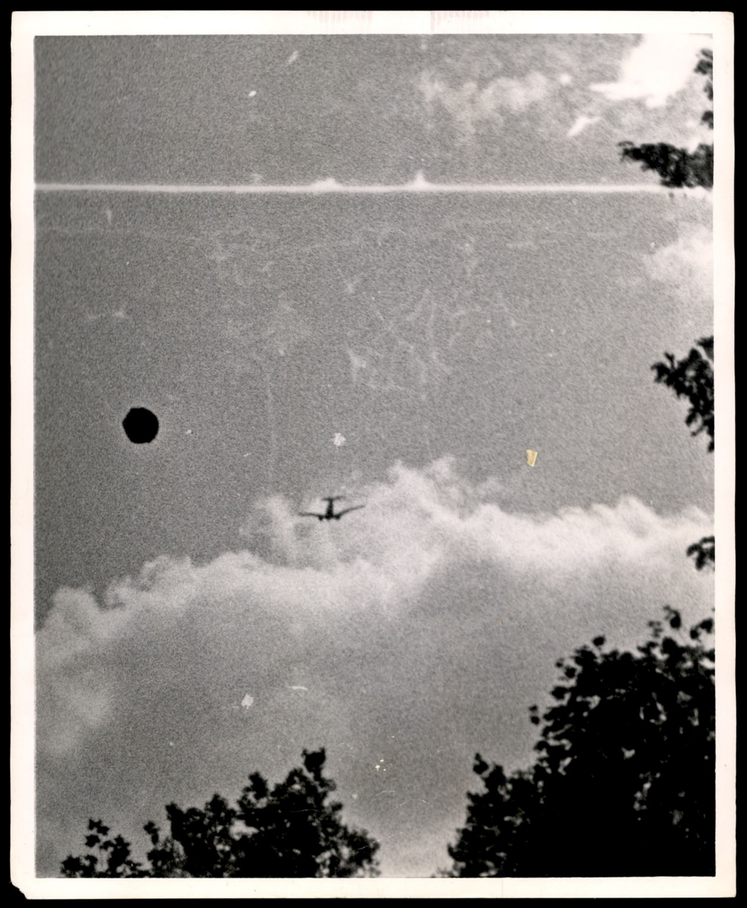
Photograph of a dark circular object and a conventional aircraft in a cloudy sky.
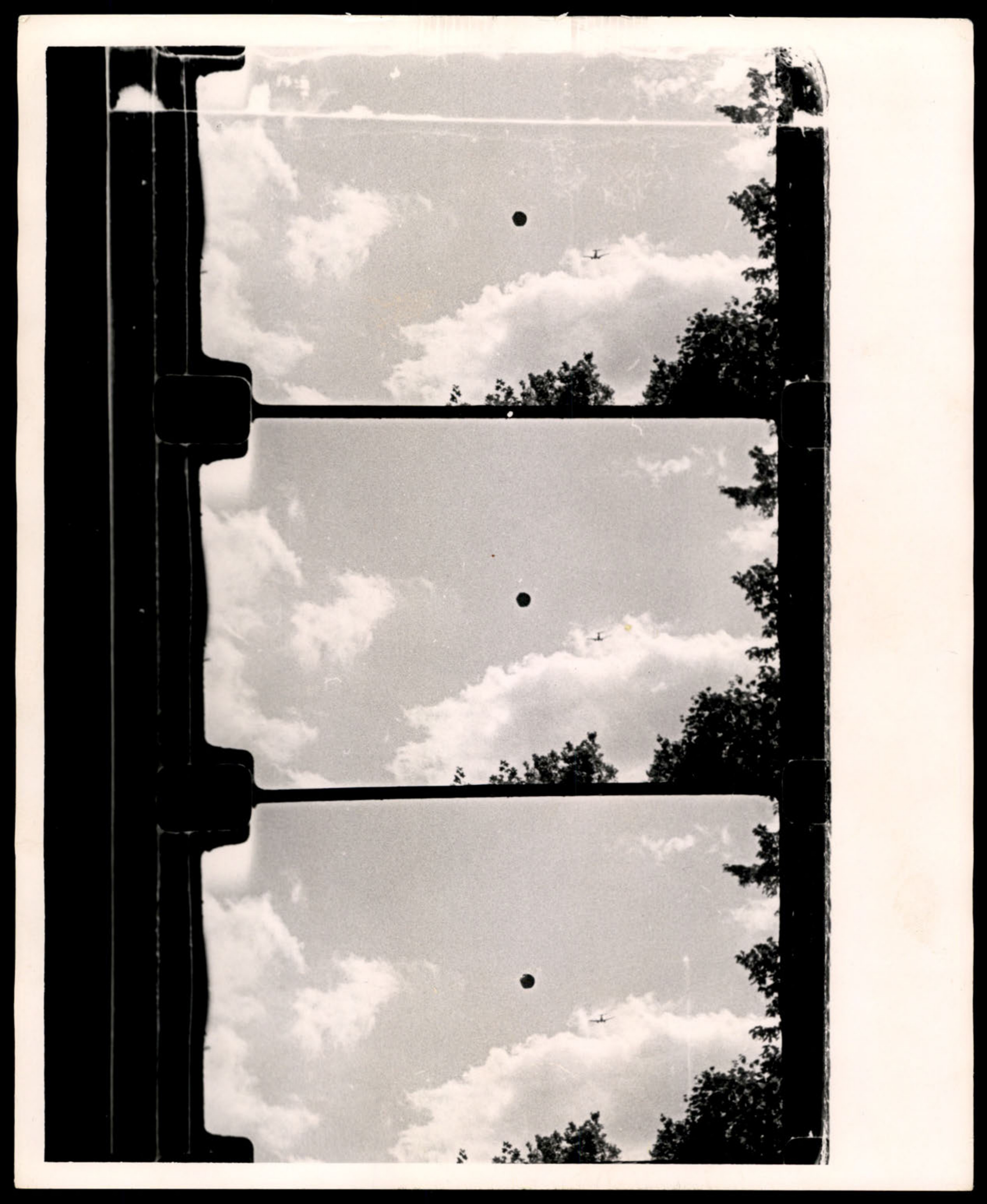
Three consecutive frames from a film strip showing a dark circular object and a conventional aircraft.
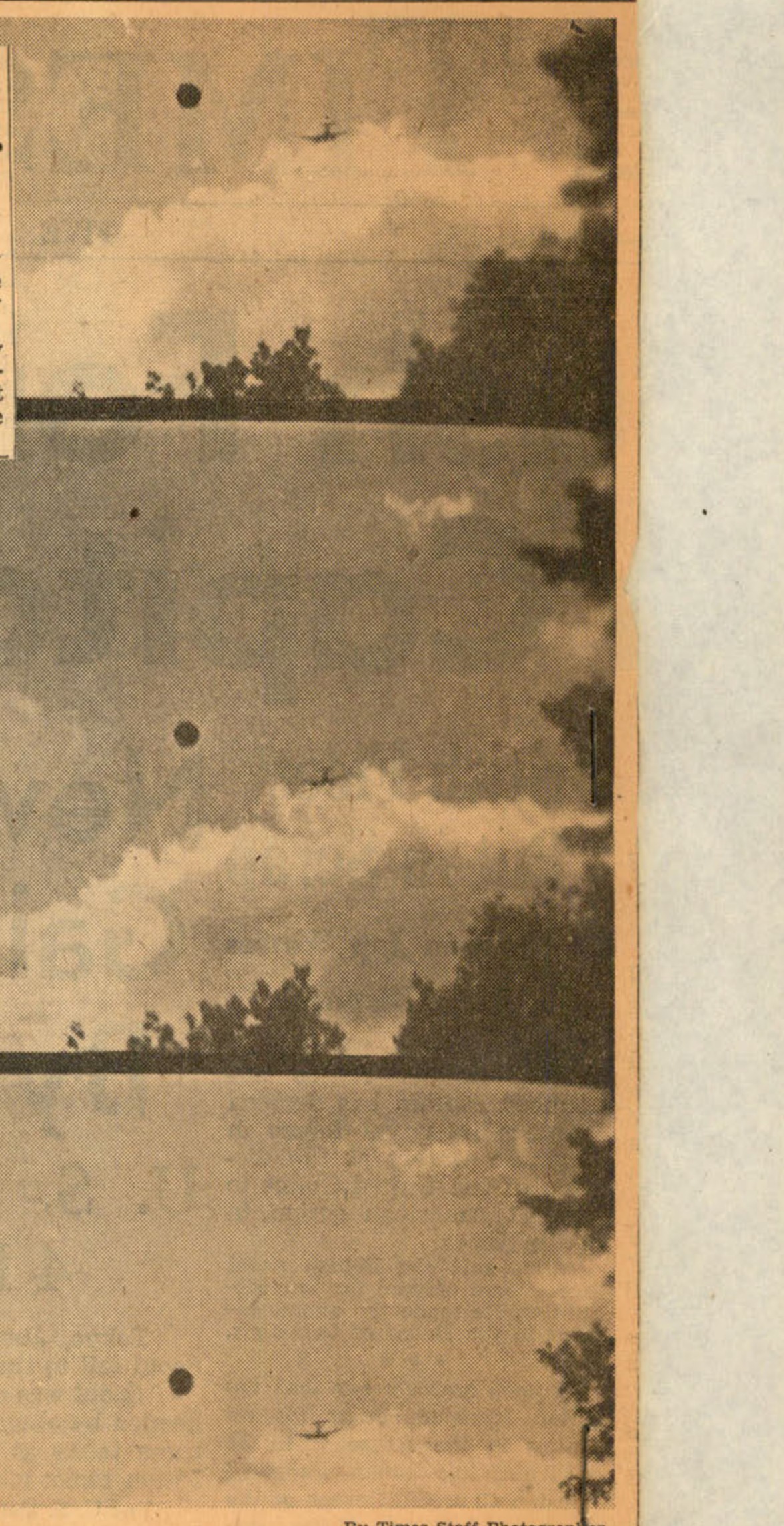
Three frames from a film showing a dark object in the sky.
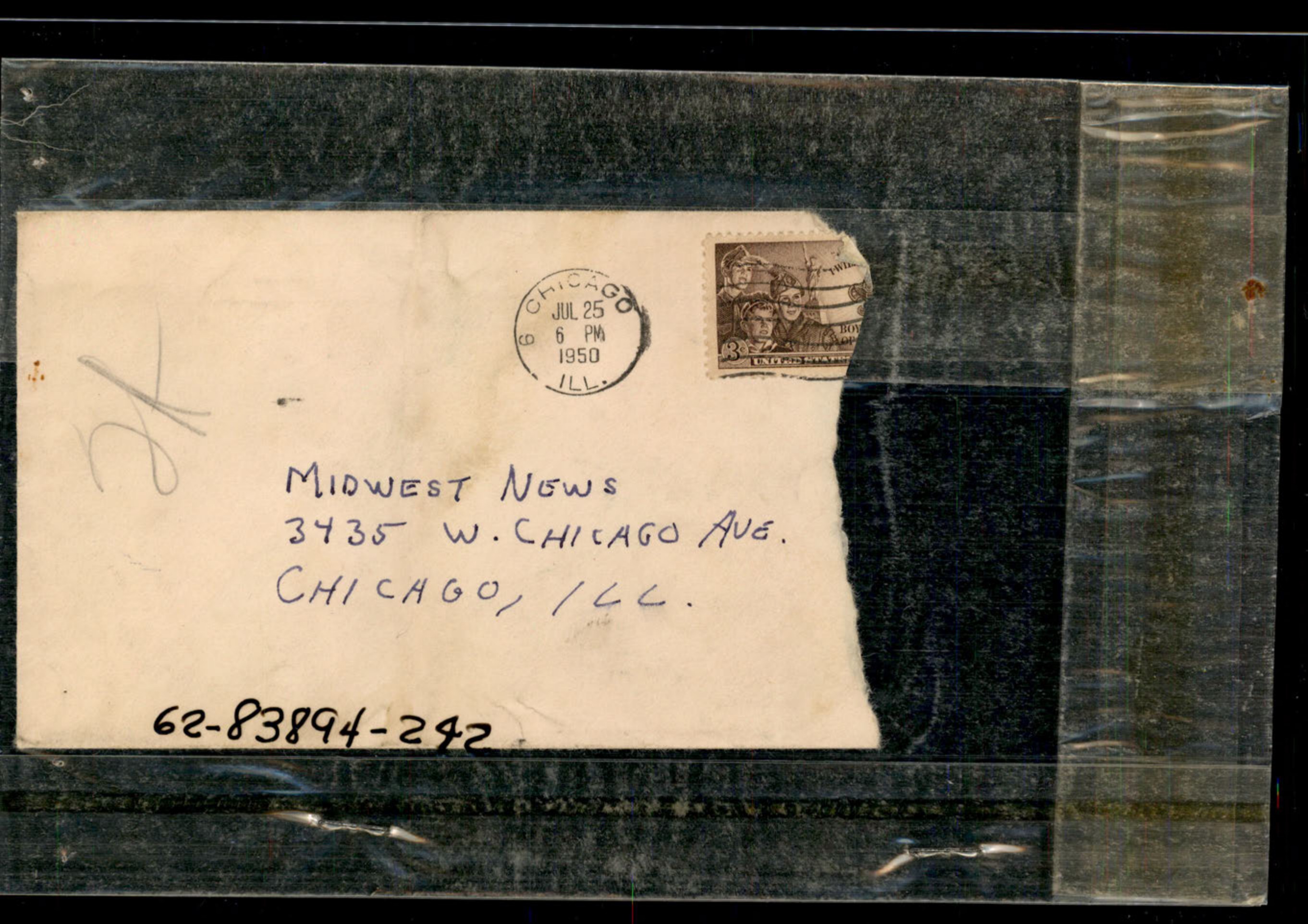
Photograph of an envelope addressed to Midwest News.
Photograph of the back of an envelope.
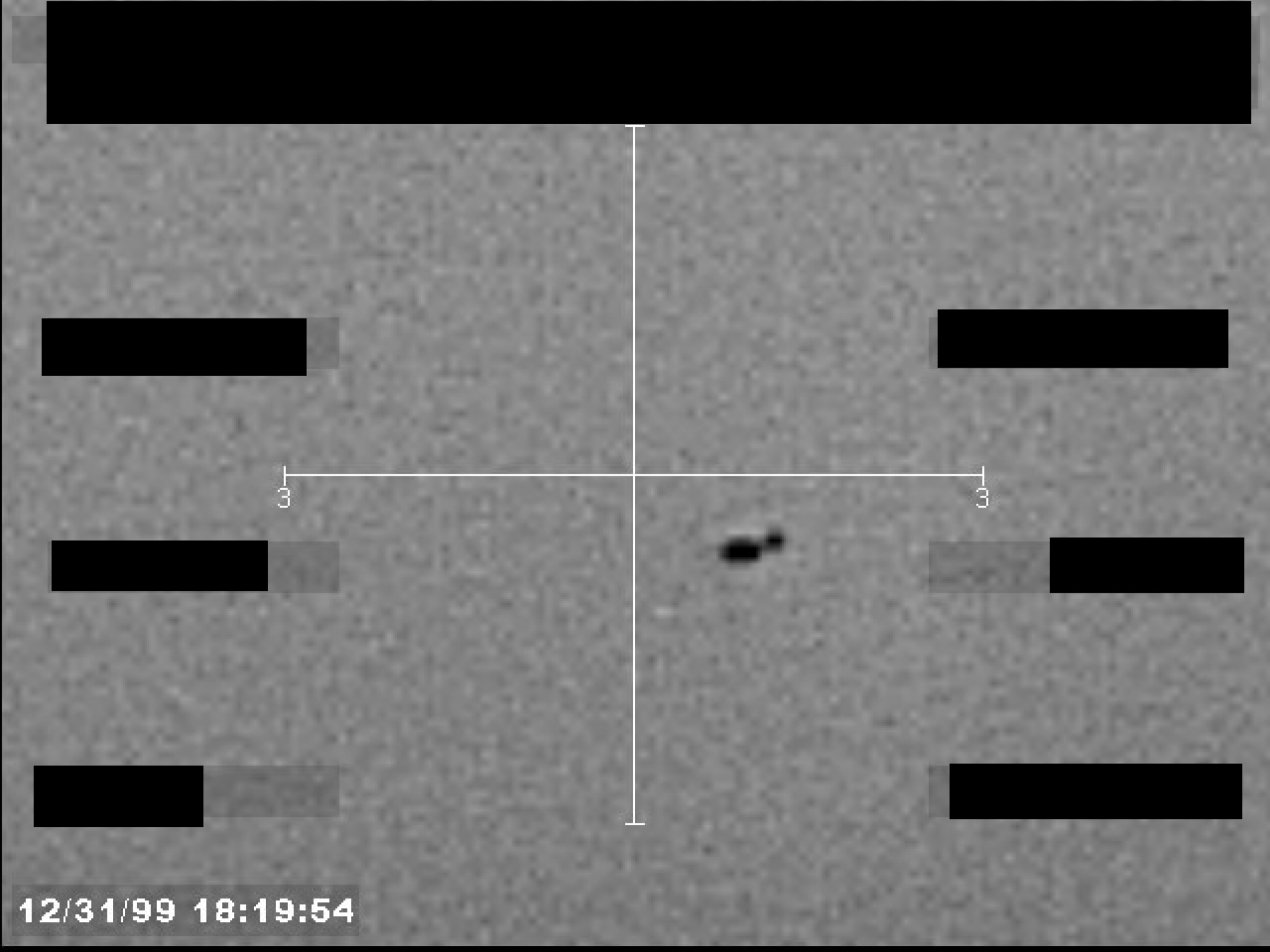
Sensor footage showing a small, dark, unidentified object near a central crosshair, with a timestamp of 12/31/99 18:19:54.
A grainy, black-and-white image from a sensor or camera, showing a small, dark object at the center of crosshairs.
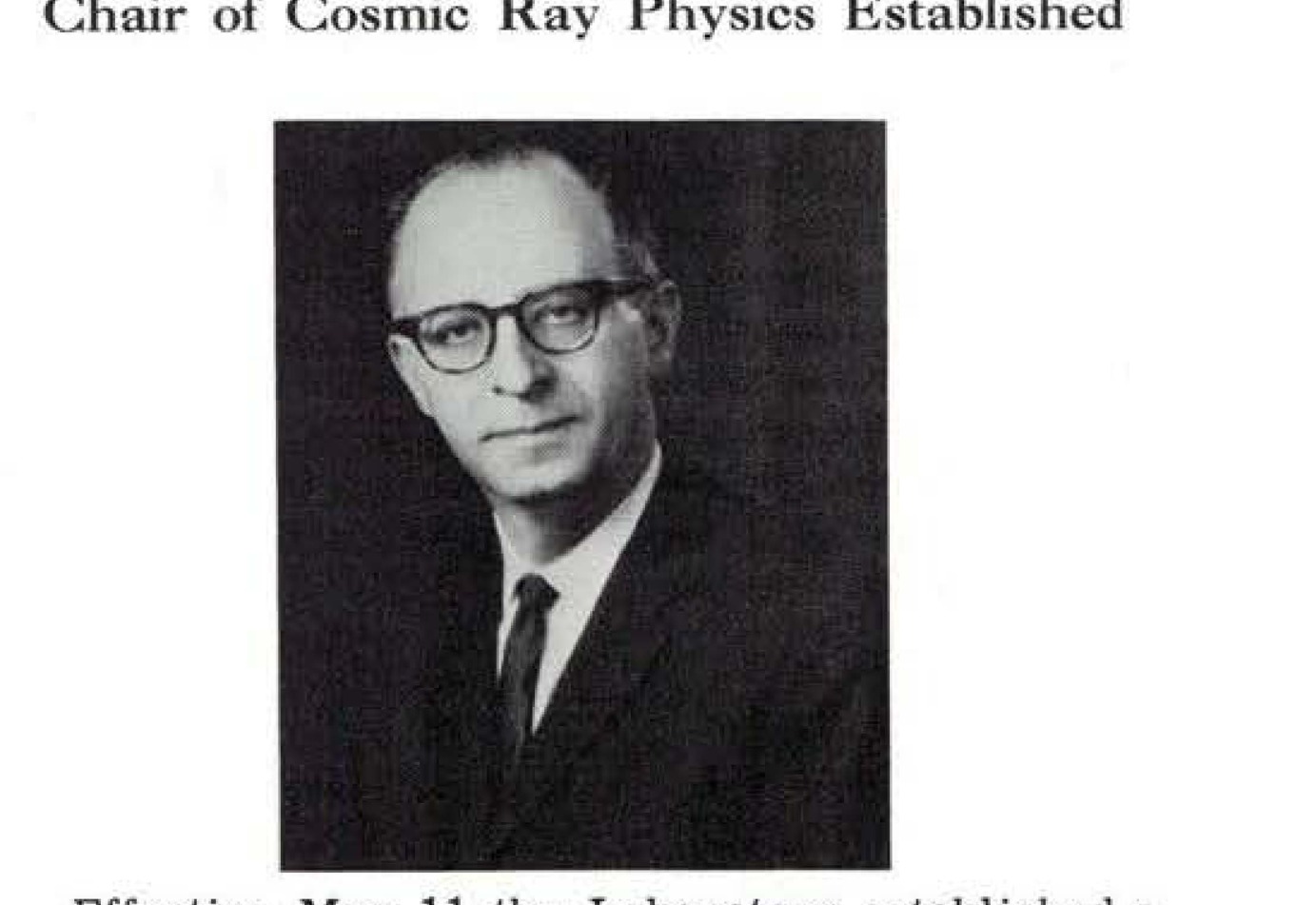
Photograph of Dr. Maurice M. Shapiro.
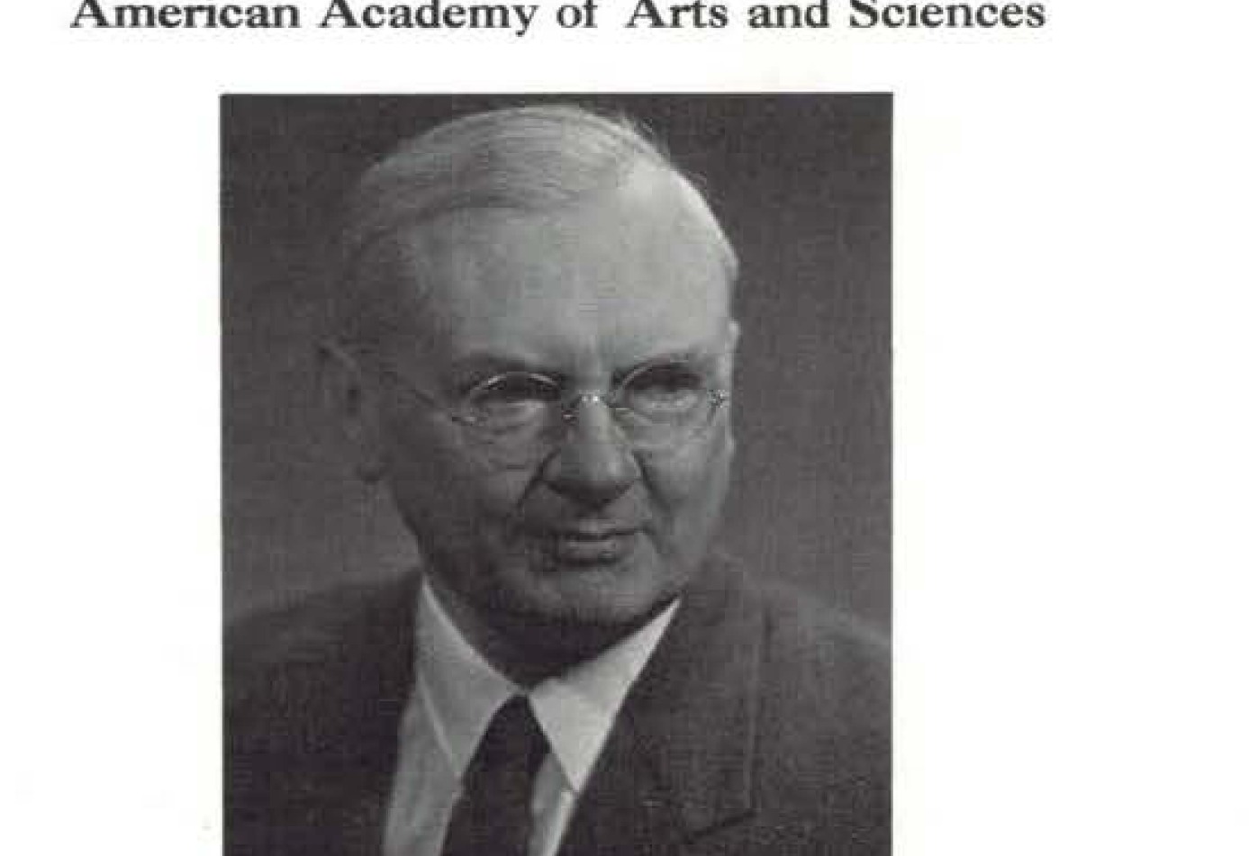
Photograph of Dr. Richard Tousey.
Sketch of a funnel-shaped flame.
Sketch of an oval-shaped object.
Sketch of an oval shape.
Sketch of an insignia.
Sketch of an insignia.
Sketch of a funnel-shaped flame.
Sketch of an oval-shaped object.
Sketch of an oval shape.
Sketch of an insignia.
Sketch of an insignia.
Sketch of a funnel-shaped flame.
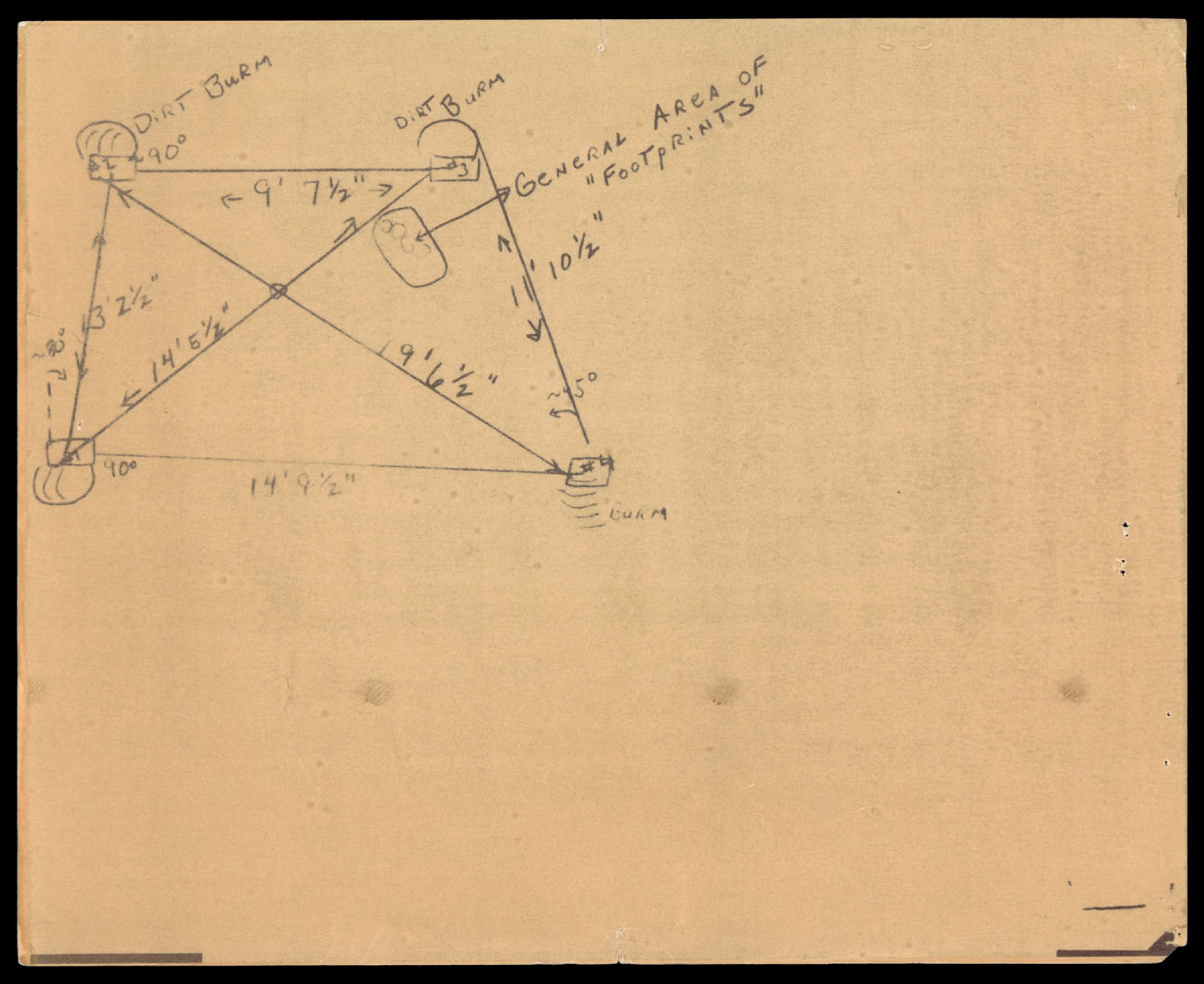
Hand-drawn diagram of landing site with measurements and labels for 'DIRT BURM' and 'FOOTPRINTS'.
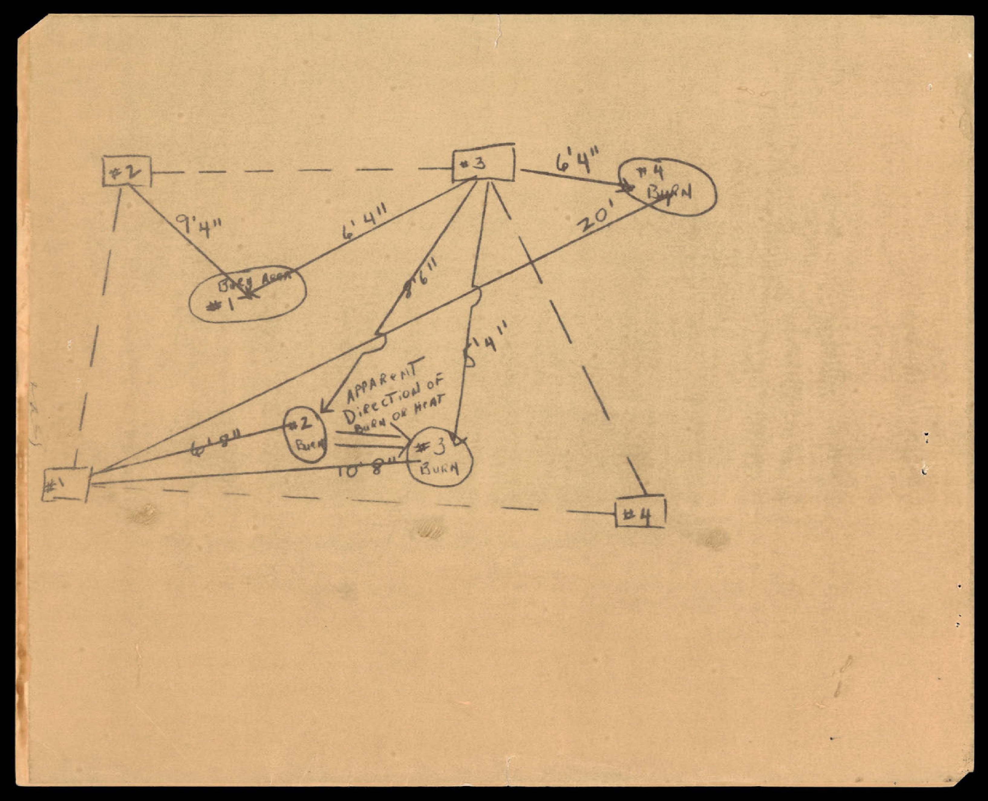
Hand-drawn diagram showing burn marks and their relative positions and distances.

Seal of the Department of State.
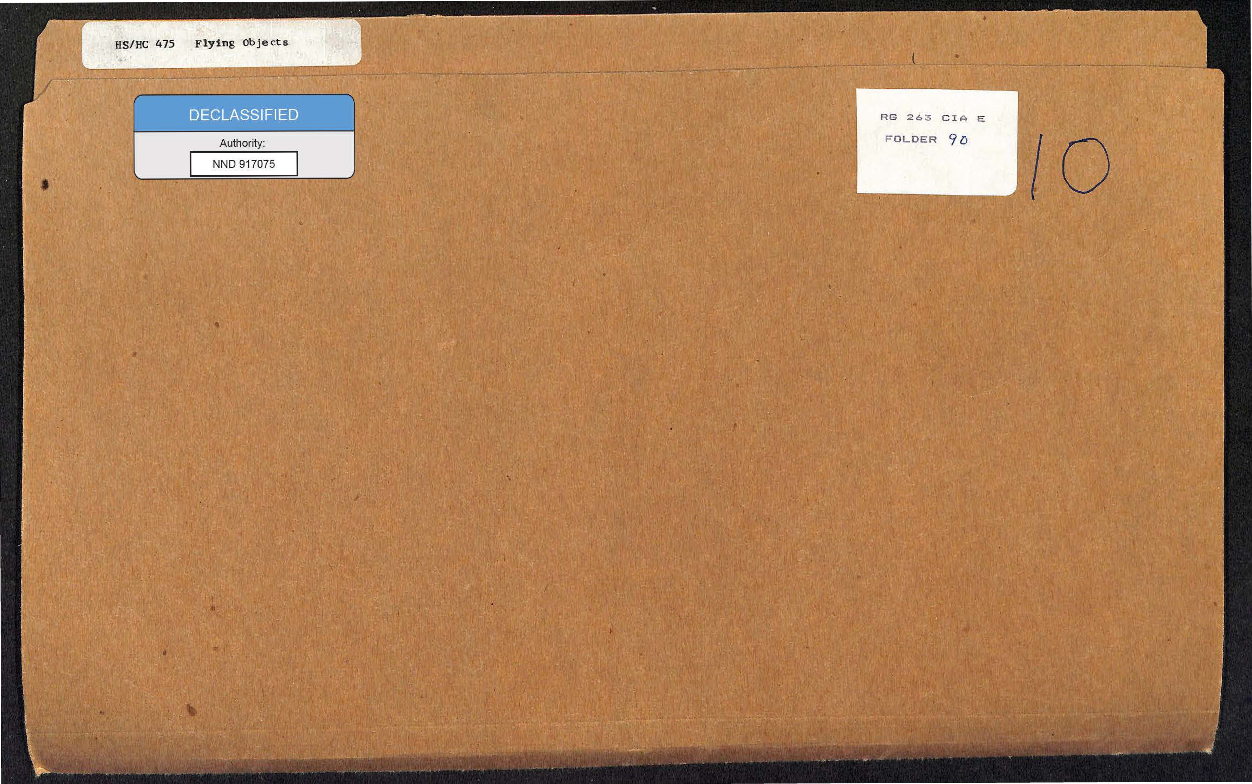
A photograph of a cardboard file folder with several labels.
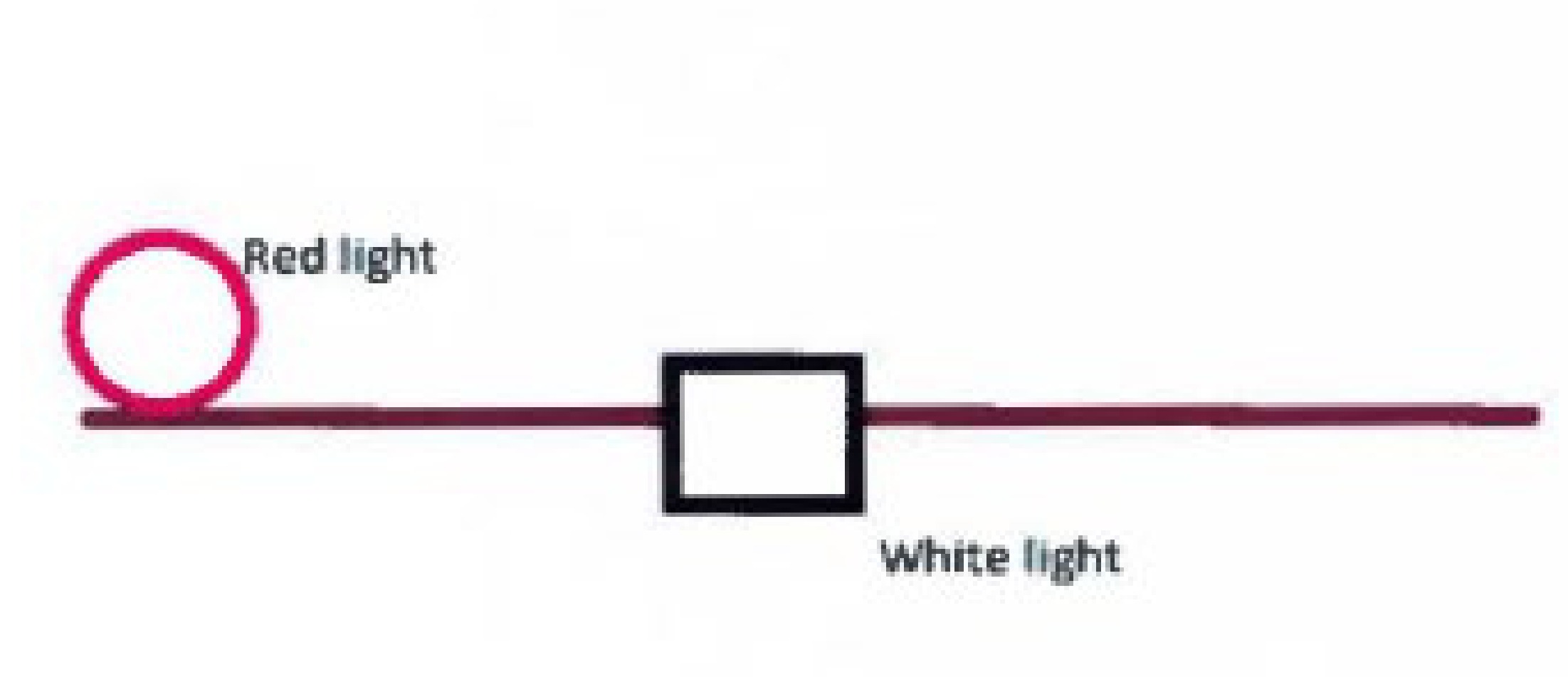
Image 1: Diagram showing a red circular light and a white square light connected by lines.
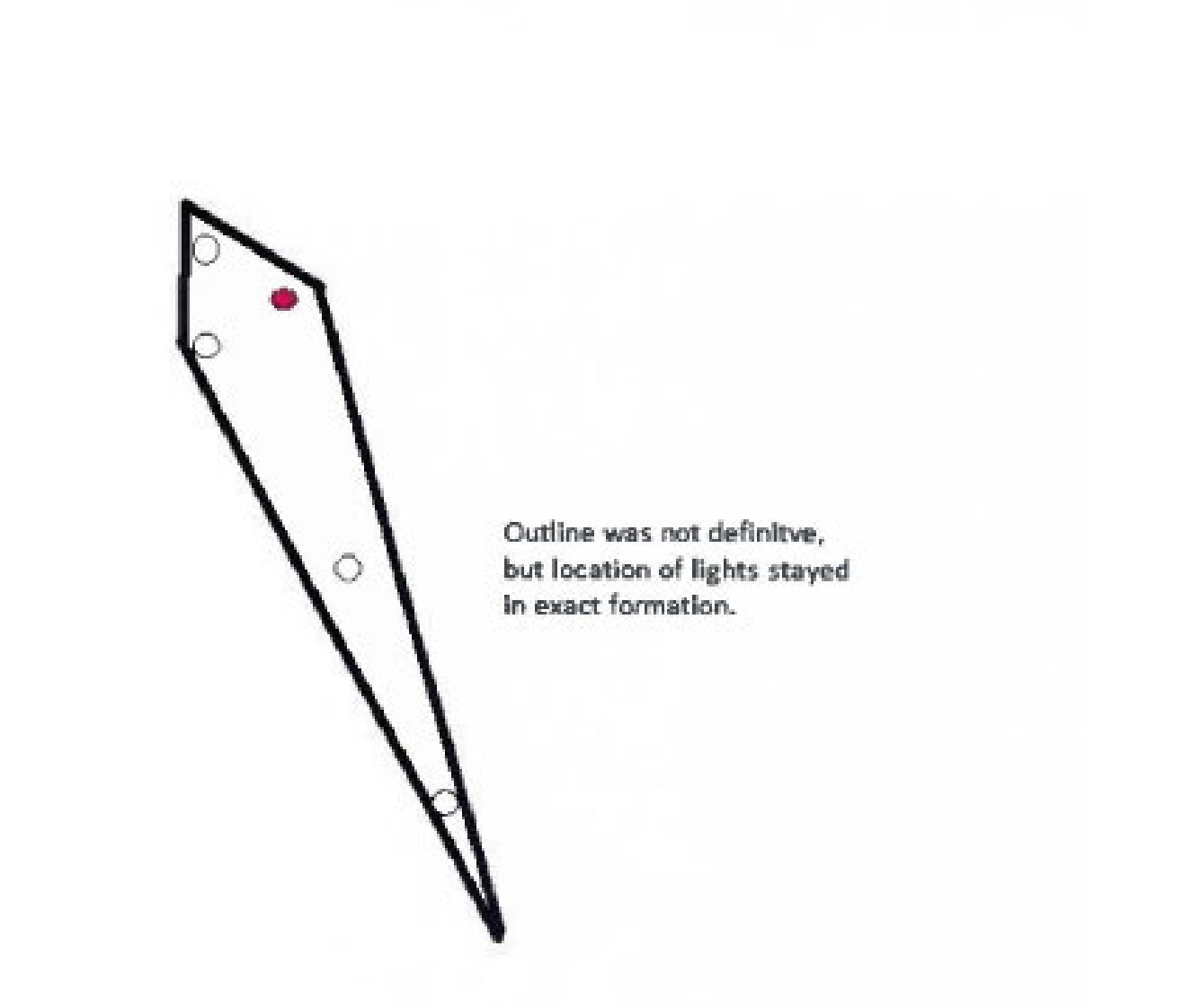
Image 2: Diagram showing a formation of faint lights in a pointed shape.
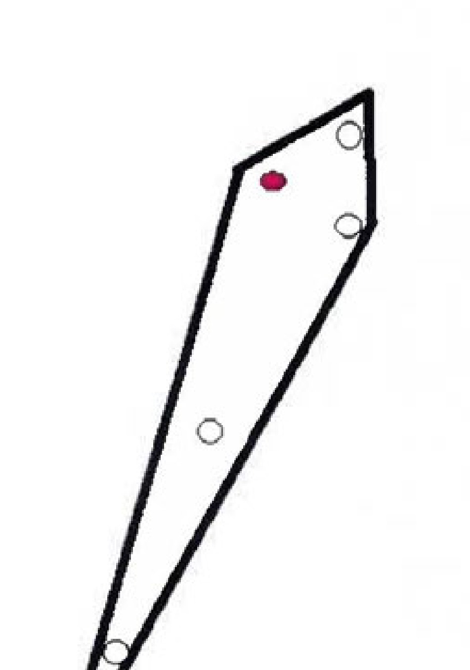
Image 3: Diagram showing a formation of faint lights in a pointed shape, at a different angle from Image 2.
Flying saucer photograph over forested landscape with clouds
Photograph of a flying saucer over a desert landscape.
Photograph of a flying saucer over a forested landscape.
Photograph of a flying saucer.
Photograph of a flying saucer.
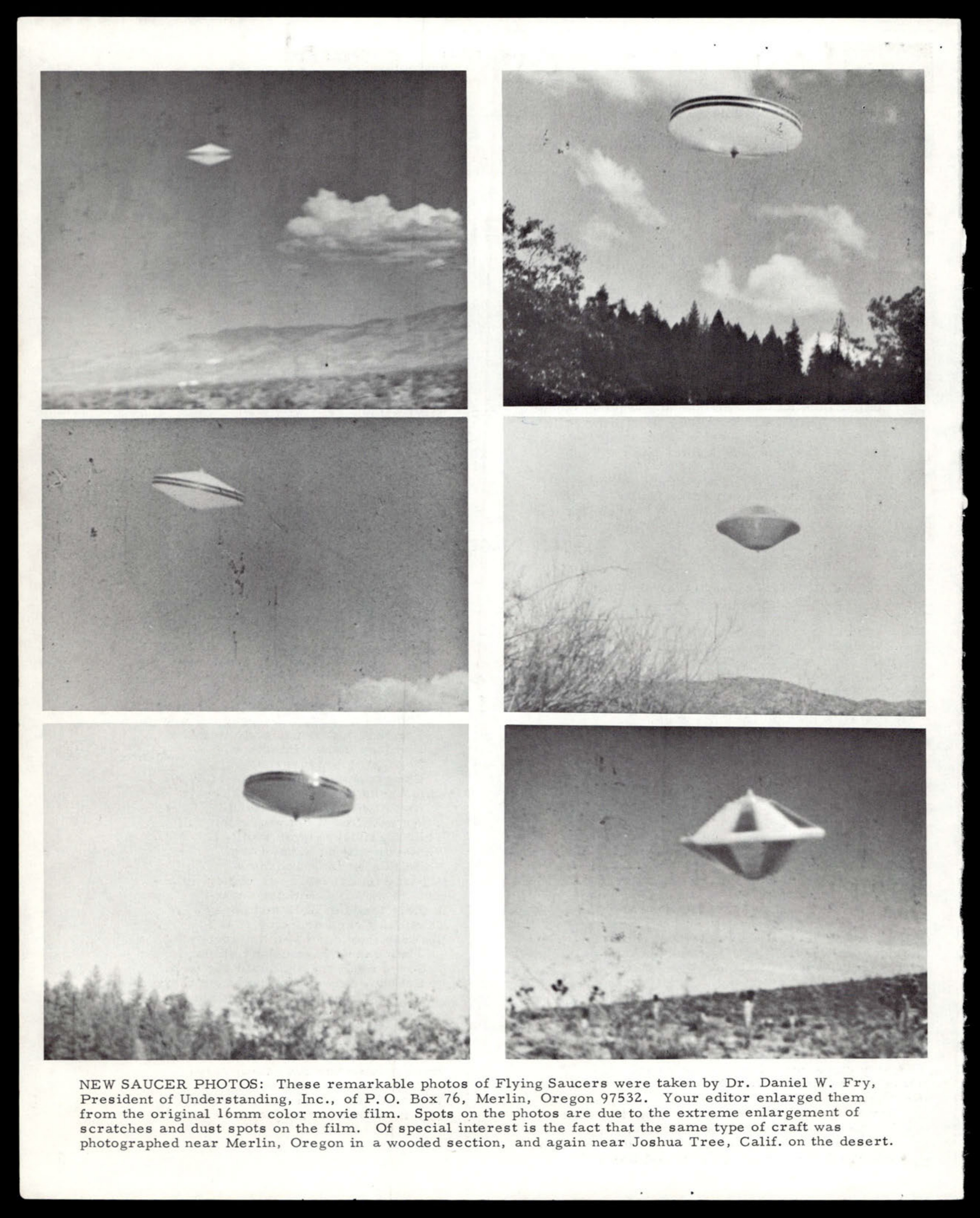
A composite of six photographs showing flying saucer-type objects in various outdoor settings.
Small square logo, possibly a unit insignia or form symbol.
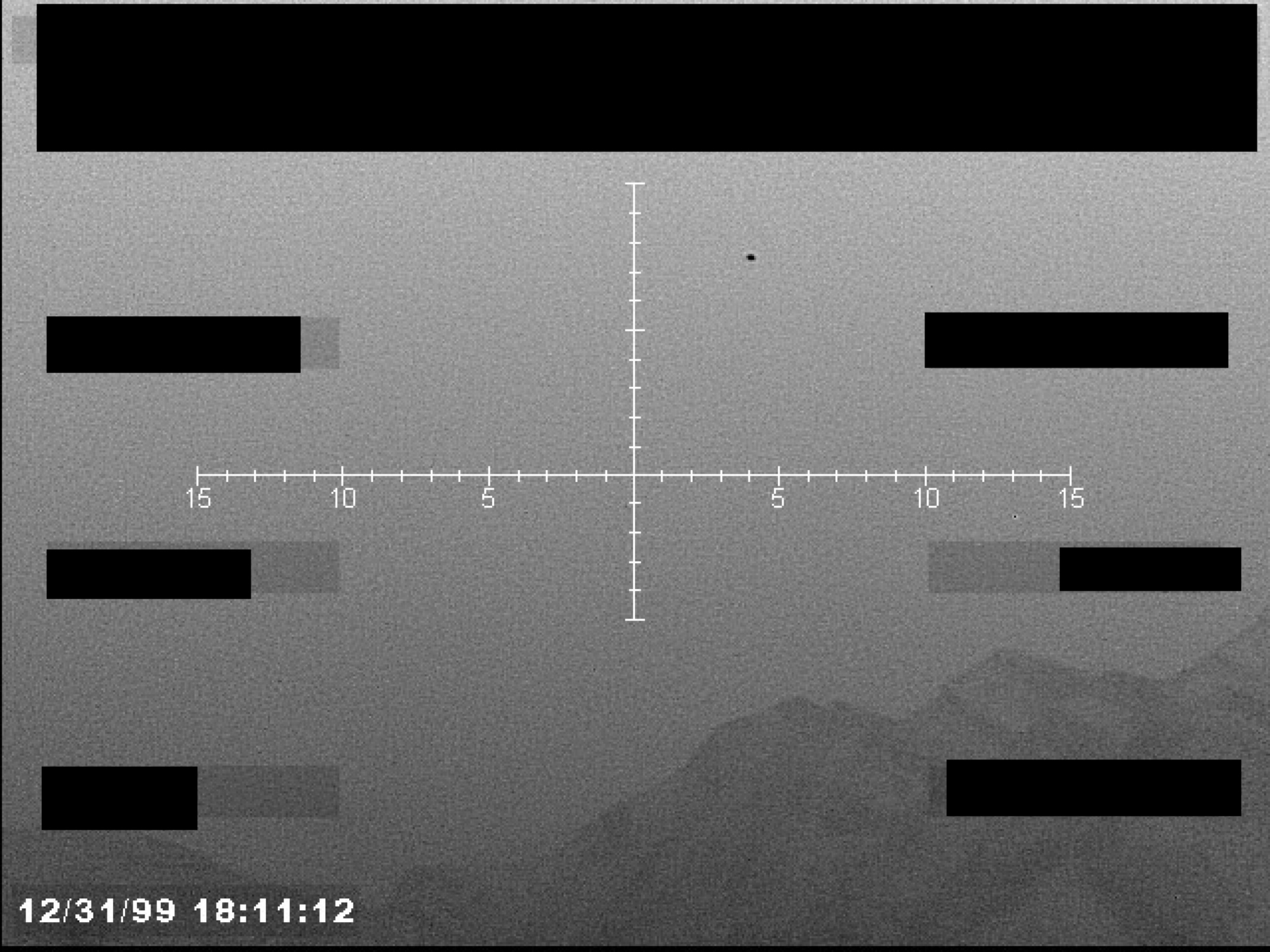
Sensor footage showing a reticle, a small dark object, and redacted data blocks over a grainy landscape.
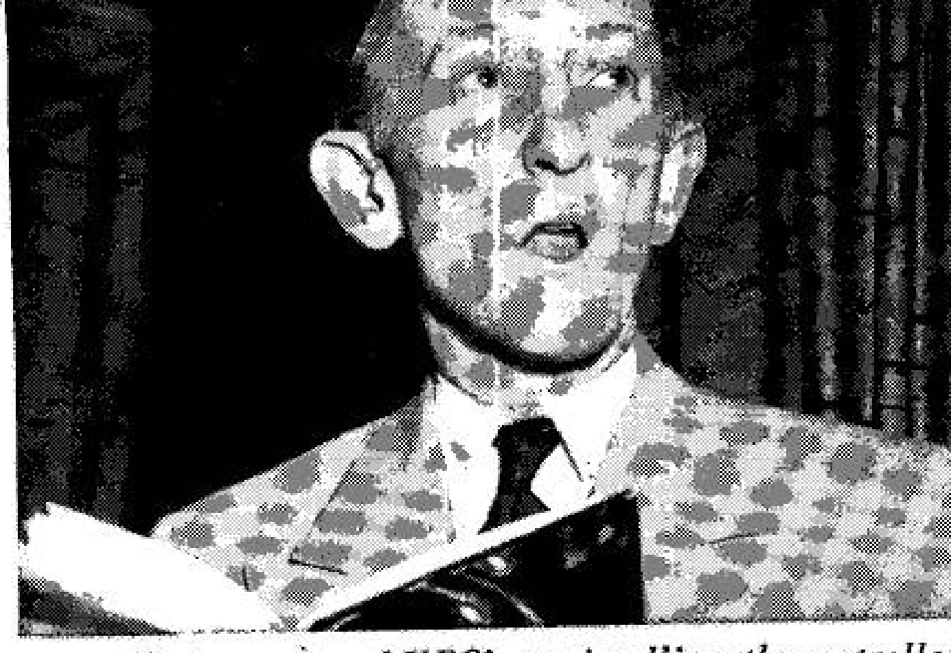
Photograph of Donald E. Keyoe.
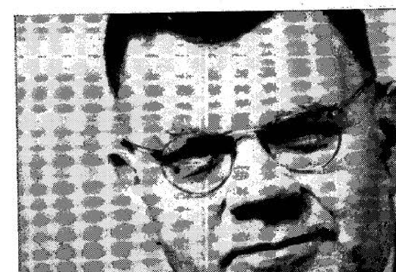
Photograph of Dr. Edward Condon.
Logo for the Inter-Continental Aerial Research Foundation, depicting a stylized flying object.
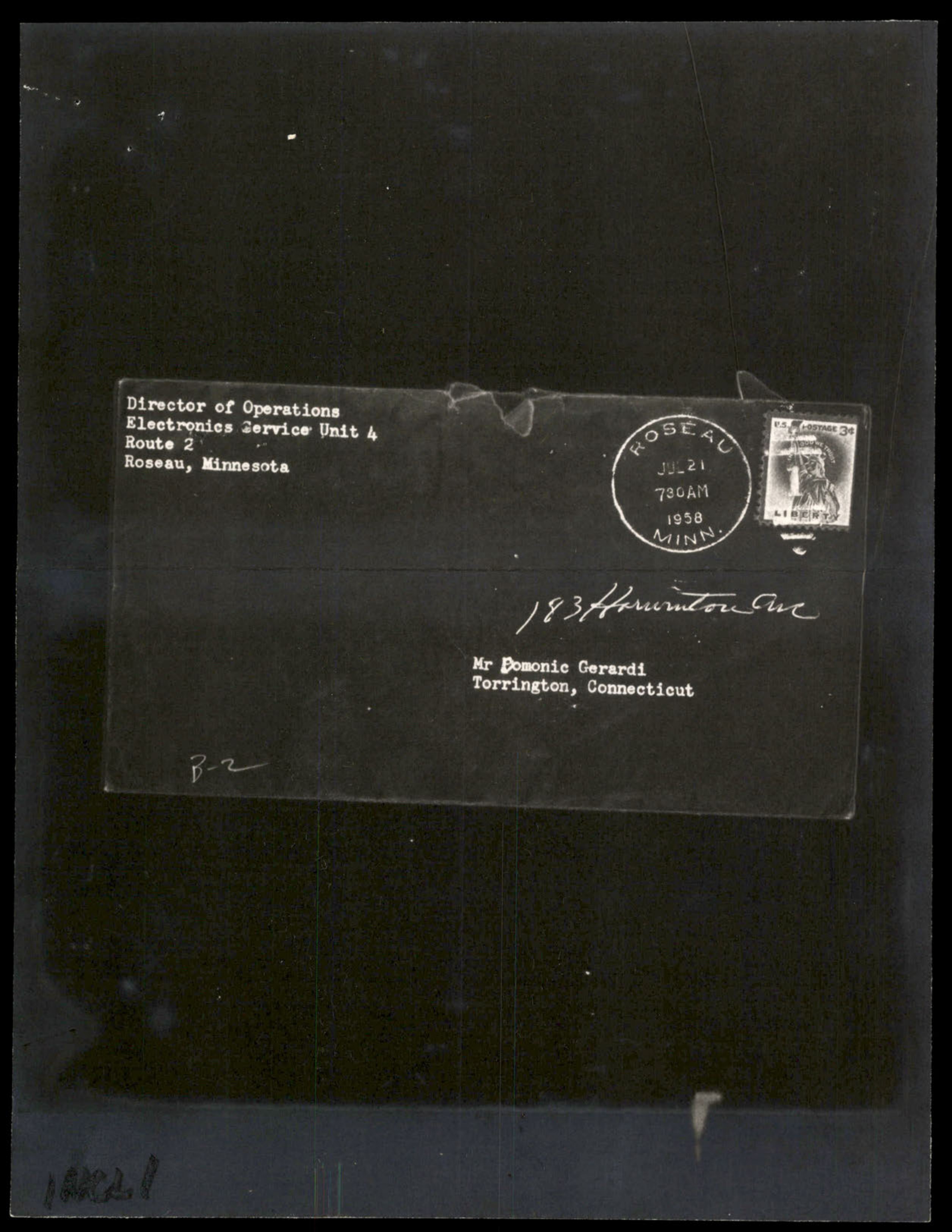
Photograph of an envelope addressed to Mr Domonic Gerardi in Torrington, Connecticut.
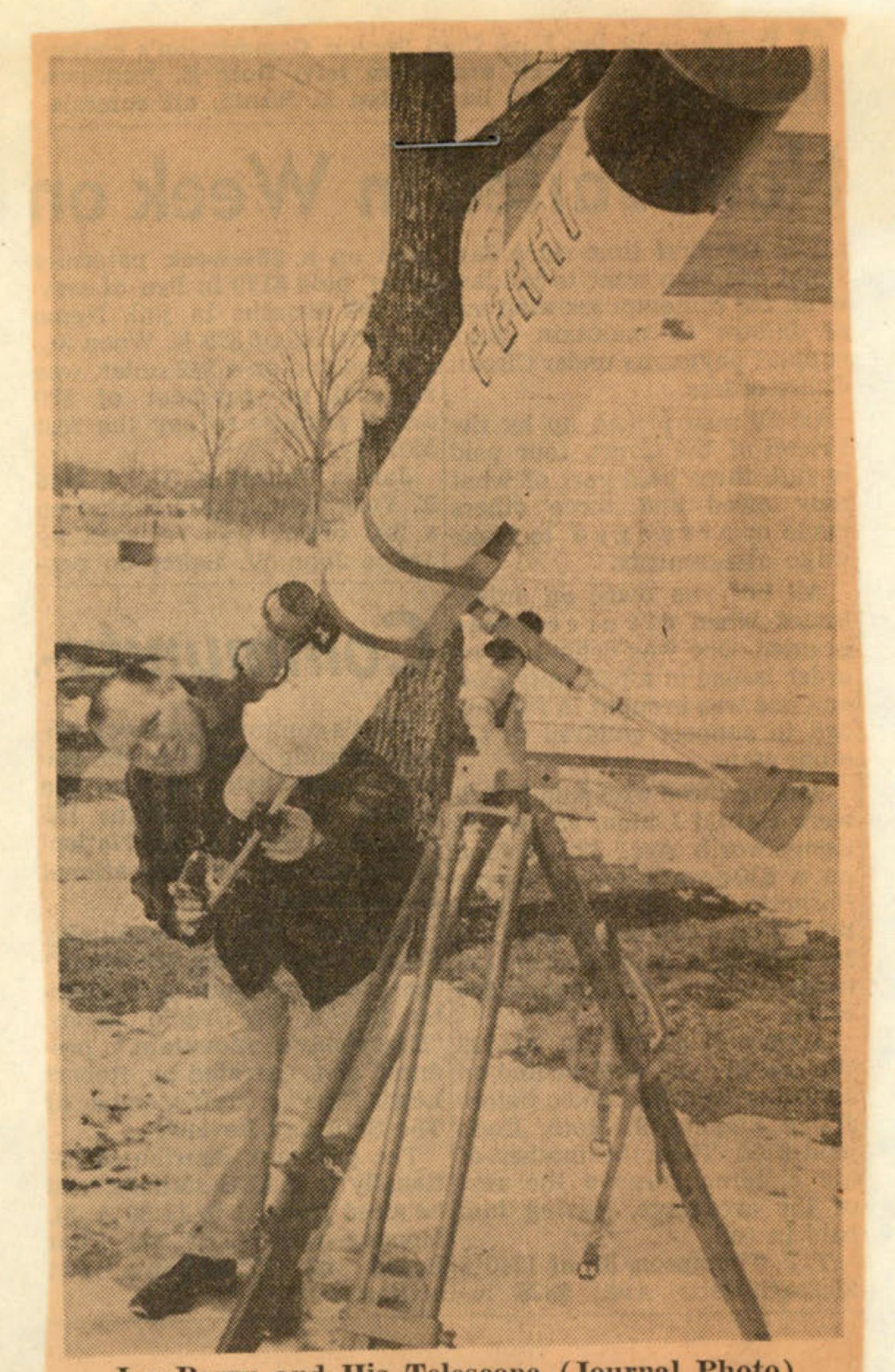
A black and white newspaper photograph showing a man, Joe Perry, standing next to a large, homemade telescope mounted on a tripod outdoors.
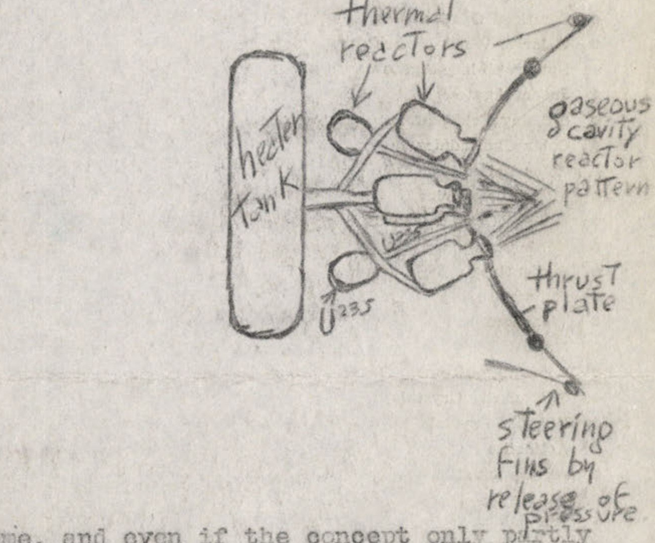
A hand-drawn diagram of a proposed propulsion system, labeled with terms like 'thermal reactors', 'gaseous cavity reactor pattern', and 'thrust plate'.
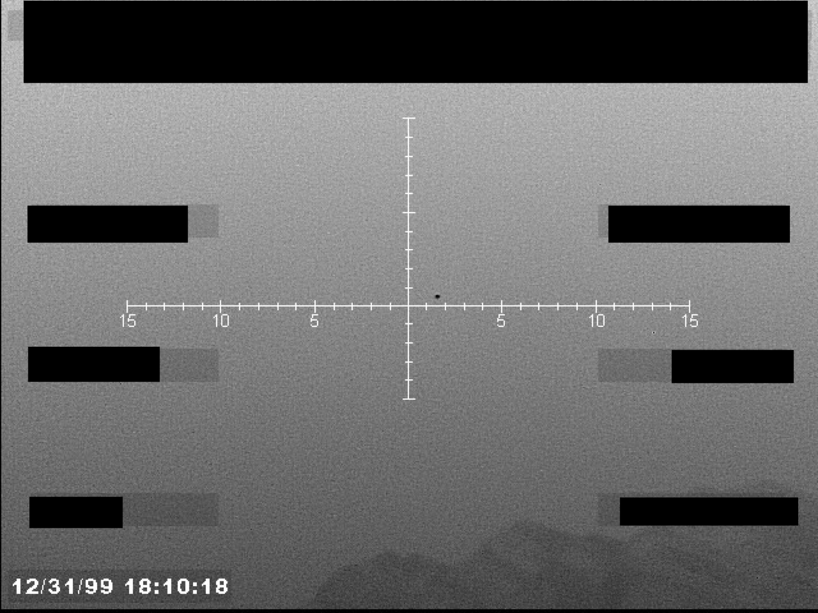
Sensor display, possibly infrared, showing a central crosshair targeting a small, dark, circular object against a grainy background. The display includes horizontal range markings and a timestamp in the lower-left corner.
Illustration of a person sweeping.
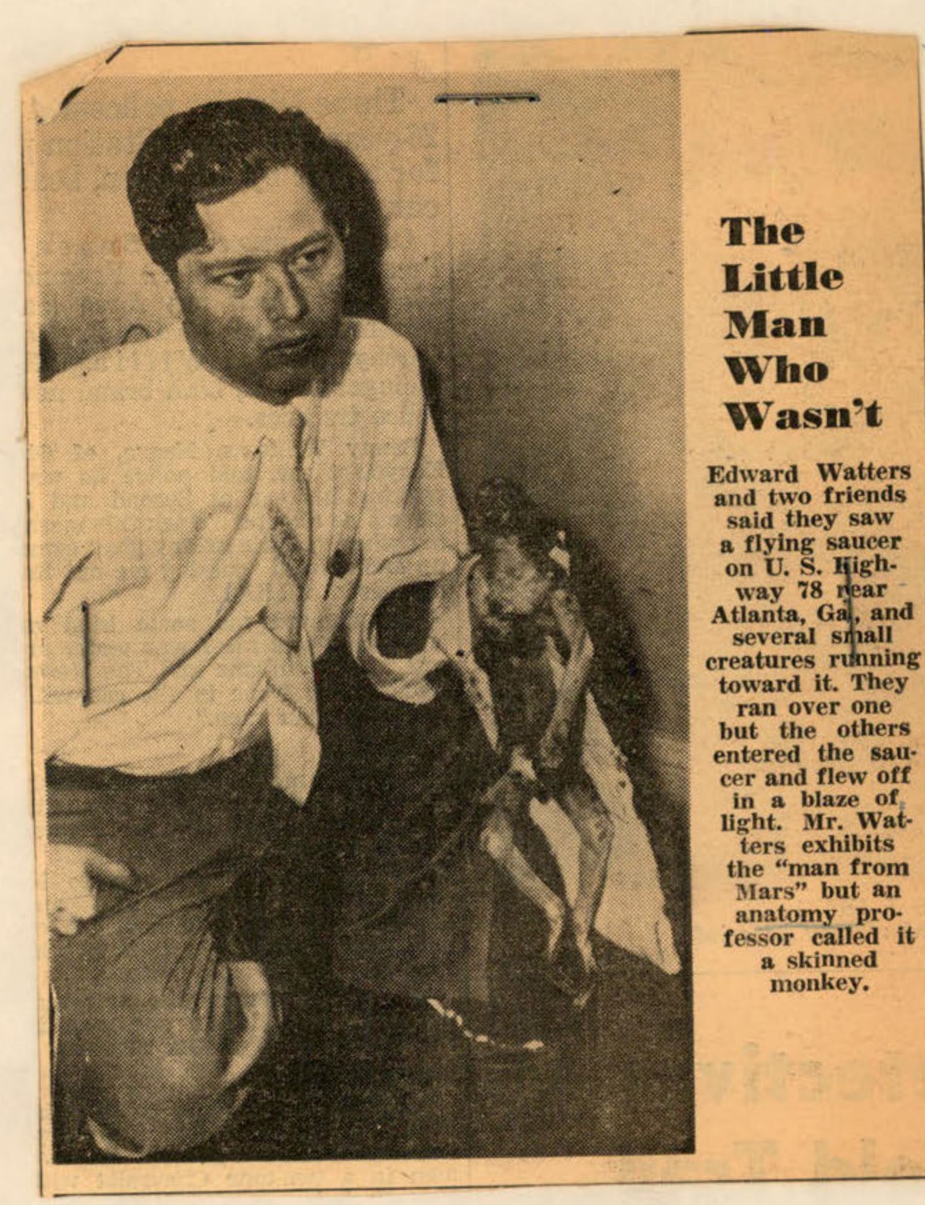
Newspaper clipping with a photo of Edward Watters holding a small, hairless creature, identified as a skinned monkey.
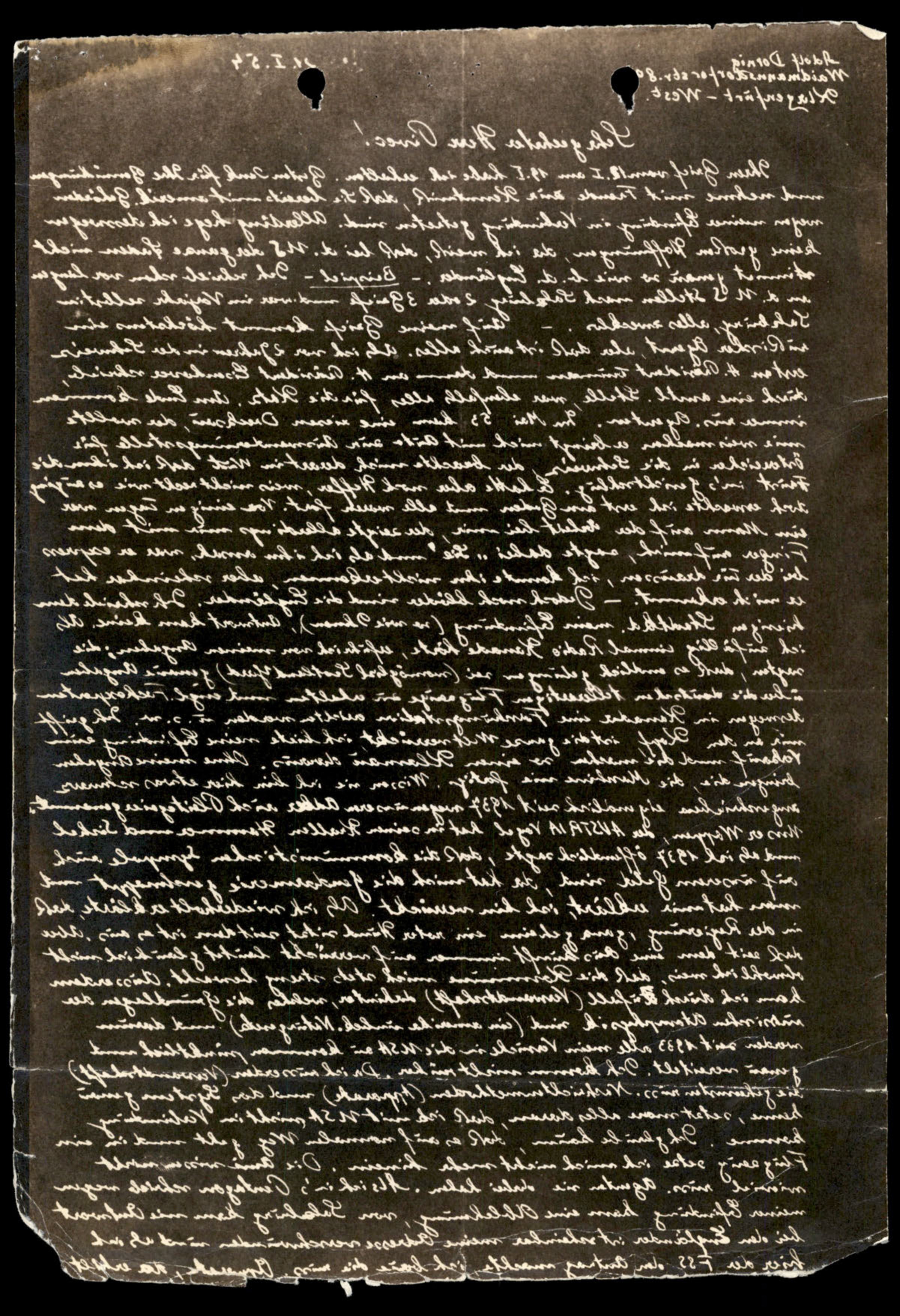
Photonegative of the handwritten letter on the previous page.
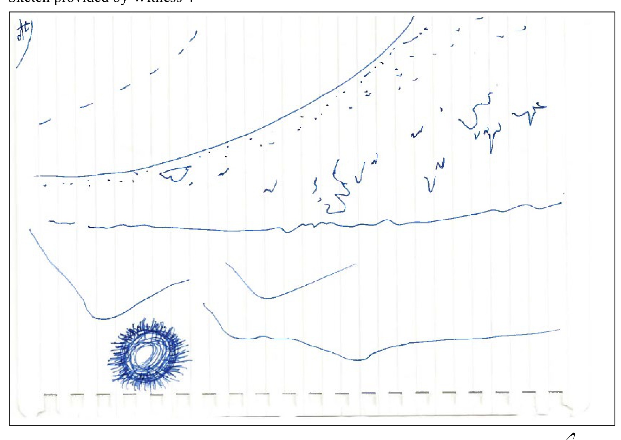
Sketch provided by Witness 4
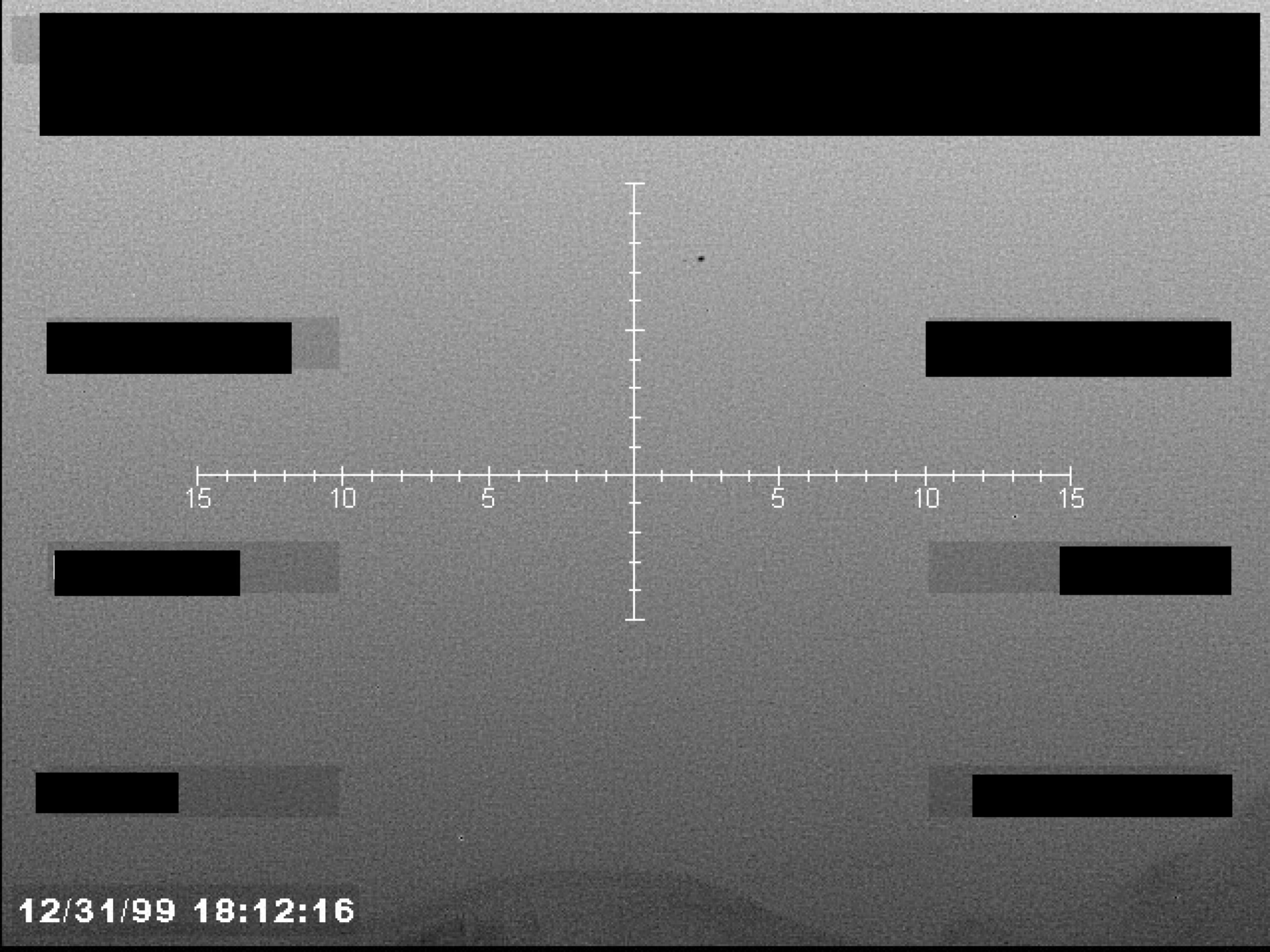
Page is a single frame from a sensor video, possibly Forward-Looking Infrared (FLIR), showing a targeting crosshair and timestamp. Several data fields are redacted with black boxes.
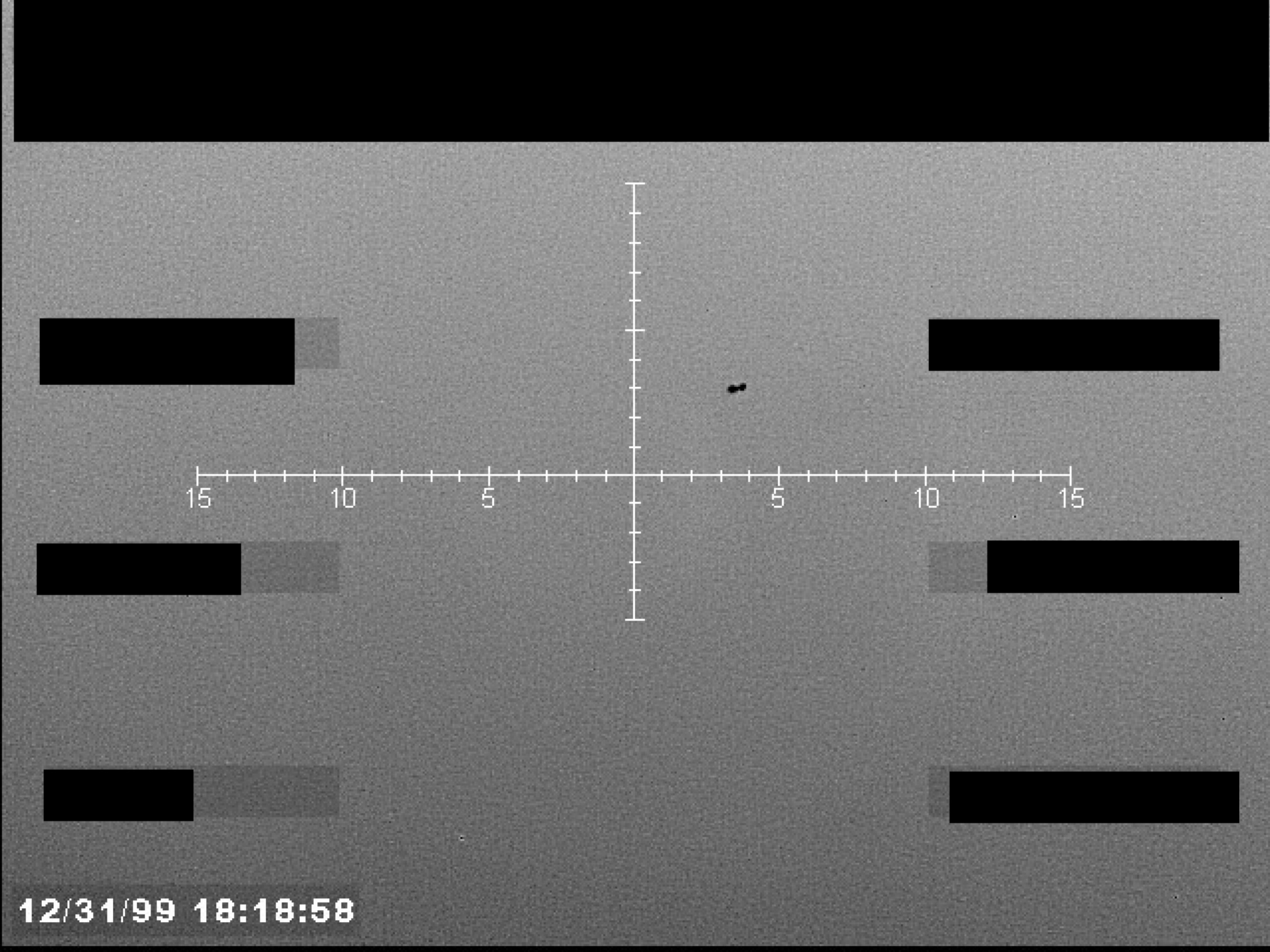
Sensor display showing a central crosshair reticle with numerical markings and an unidentified object near the center.
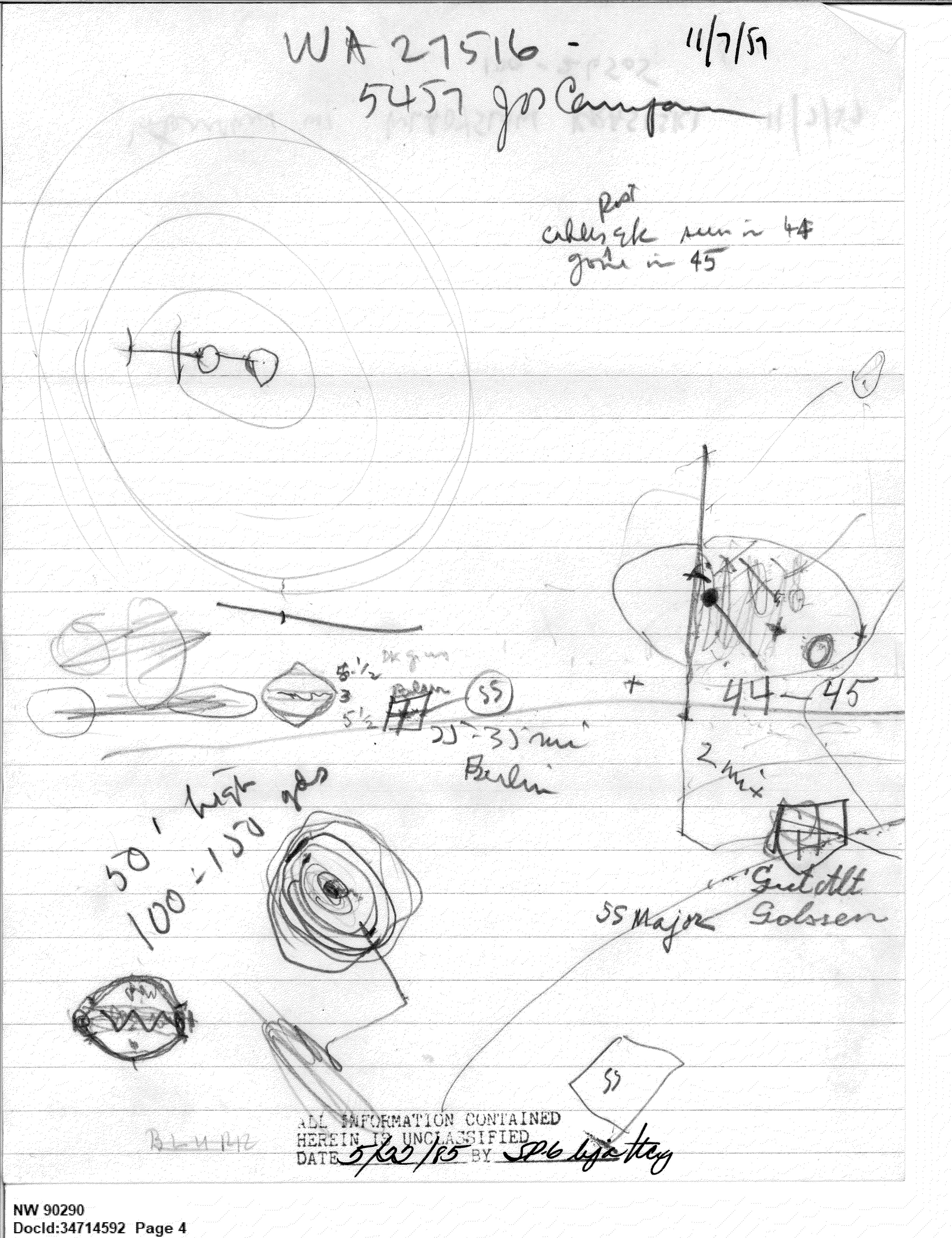
Handwritten sketches of circular objects, diagrams, and related notes.
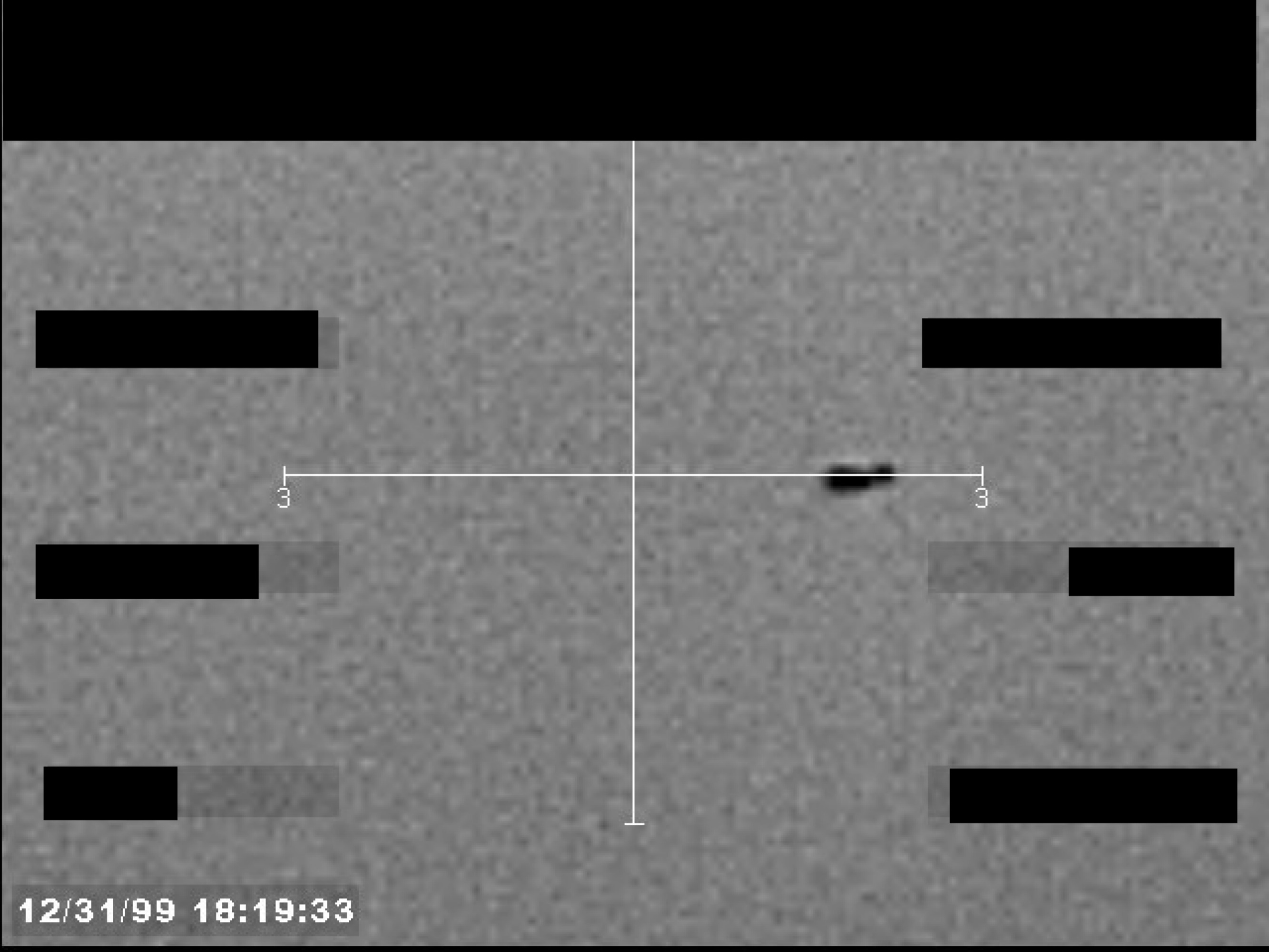
Sensor display showing a central crosshair and a small, dark, unidentified object. A timestamp '12/31/99 18:19:33' is visible in the bottom-left corner.
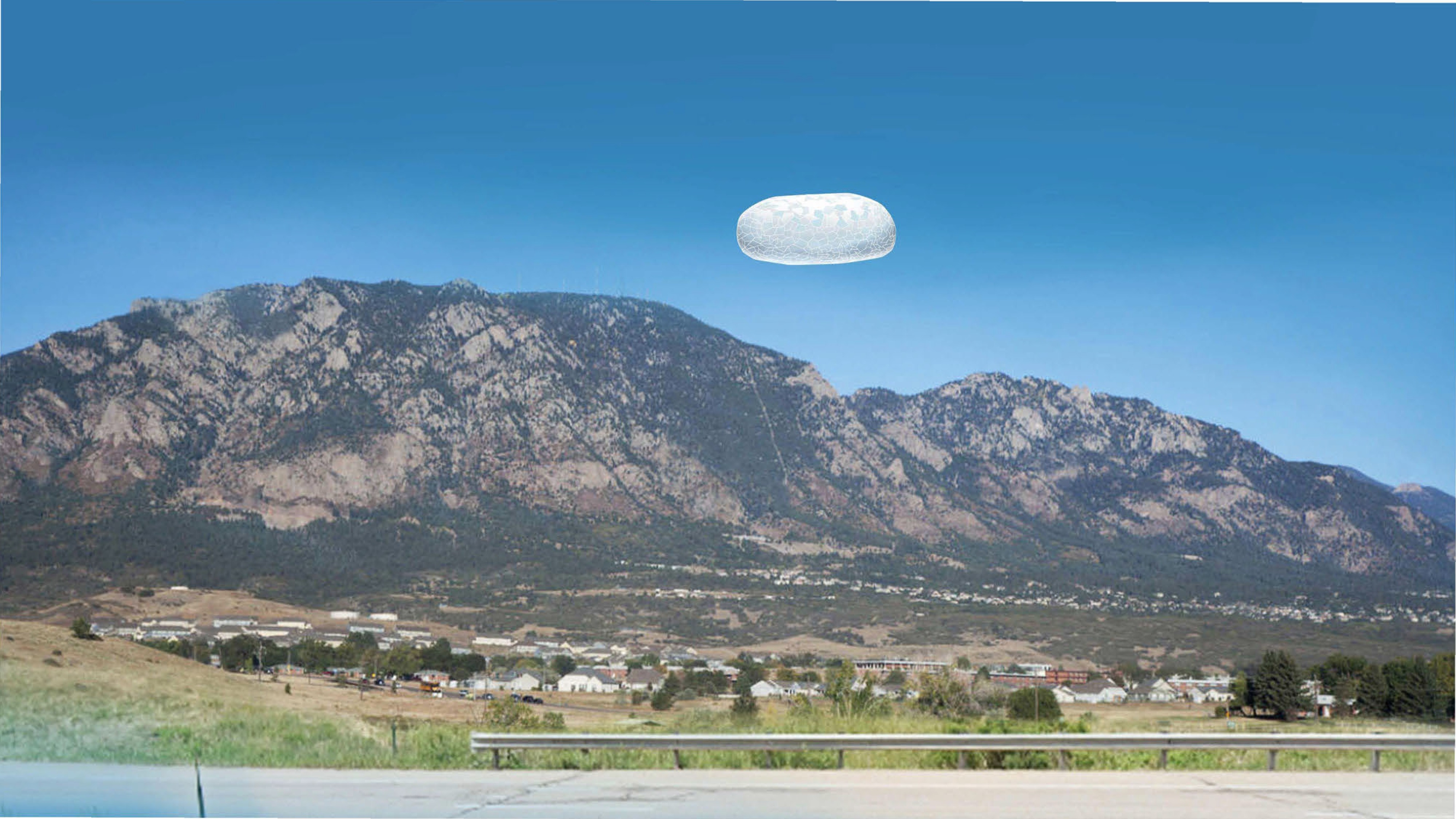
A photograph of a pill-shaped, translucent object hovering in the sky above a mountain range and a small town.
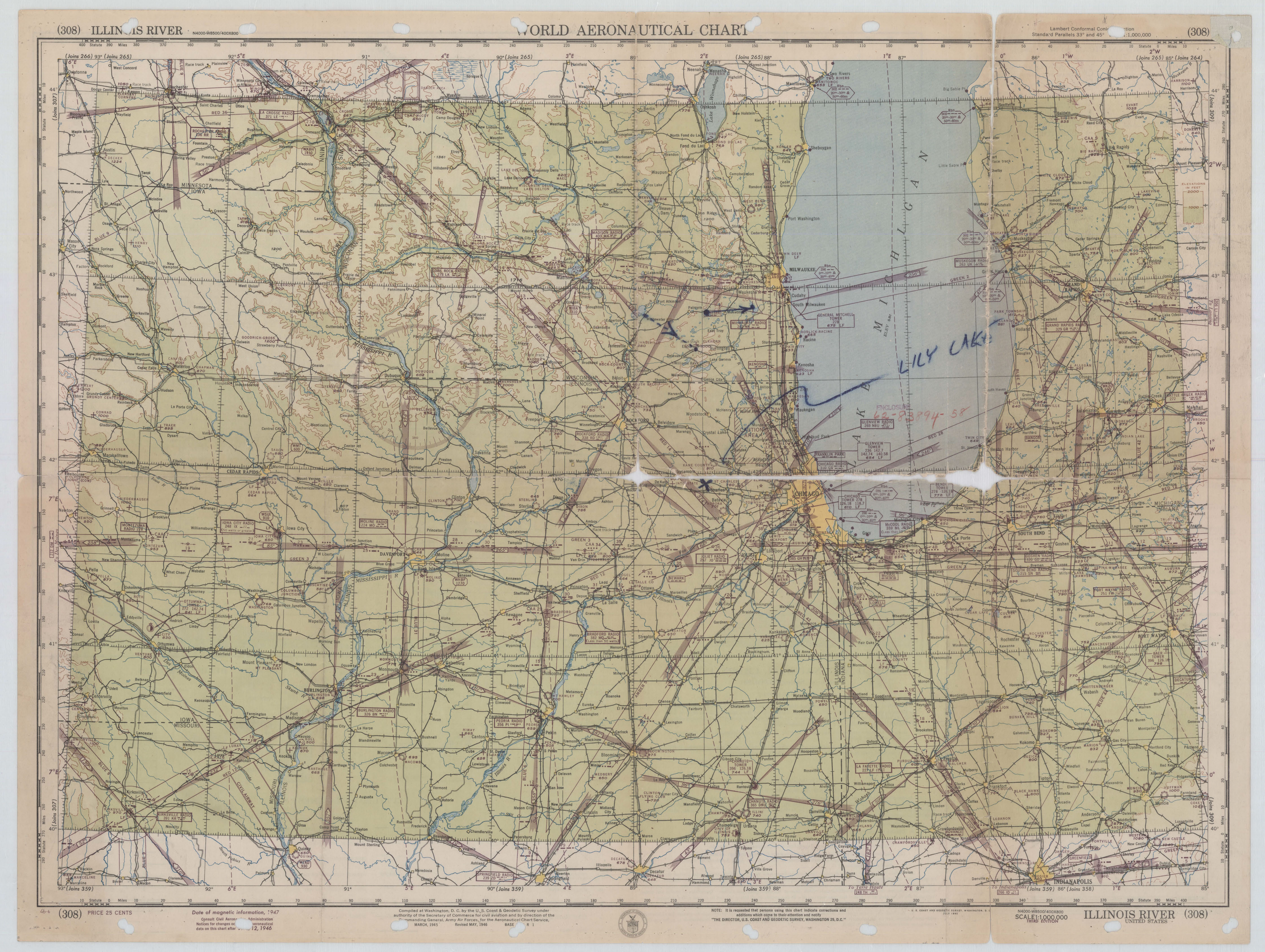
World Aeronautical Chart (308) showing Illinois, with 'LILY LAKE' handwritten and circled near Chicago.
Legend and index for World Aeronautical Chart, including symbols, drainage features, relief features, and cultural features.
Photograph of a manila envelope with a handwritten file number.
Verso of previous page, showing grid paper with a handwritten file number.
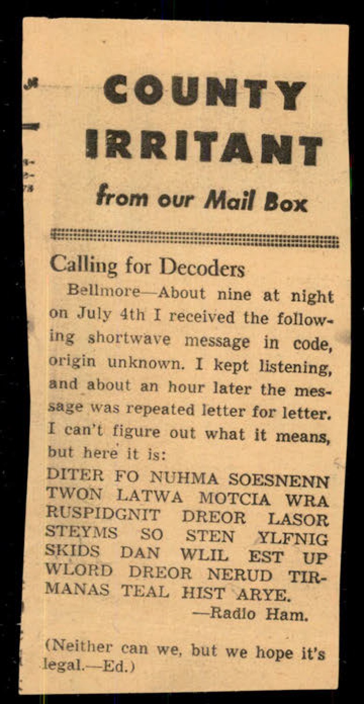
Newspaper clipping titled 'Calling for Decoders' from 'COUNTY IRRITANT from our Mail Box'.
Fragment of a newspaper clipping, likely the reverse of the clipping on the previous page.
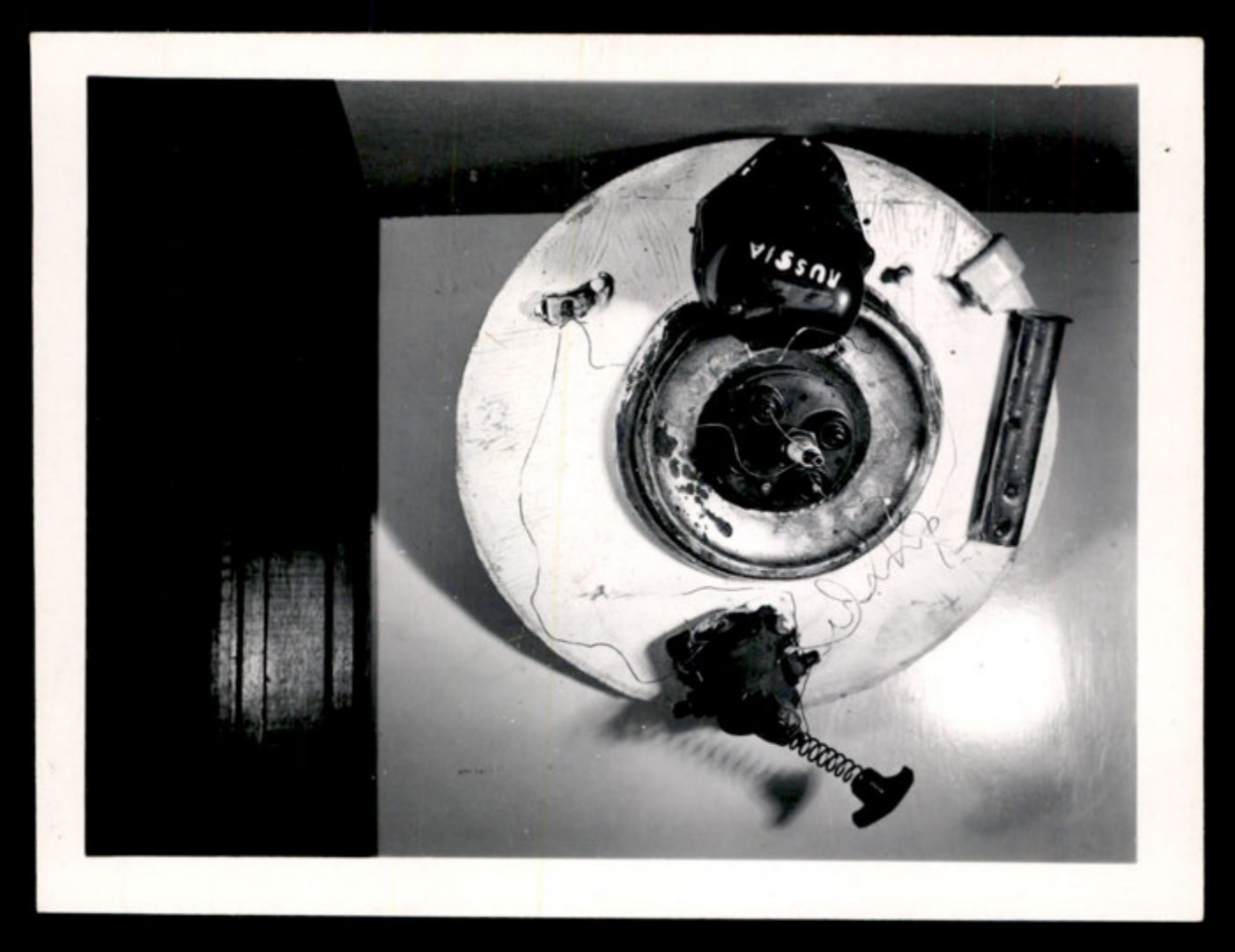
Overhead view of a constructed disc-shaped object with electronic components, one labeled 'RUSSIA'.
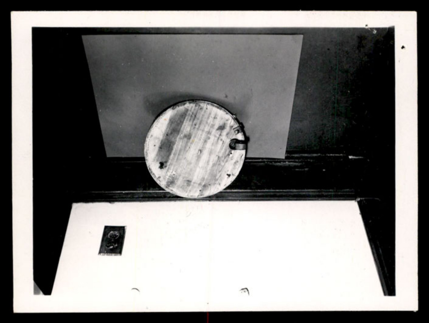
View of the bottom of the disc-shaped object.
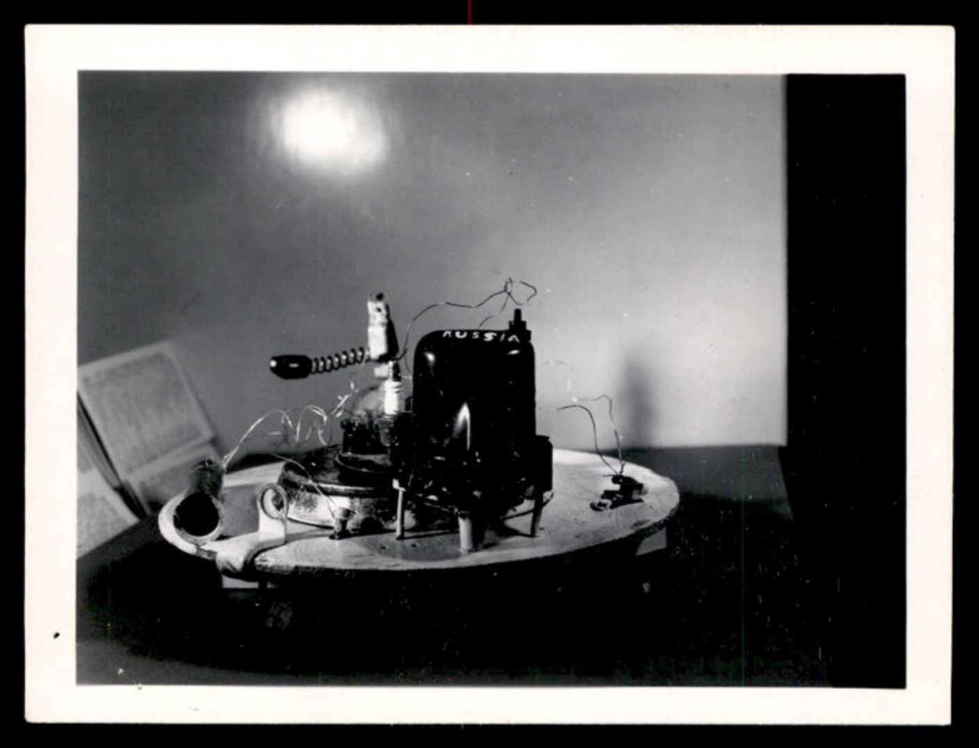
Side view of the constructed disc-shaped object, with a component labeled 'RUSSIA'.
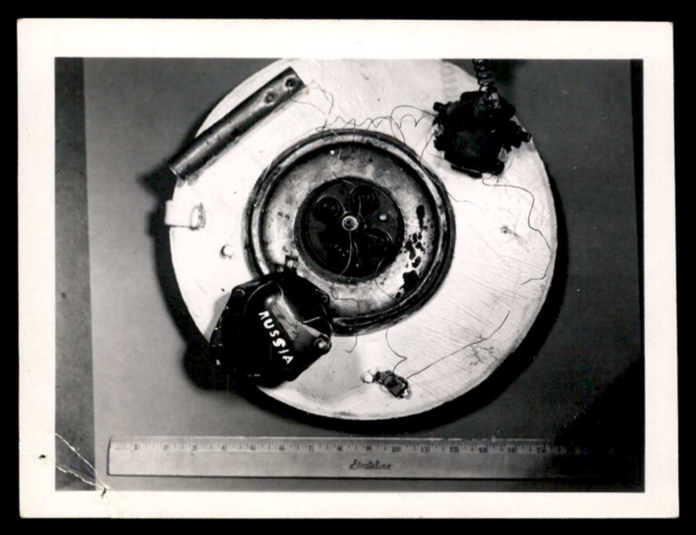
Overhead view of the disc-shaped object with a ruler for scale.
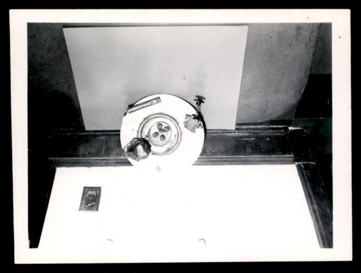
Angled view of the disc-shaped object.
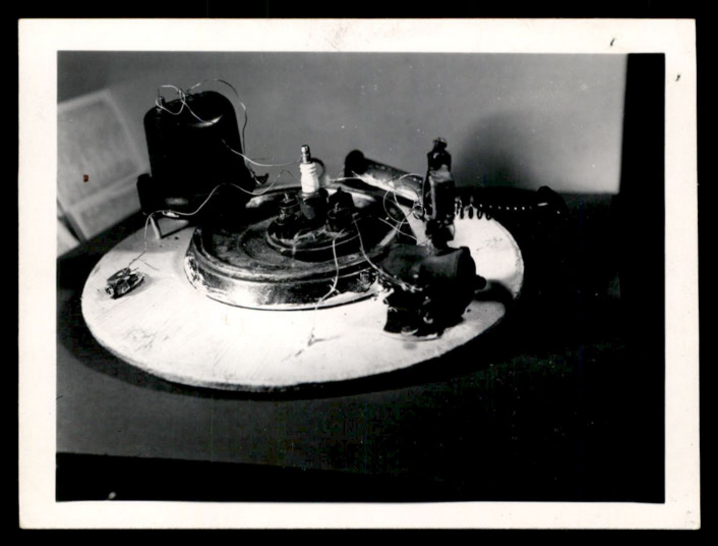
Side view of the disc-shaped object showing various components.
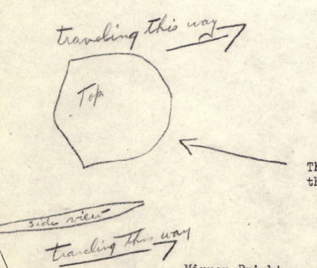
A handwritten sketch showing top and side views of a crescent-shaped object, with arrows indicating its direction of travel.
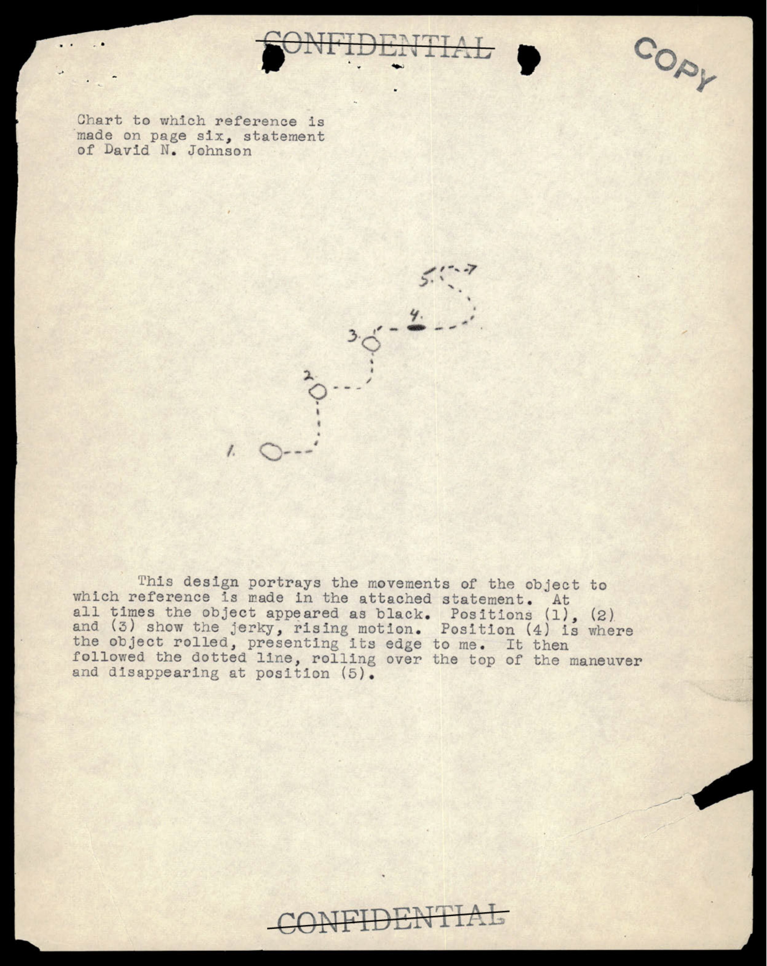
A numbered diagram showing the erratic, rising, and rolling flight path of an observed object.
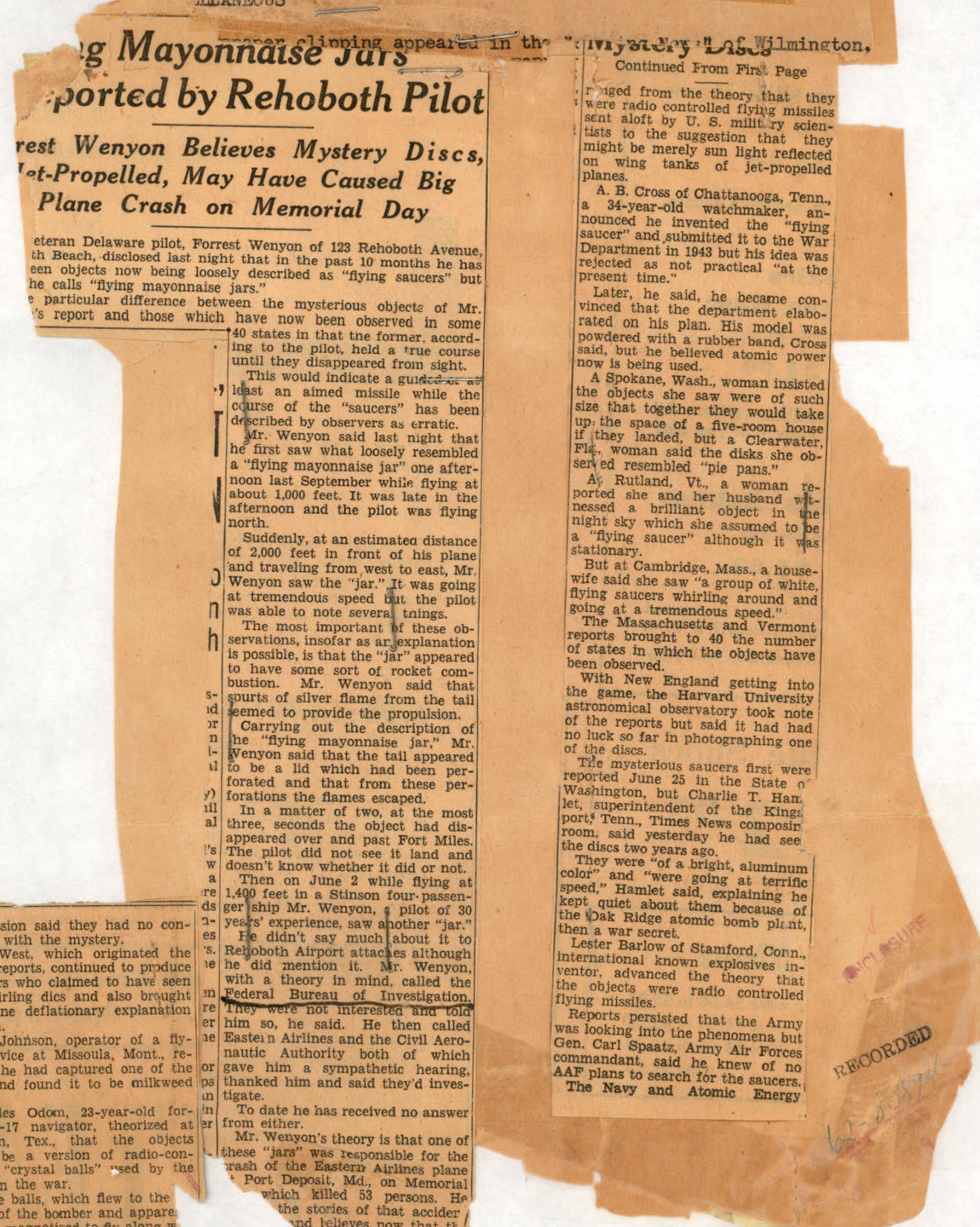
A newspaper clipping titled 'Flying Mayonnaise Jars Reported by Rehoboth Pilot' detailing sightings by Forrest Wenyon and others across the country.
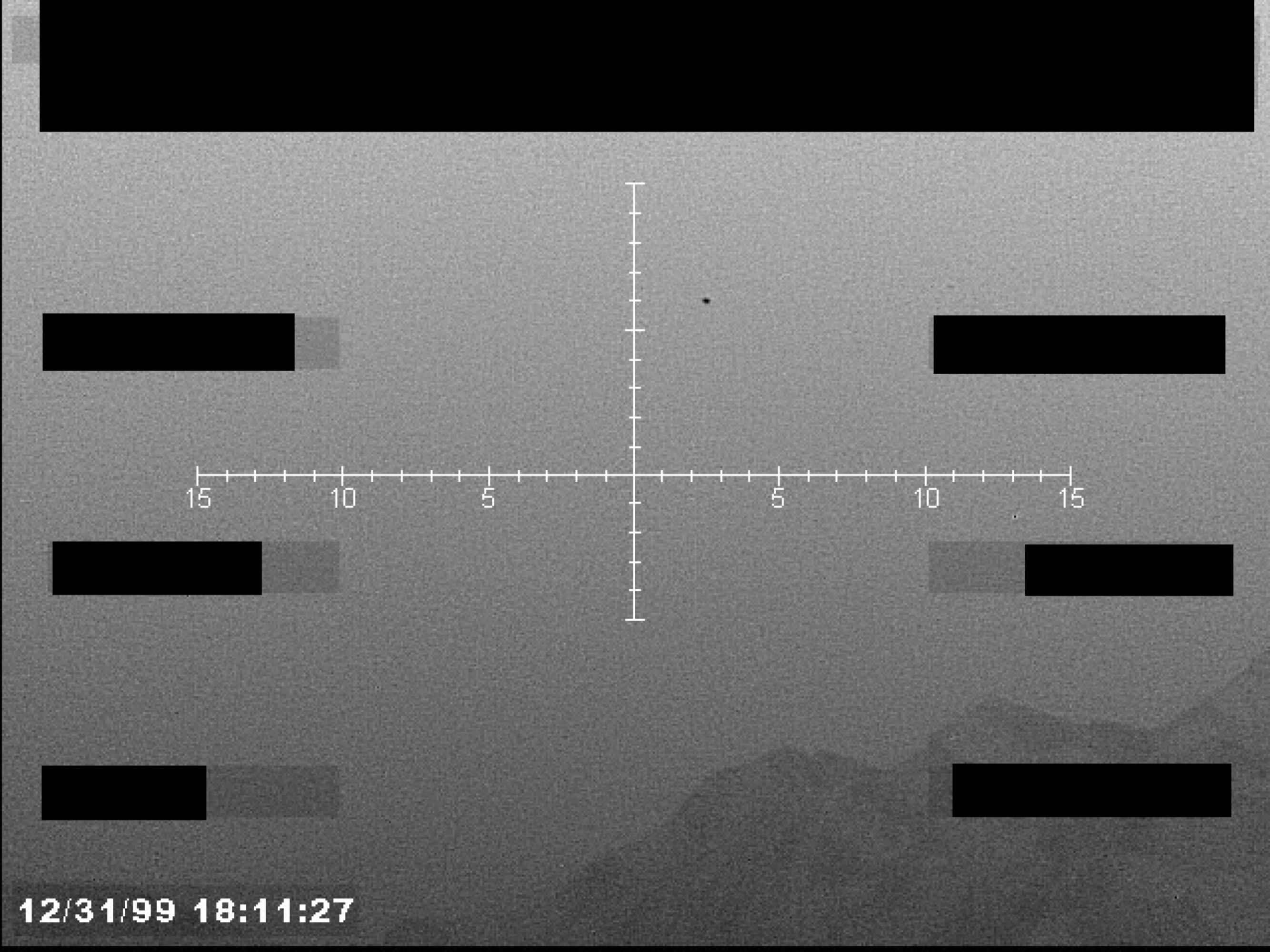
Sensor display with crosshairs, a small object near the center, and a timestamp. The background appears to be a mountainous or cloudy landscape.
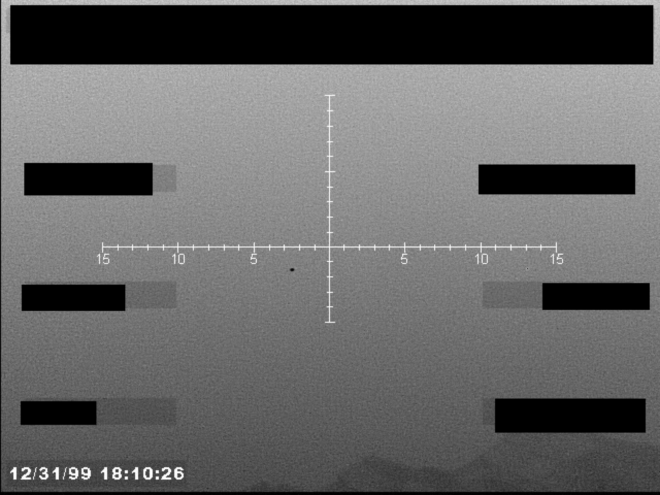
Sensor display with crosshairs, telemetry bars, and a timestamp, showing a small dark object near the center.
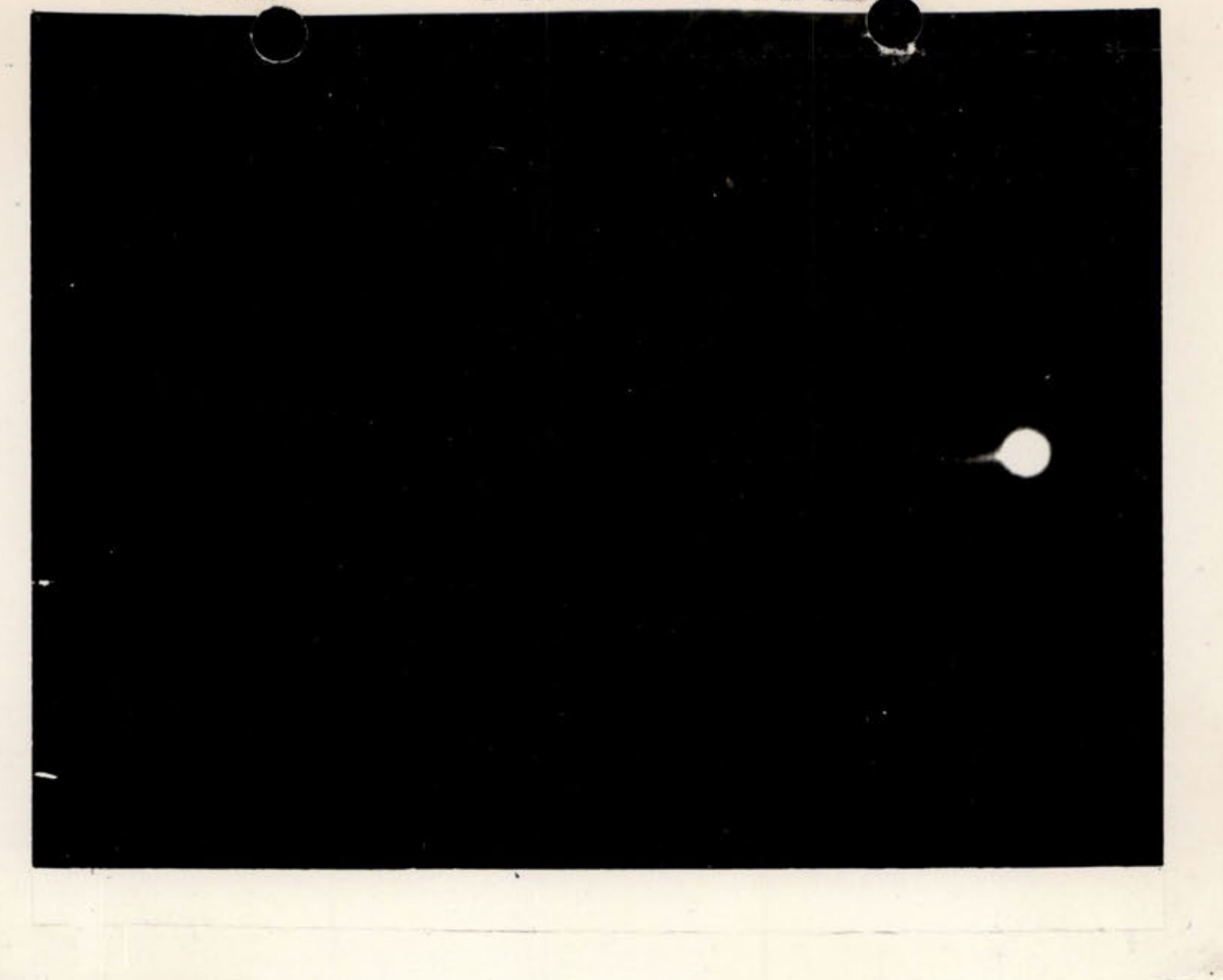
Photograph of Unknown Aerial Phenomena taken at Datil, New Mexico
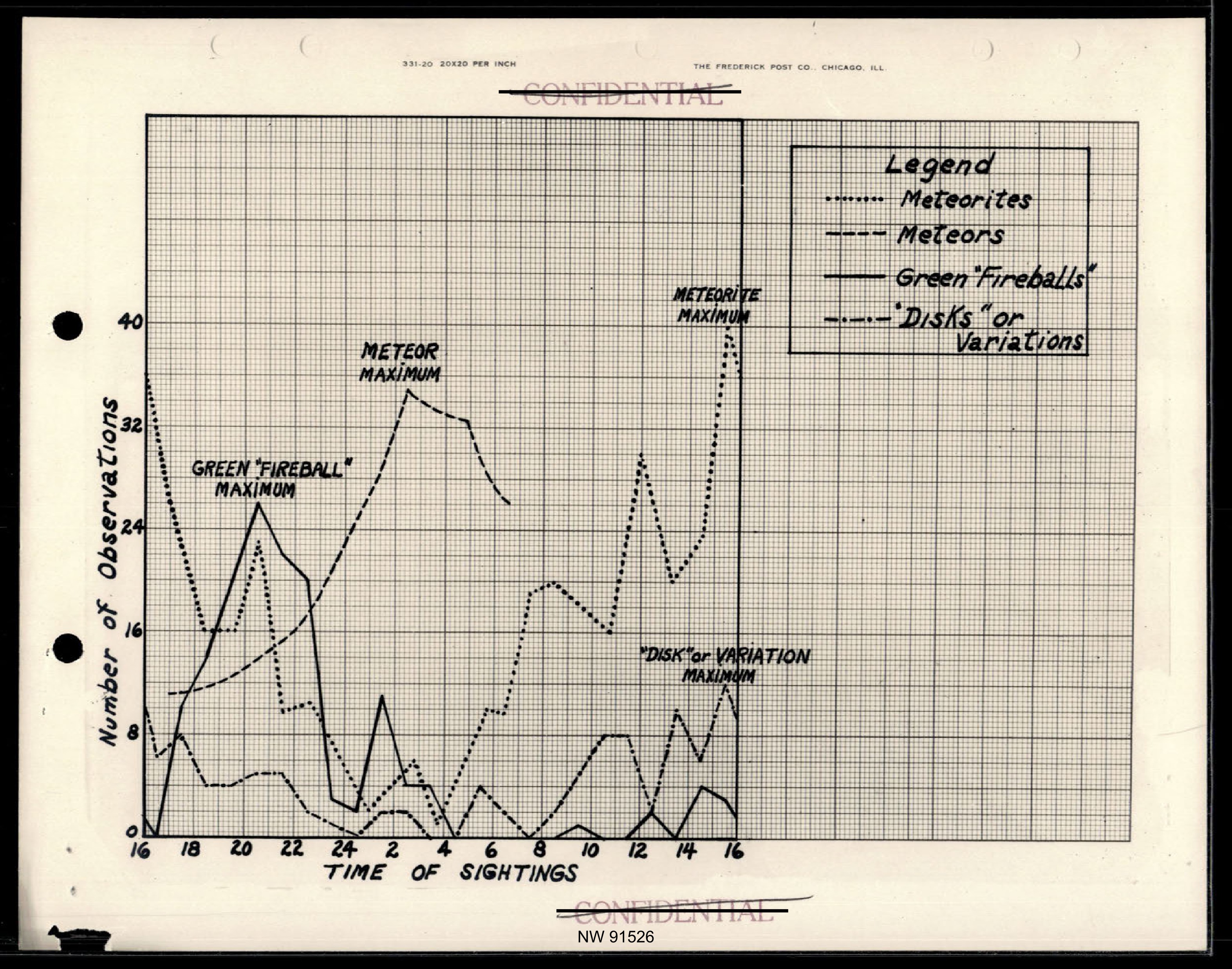
Chart of Number of Observations vs. Time of Sightings for Meteorites, Meteors, Green 'Fireballs', and 'Disks' or Variations
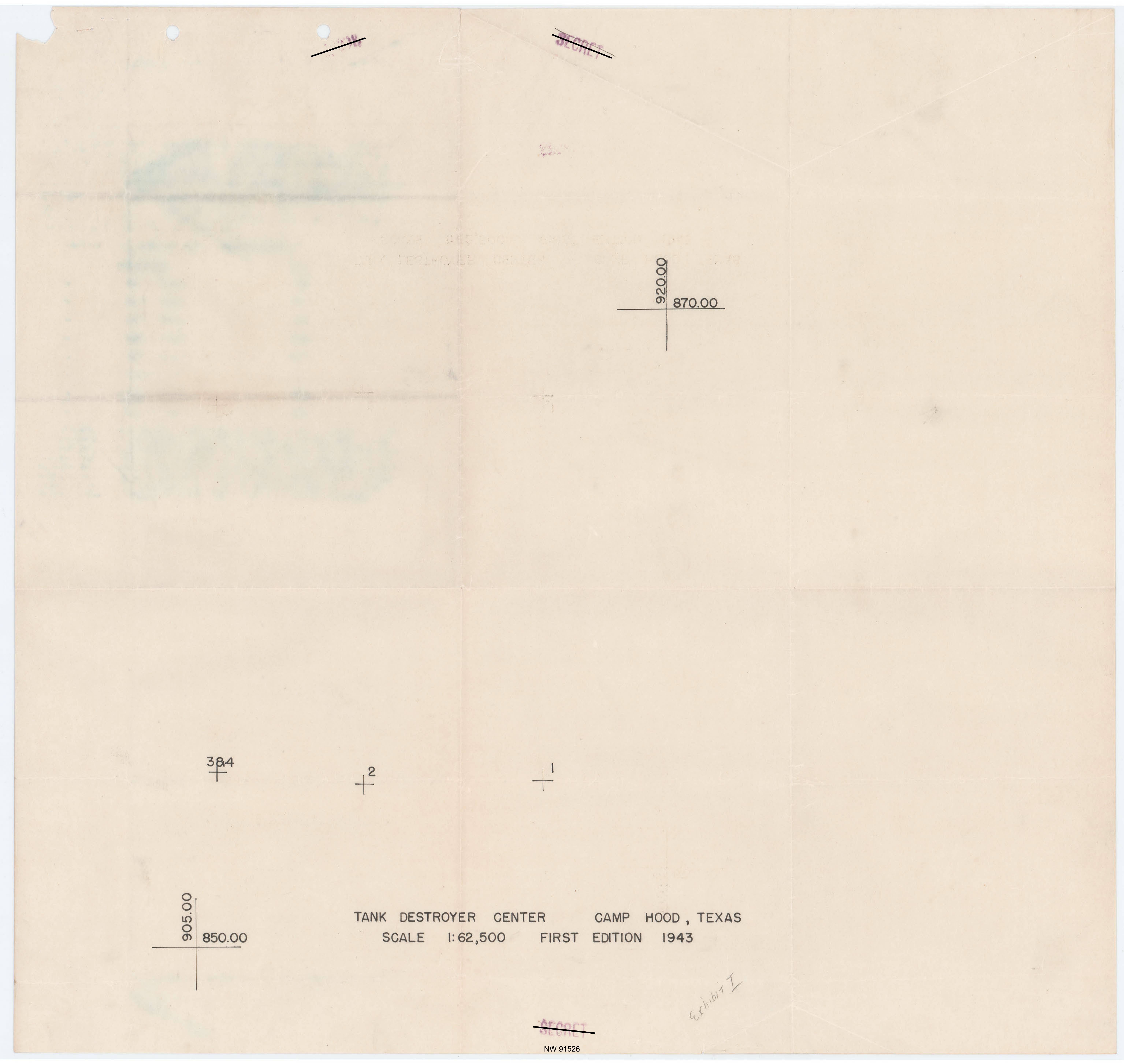
Map of Tank Destroyer Center, Camp Hood, Texas. Scale 1:62,500, First Edition 1943.
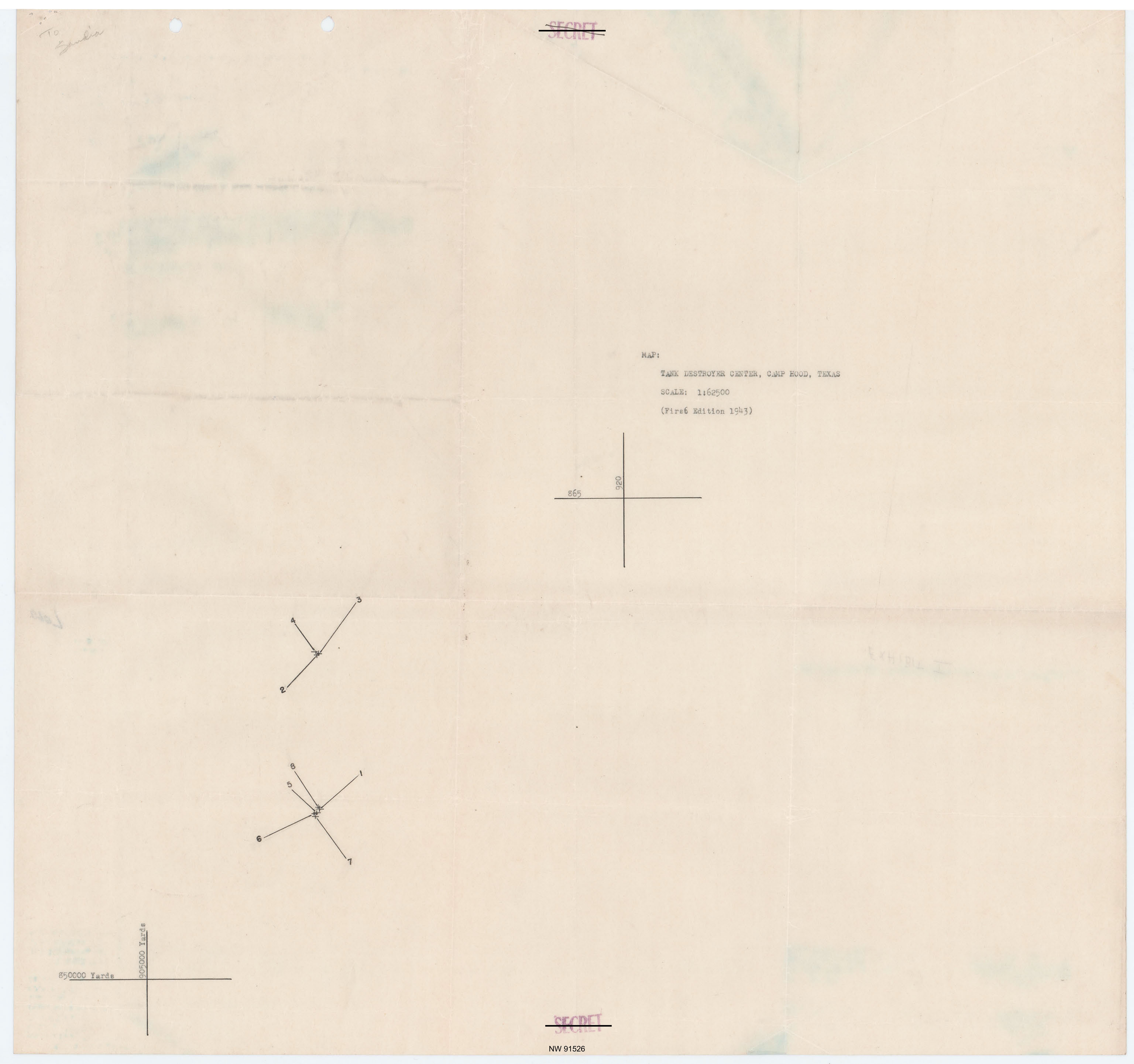
Map of Tank Destroyer Center, Camp Hood, Texas, with handwritten overlay showing points and paths.
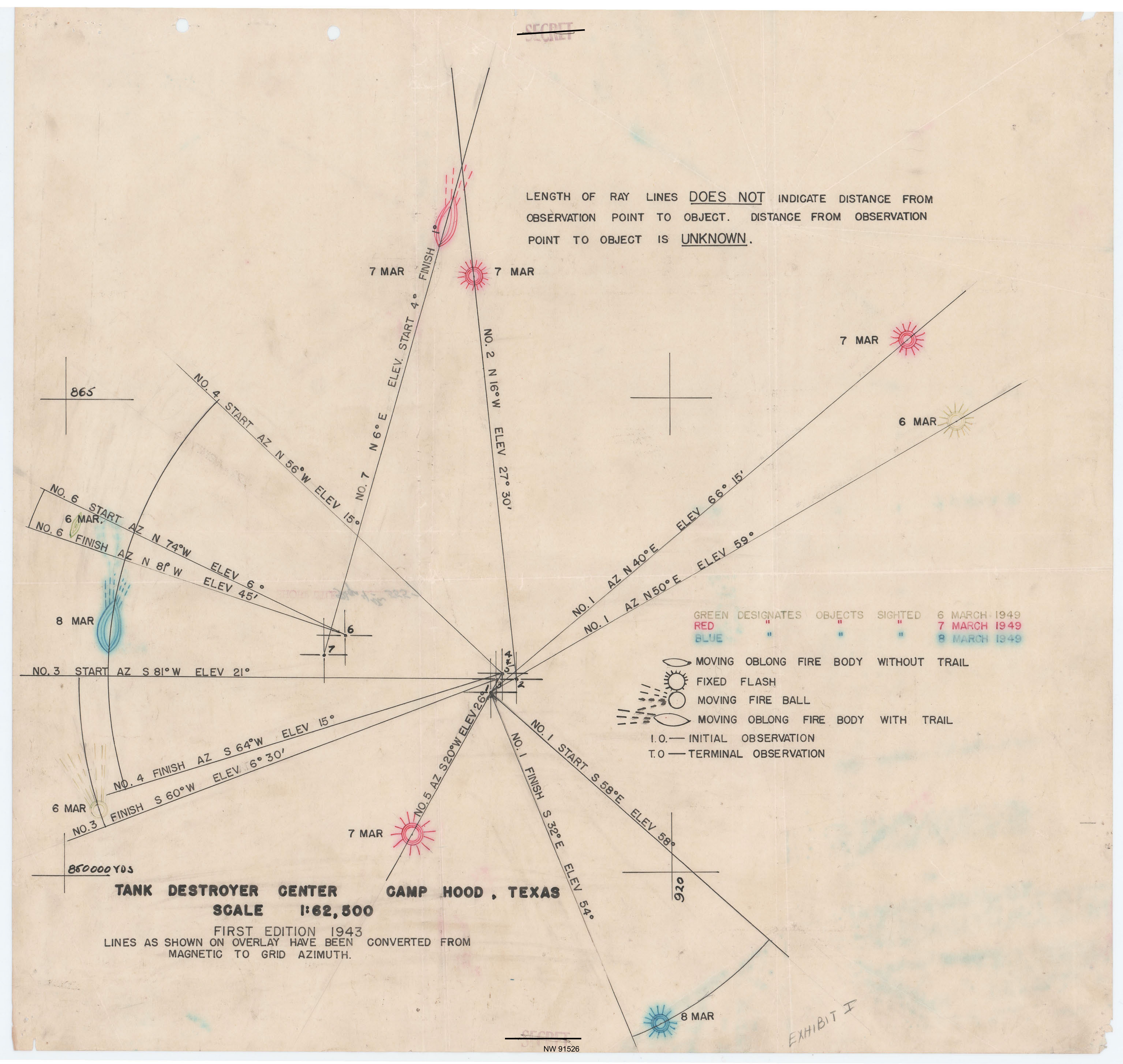
Map overlay for Camp Hood, Texas, showing sighting paths, angles, and a legend for objects sighted on March 6, 7, and 8, 1949.
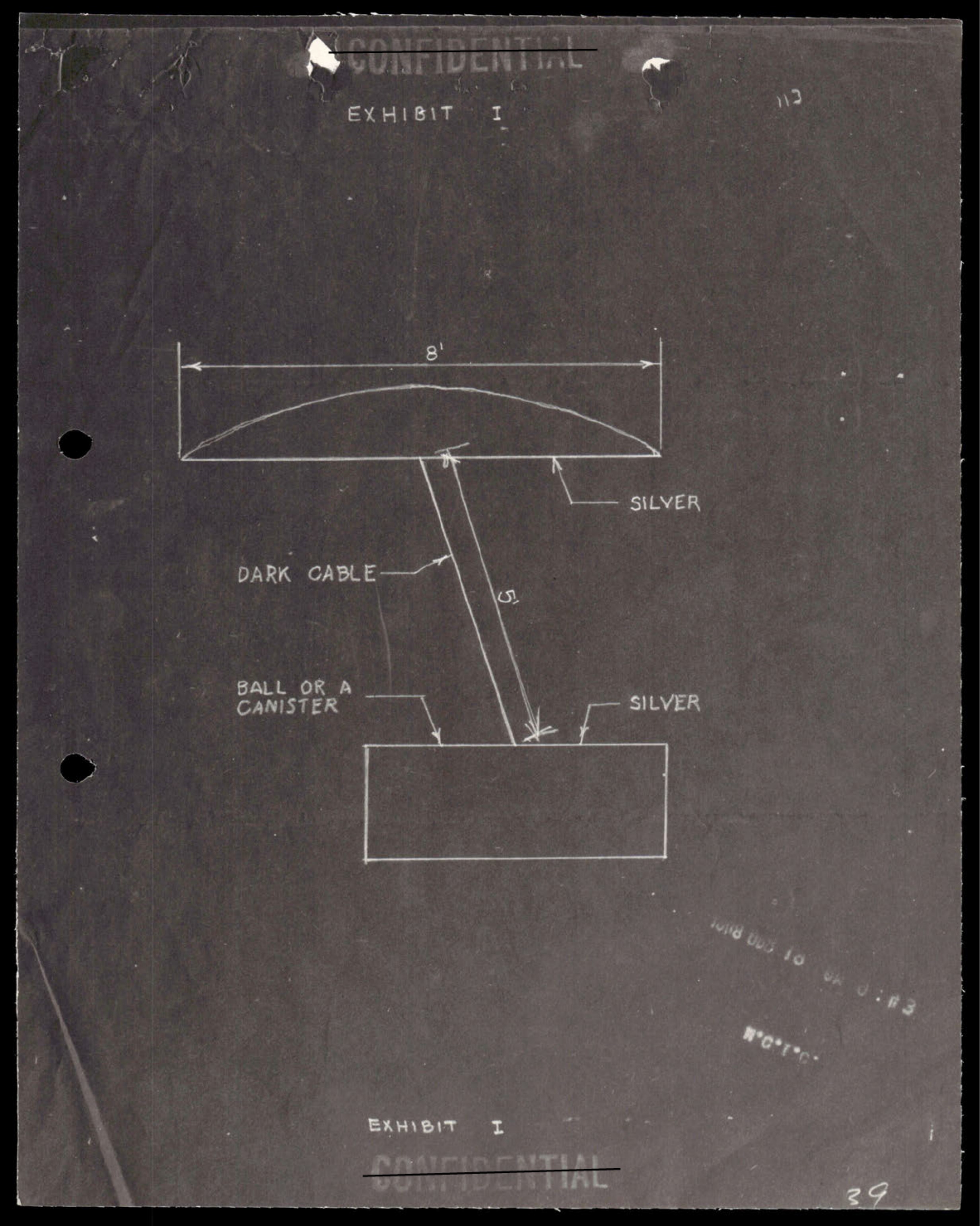
Technical diagram showing an 8-foot silver object with dark cable connecting to a ball or canister below
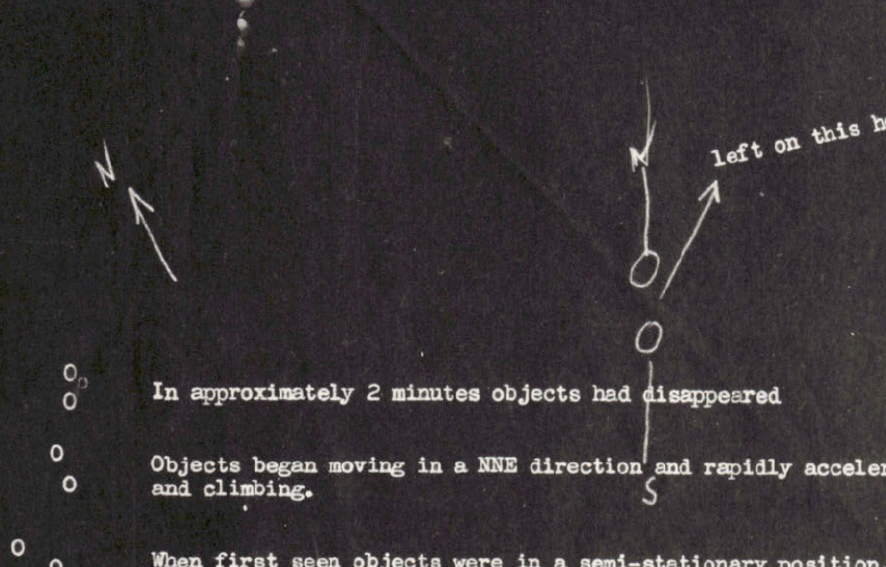
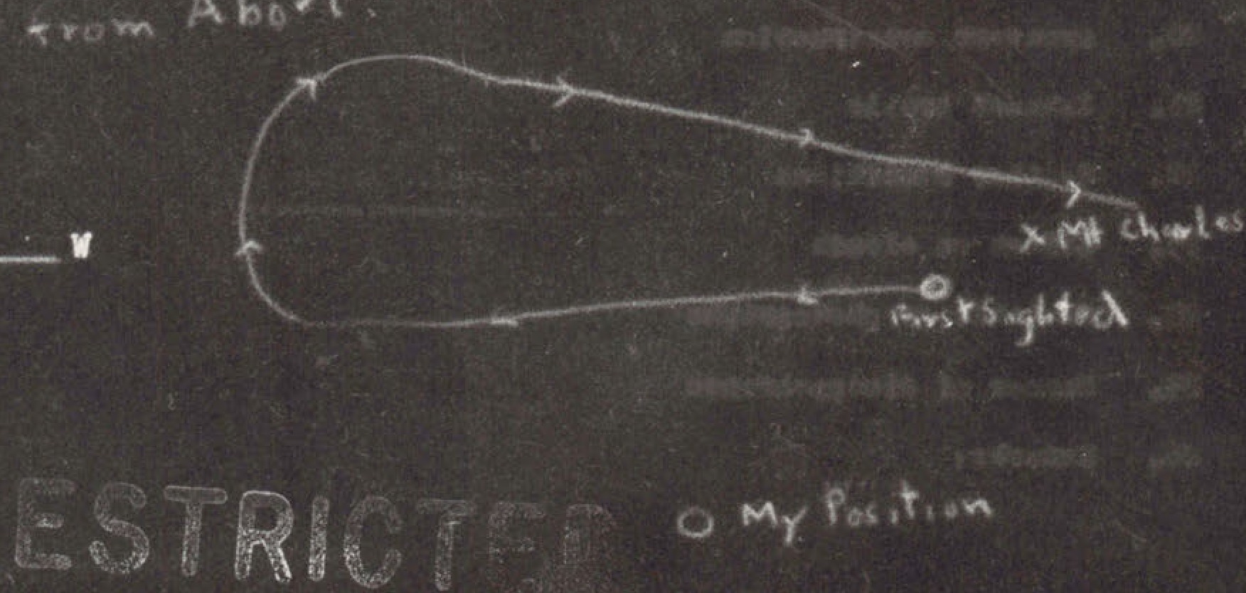
Hand-drawn diagram showing object movement with arrows and annotations
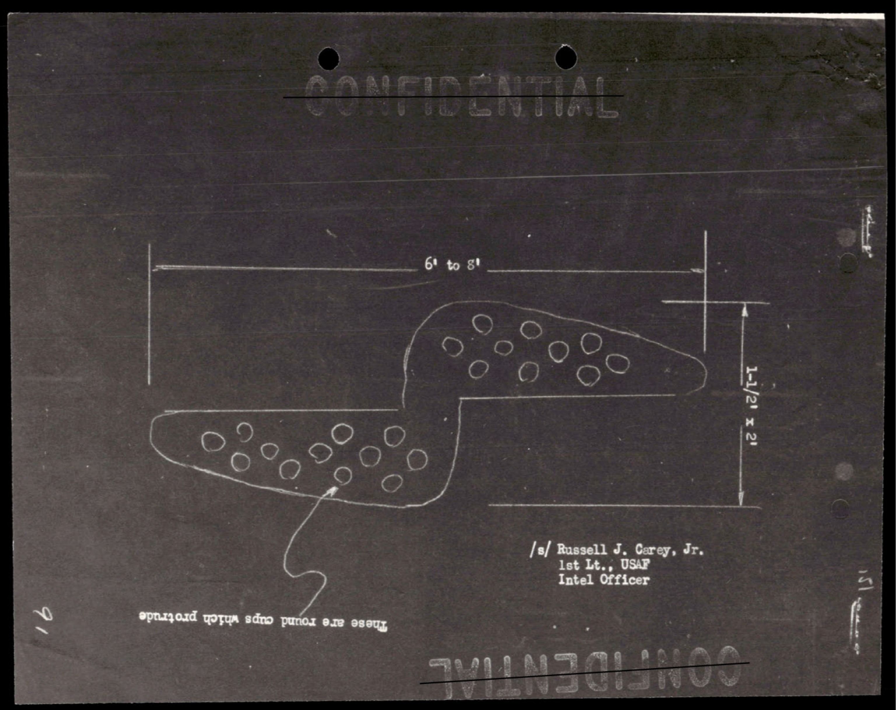
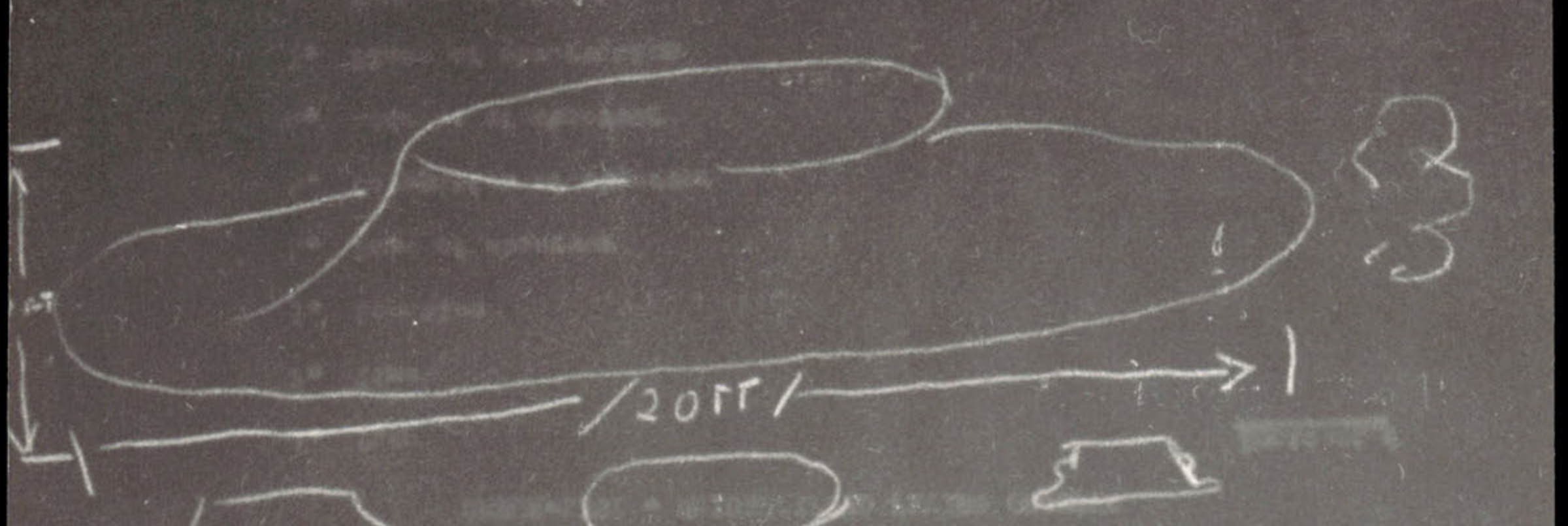
Technical diagram showing two irregular oval shapes with circular patterns inside, with dimensional measurements of 61 to 81 and 5 1/2" - 12"
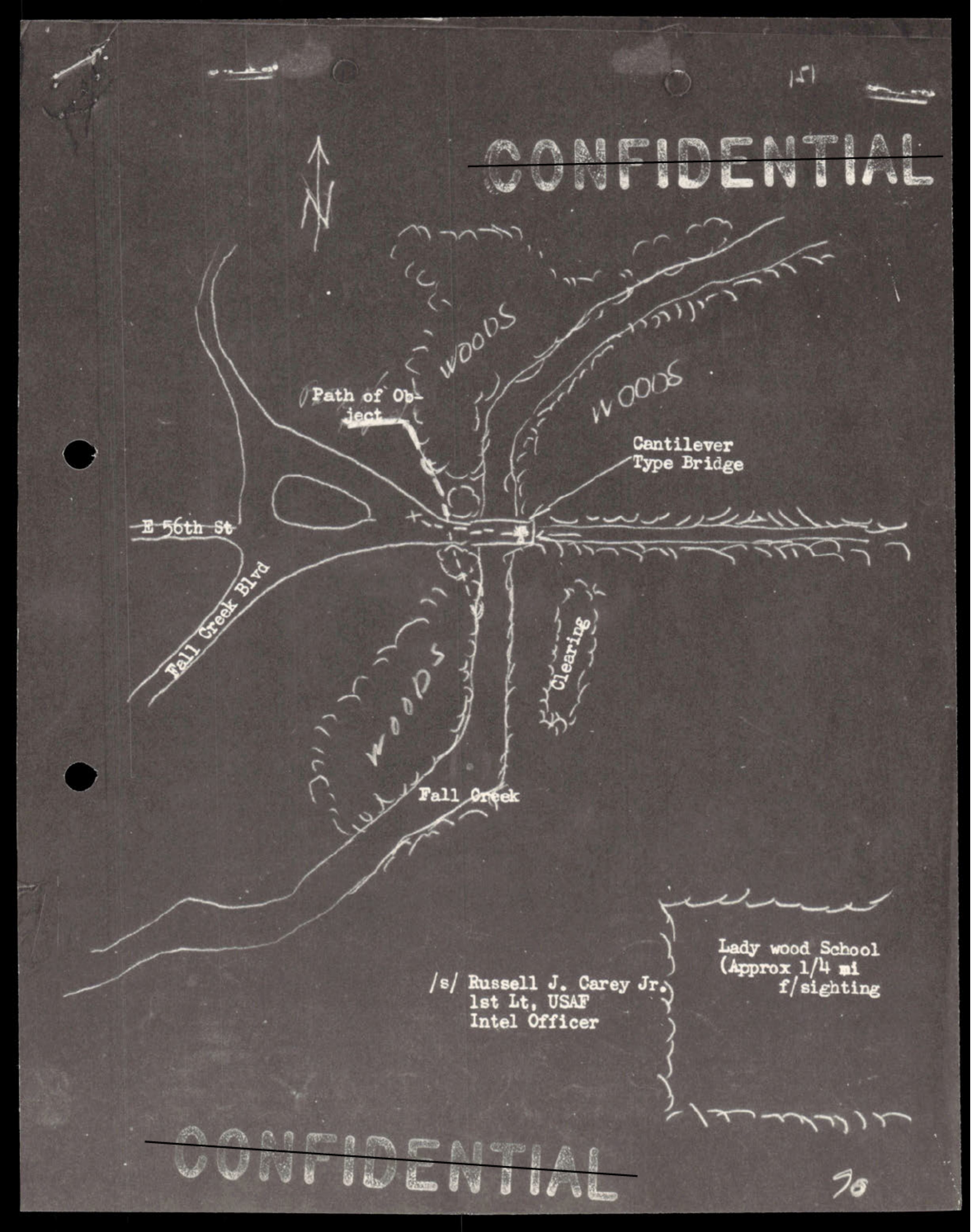
Hand-drawn map showing intersection of E 56th St and Fall Creek Blvd with woods, Cantilever Type Bridge, and Lady Wood School marked; includes north arrow and signature of Russell J. Carey Jr., 1st Lt. USAF Intel Officer, noting approx 1/4 mile to sighting location
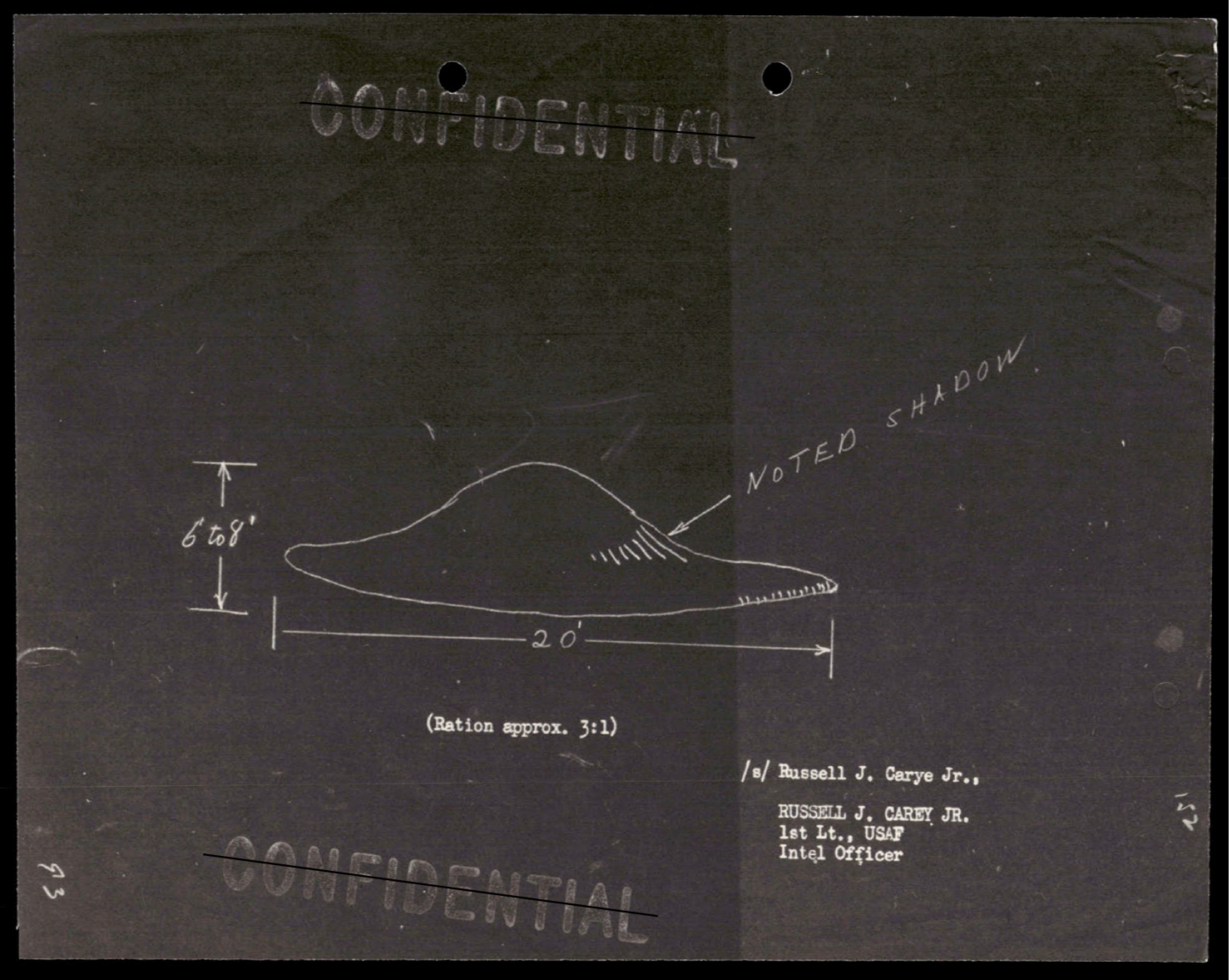
Technical sketch of disc-shaped object with dimensions: 6'8" height, 20' width, ratio approx. 3:1, with noted shadow

Four hand-drawn sketches showing object positions labeled Fourth, Third, Second, First - oval and rectangular shapes
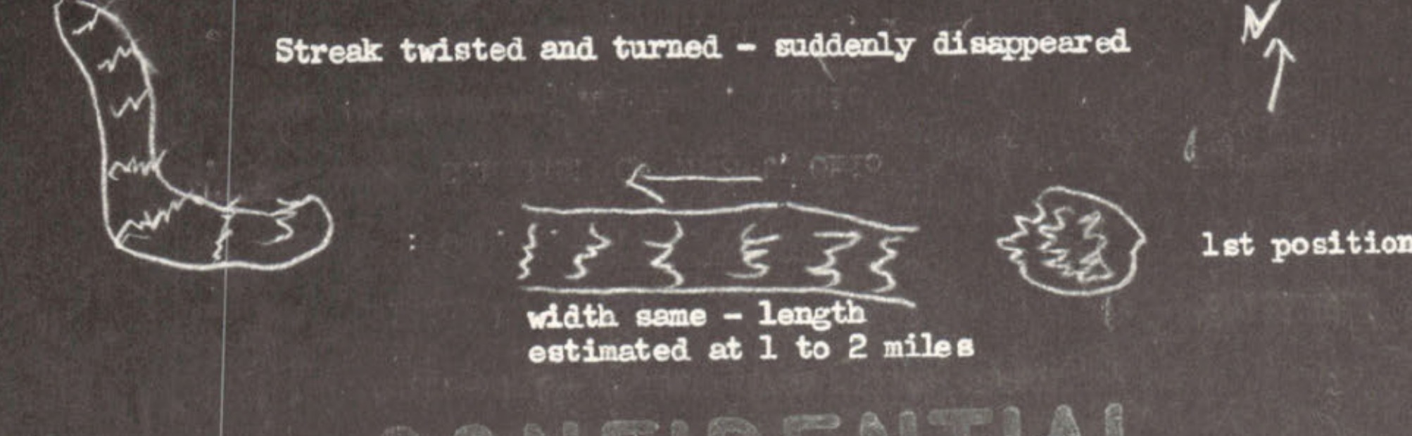
Streak twisted and turned - suddenly disappeared; width same as estimated at 1 to 2 miles; 1st position
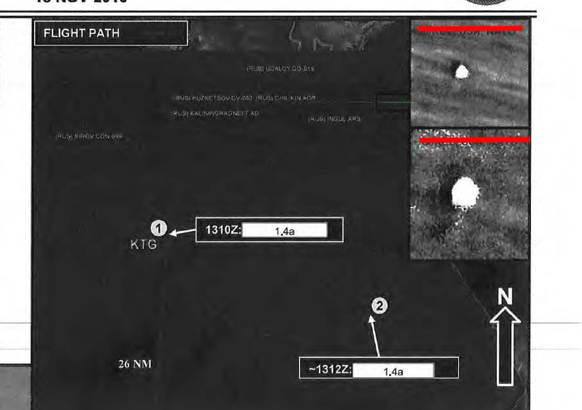
Diagram labeled 'FLIGHT PATH' showing the track of an object from KTG, with labels for Russian vessels (KIROV, UDALOY, KUZNETSOV, CHILIKIN, KALININGRADNEFT, INGUL ARS), and the US P-8A location at 1310Z.
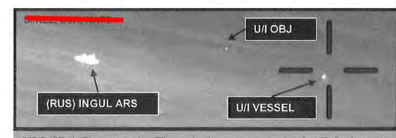
Diagram showing relative positions of '(RUS) INGUL ARS', a 'U/I VESSEL', and a 'U/I OBJ' (Unidentified Object).
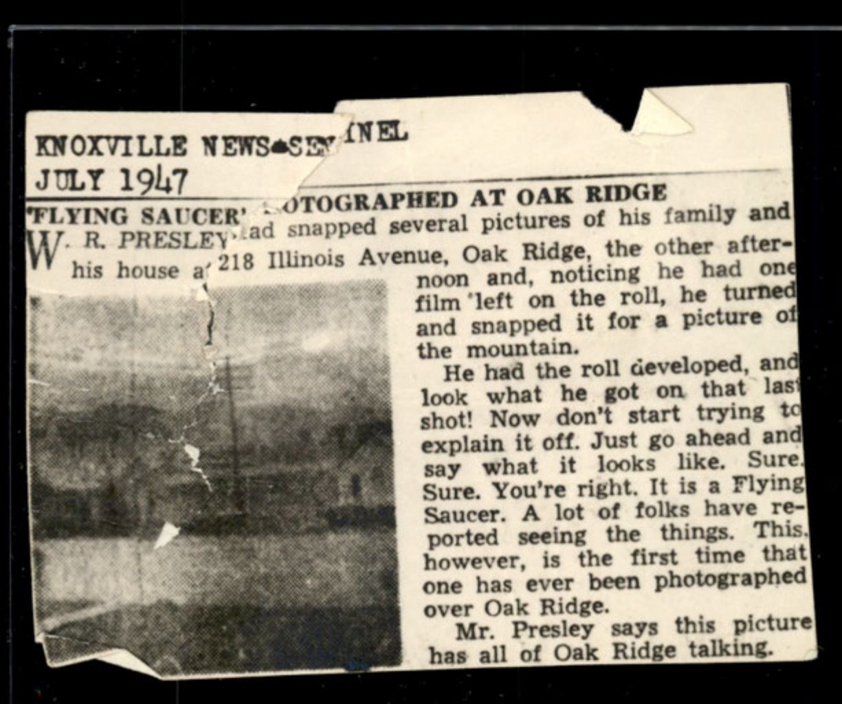
Photograph showing a dark disc-shaped object in the sky above a mountain landscape with utility pole
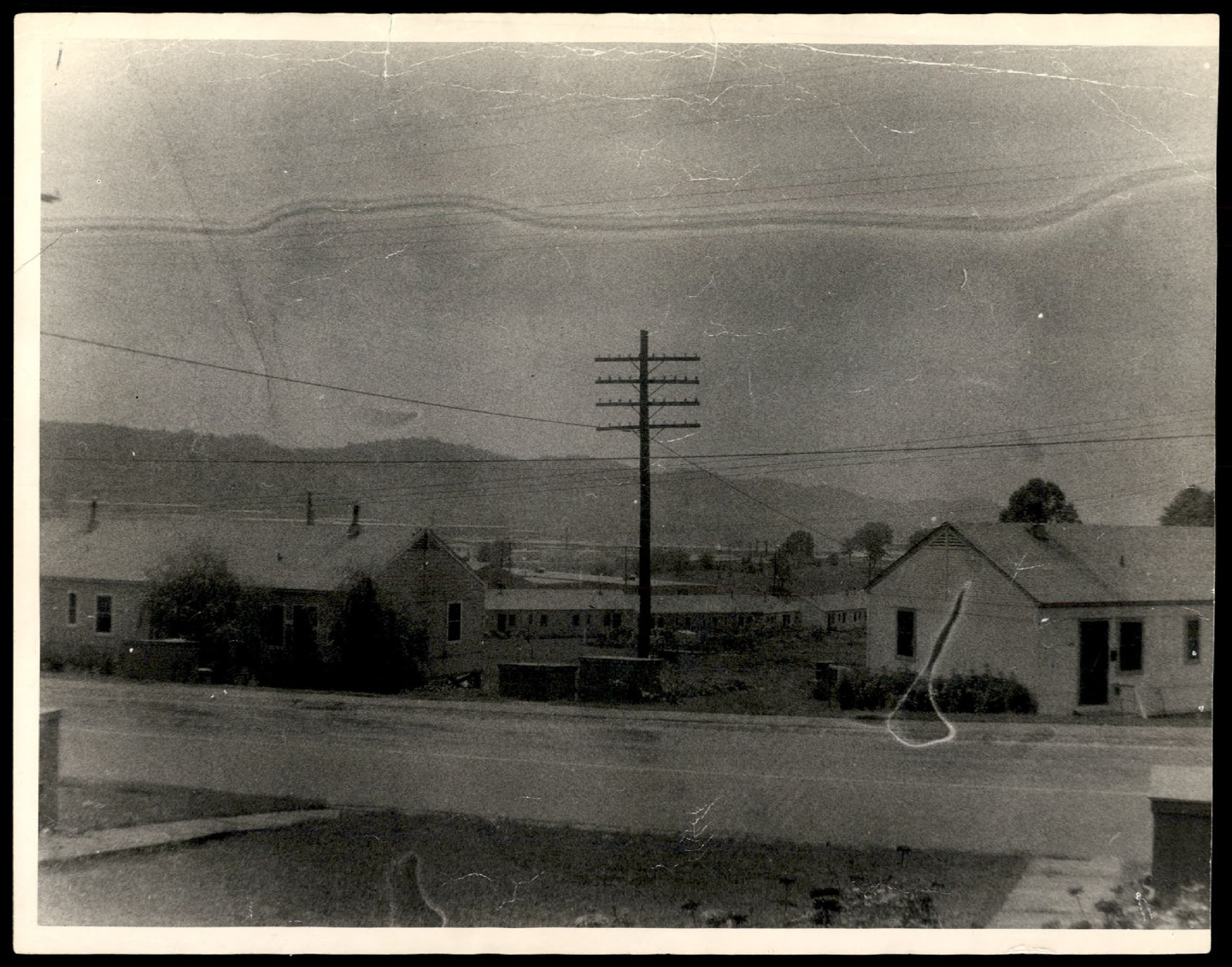
Photograph of a residential area with houses, a road, a telephone pole, and mountains in the background. This appears to be a photo of the scene without the anomalous object.
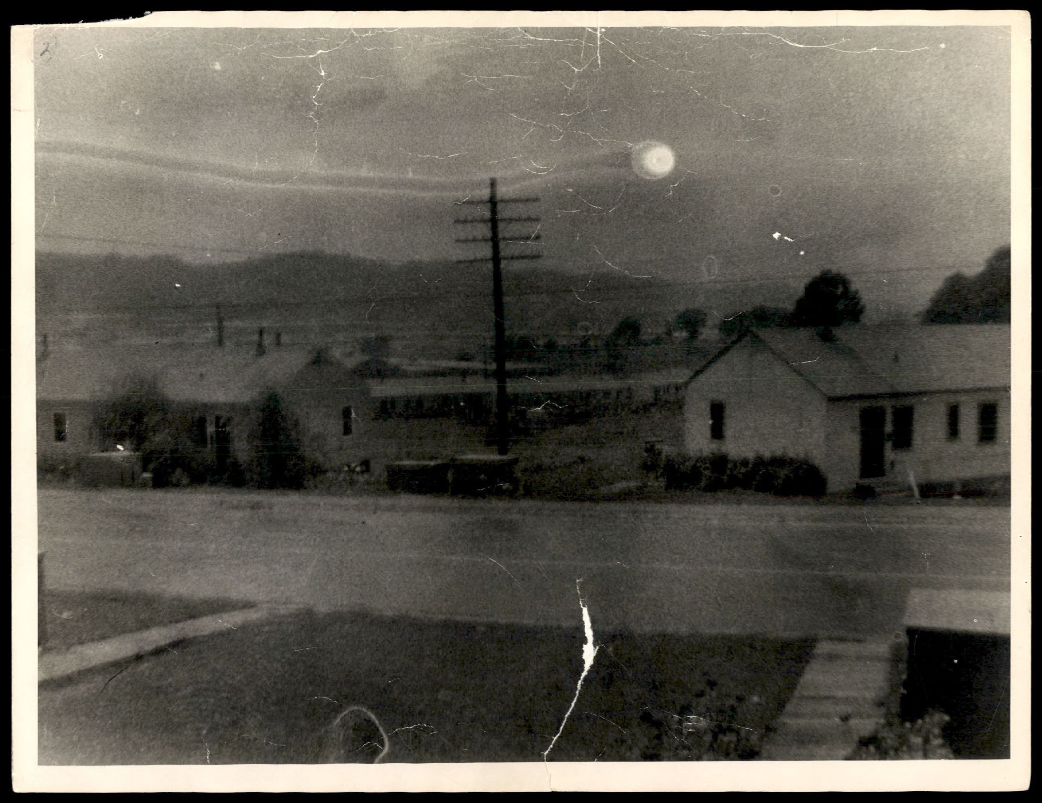
Photograph of the same scene as the previous photo, but with a bright, circular object visible in the sky. This is the 'flying saucer' photograph.
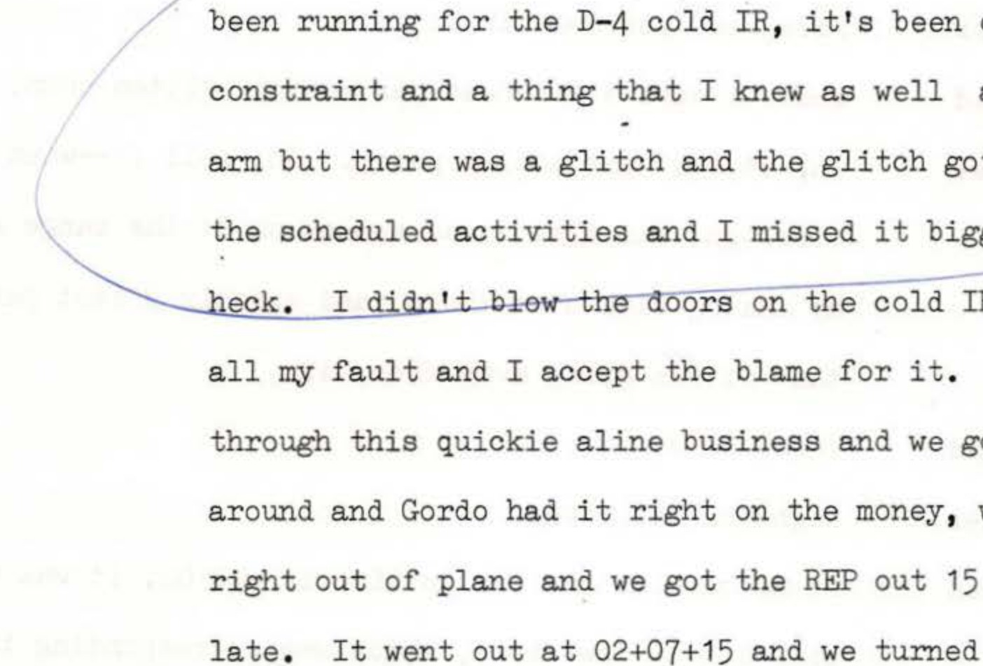
Hand-drawn curved bracket highlighting text about cold IR doors and Flight Plan
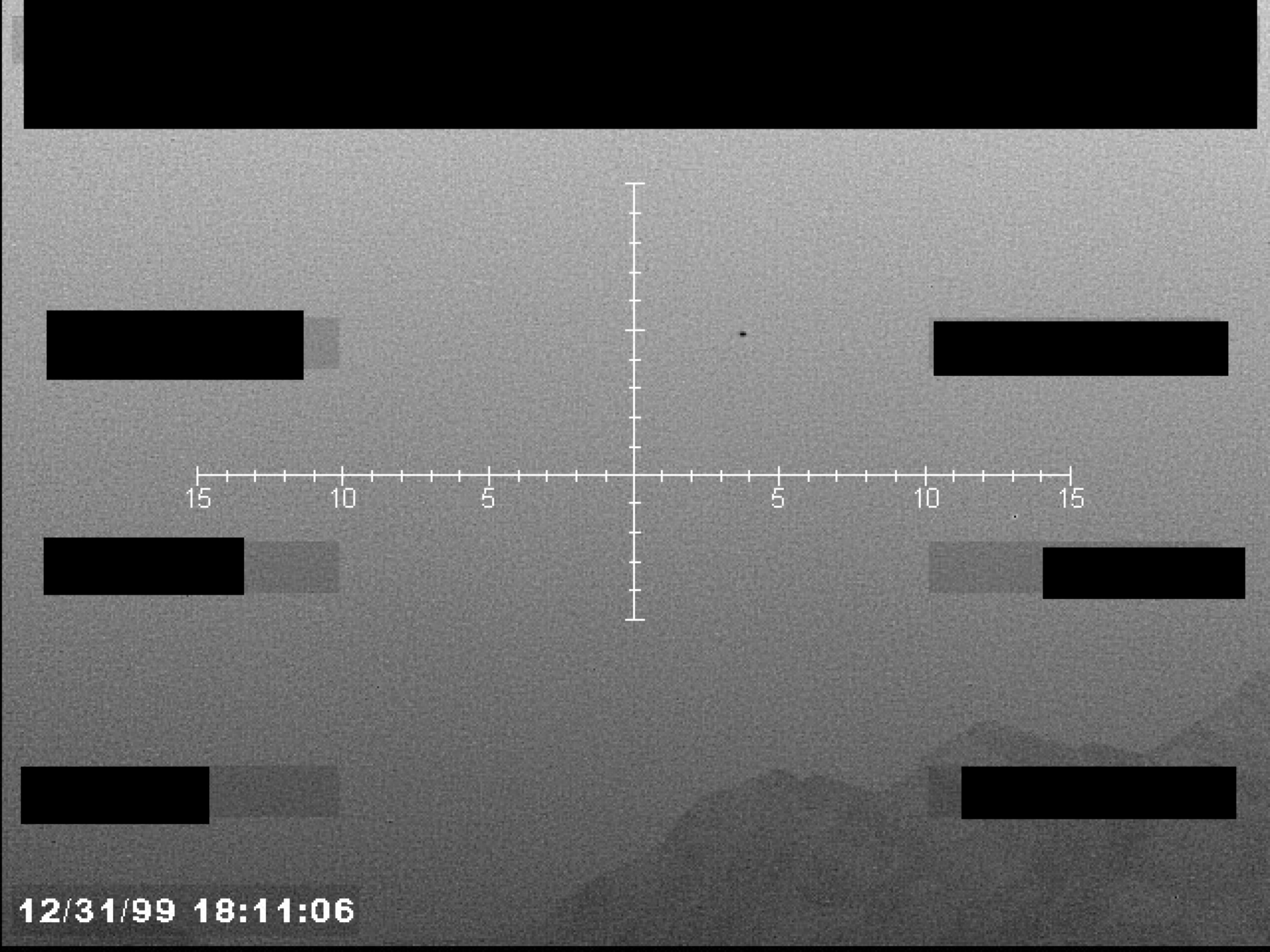
Grayscale sensor image with a central crosshair, numerical markings, and a timestamp in the lower-left corner. Several data blocks are redacted.